EP1598960A1 - Optisches Übertragungssystem - Google Patents
Optisches Übertragungssystem Download PDFInfo
- Publication number
- EP1598960A1 EP1598960A1 EP04023401A EP04023401A EP1598960A1 EP 1598960 A1 EP1598960 A1 EP 1598960A1 EP 04023401 A EP04023401 A EP 04023401A EP 04023401 A EP04023401 A EP 04023401A EP 1598960 A1 EP1598960 A1 EP 1598960A1
- Authority
- EP
- European Patent Office
- Prior art keywords
- optical
- pump light
- station
- amplification
- optical signal
- Prior art date
- Legal status (The legal status is an assumption and is not a legal conclusion. Google has not performed a legal analysis and makes no representation as to the accuracy of the status listed.)
- Granted
Links
Images


Classifications
-
- H—ELECTRICITY
- H04—ELECTRIC COMMUNICATION TECHNIQUE
- H04B—TRANSMISSION
- H04B10/00—Transmission systems employing electromagnetic waves other than radio-waves, e.g. infrared, visible or ultraviolet light, or employing corpuscular radiation, e.g. quantum communication
- H04B10/29—Repeaters
- H04B10/291—Repeaters in which processing or amplification is carried out without conversion of the main signal from optical form
- H04B10/293—Signal power control
- H04B10/2933—Signal power control considering the whole optical path
- H04B10/2937—Systems with a repeater placed only at the beginning or the end of the system, i.e. repeaterless systems, e.g. systems with only post and pre-amplification
Definitions
- the present invention relates to an optical transmission system, and more particularly, to an optical transmission system for branching optical signals to allow the optical signals to be communicated among at least three stations or more.
- a submarine optical transmission system is a system whereby stations are interconnected by optical fiber cables laid under water for optical transmission.
- an optical branching device is placed between stations to branch optical signals.
- repeaters are arranged in the middle of optical fiber cables.
- the repeaters are fed with electricity from stations to repeat and amplify optical signals.
- the optical branching device also plays the role of switching paths for feeding electricity to such repeaters.
- FIGS. 6 and 7 illustrate the configuration of a conventional submarine optical transmission system.
- the submarine optical transmission system 50 comprises terminal stations 51 and 52, a branch station 53, and an optical branching device 54.
- the terminal stations 51 and 52 and the branch station 53 are land stations while the optical branching device 54 is placed under water.
- lines interconnecting stations include an optical fiber cable for transmitting optical signals and a metallic power supply line for feeding electricity. Accordingly, the configuration of optical fiber cables and the configuration of power supply lines are separately illustrated in FIGS. 6 and 7, respectively.
- repeaters 61 to 64 are inserted in lines L1 and L2 interconnecting the terminal station 51 and the optical branching device 54 (lines interconnecting a terminal station and an optical branching device are referred to as trunk lines), and repeaters 65 to 68 are inserted in trunk lines L3 and L4 interconnecting the terminal station 52 and the optical branching device 54.
- the repeaters 61 to 68 of the trunk lines have repeater amplifiers 61a to 68a, respectively, for amplifying optical signals flowing from the terminal station 51 toward the terminal station 52, and also have repeater amplifiers 61b to 68b, respectively, for amplifying optical signals flowing from the terminal station 52 toward the terminal station 51.
- the repeaters 62, 64, 65 and 67 which are nearest to the optical branching device 54 are generally located at a distance of about 1/2 of the span length x from the optical branching device 54.
- such repeaters are arranged at locations such that the distance of the sum of the two intervals (e.g., ⁇ distance between the repeater 62 and the optical branching device 54 ⁇ + ⁇ distance between the repeater 65 and the optical branching device 54 ⁇ ) is nearly equal to the span length x.
- repeaters 71 and 72 are inserted in lines (referred to as branch lines) L5 and L6 interconnecting the branch station 53 and the optical branching device 54.
- the branch station 53 is situated, for example, on an island located in the ocean between the terminal stations 51 and 52.
- the distance between the branch station 53 and the optical branching device 54 is shorter than the transmission distance between each terminal station and the optical branching device and therefore, in some cases, no repeaters are needed.
- repeaters are inserted also in the branch lines because of the need to extend the cable length by reason of geographical features of the ocean floor etc. or to improve the quality of optical transmission (generally, where the distance Y between the branch station and the optical branching device is longer than about 1/2 of the span length X, repeaters are inserted also in the branch lines).
- the repeaters 71 and 72 of the branch lines have repeater amplifiers 71a and 72a, respectively, for amplifying optical signals transmitted from the branch station 53 to the optical branching device 54, and also have repeater amplifiers 71b and 72b, respectively, for amplifying optical signals transmitted from the optical branching device 54 to the branch station 53.
- an optical signal output from the terminal station 51 onto the trunk line L1 is amplified by the repeater amplifiers 61a and 62a and received by the optical branching device 54.
- the optical signal is output through the optical branching device 54, then amplified by the repeater amplifiers 65a and 66a of the trunk line L3, and received by the terminal station 52.
- an optical signal output from the terminal station 51 onto the trunk line L2 is amplified by the repeater amplifiers 63a and 64a and received by the optical branching device 54.
- the optical signal is diverted toward the branch station 53 by the optical branching device 54, amplified by the repeater amplifier 71b of the branch line L5, and received by the branch station 53.
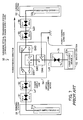
- FIG. 7 illustrates the system configuration in terms of power supply lines.
- the terminal stations 51 and 52 have power supply devices 51a and 52a, respectively, and the branch station 53 has a power supply device 53a.
- FIG. 7 shows only power supply lines Ls1, Ls3 and Ls5 associated with the trunk lines L1 and L3 and the branch line L5, respectively, and their related component parts.
- the repeater 61 includes a power supply section 61a-s for feeding electricity to the repeater amplifier 61a and a power supply section 61b-s for feeding electricity to the repeater amplifier 61b.
- the repeaters 62, 65, 66 and 71 include power supply sections 62a-s, 65a-s, 66a-s and 71a-s for feeding electricity to the repeater amplifiers 62a, 65a, 66a and 71a, respectively, and power supply sections 62b-s, 65b-s, 66b-s and 71b-s for feeding electricity to the repeater amplifiers 62b, 65b, 66b and 71b, respectively.
- the optical branching device 54 has switches SW1 to SW4 for switching power feeding paths.
- the switches SW1 to SW4 have terminals connected in such a manner that the terminals a and e, the terminals b and c, and the terminals d and f are respectively connected to each other by a fixed line.
- the terminal h of the switch SW4 is grounded.
- the switch SW1 is switched to the terminal a side, the switch SW2 is open, and the switch SW3 is switched to the terminal e side. Accordingly, the power supply lines Ls1 and Ls3 are connected and electric current flows in the direction from the power supply device 51a (+) to the power supply device 52a (-), so that electricity is fed to the repeaters 61, 62, 65 and 66.
- the switch SW4 is switched to the terminal h side.
- current flows through the power supply line Ls5 in the direction from the power supply device 53a (+) to the ground (GND), so that electricity is fed to the repeater 71. While in this state, all repeaters on the lines are capable of operation, permitting optical communication among the terminal stations 51 and 52 and the branch station 53.
- FIG. 8 illustrates a switched state of the power feeding paths in the case where a line fault has occurred. If a line fault occurs at the location shown in FIG. 8, communication among all stations is interrupted. It is therefore necessary that the switches SW1 to SW4 of the optical branching device 54 be switched so as to continue communication service within an as broad range as possible.
- the switch SW1 is switched to the terminal b side, the switch SW2 is switched to the terminal c side, and the switch SW4 is switched to the terminal g side. Also, the power supply device 53a in the branch station 53 is changed to negative power supply.
- the power supply lines Ls1 and Ls5 are connected and current flows in the direction from the power supply device 51a (+) to the power supply device 53a (-), whereby electricity is fed to the repeaters 61, 62 and 71, permitting communication to be continued between the terminal station 51 and the branch station 53.
- the repeaters 71 and 72 are inserted in the branch lines L5 and L6, respectively, and thus need to be fed with electricity from the branch station 53.
- the optical branching device 54 is required to perform switching control for the power feeding paths in case a line fault occurs, in order to continue communication service within an as broad range as possible, and thus is constantly put under high pressure. Accordingly, the optical branching device 54 needs to have a high pressure-resistant structure and requires high pressure-resistant electric relays (vacuum relays etc.), and this makes the device expensive. Also, since the branch station 53 includes the power supply device 53a, the cost of the overall system increases.
- the optical branching device 54 need not have the power switching function and the branch station 53 need not be equipped with the power supply device 53a, making it possible to construct an inexpensive system.
- the optical transmitting/receiving function of the branch station 53 is required to meet rigorous specifications.
- the optical branching device 54 may be located as near to the branch station 53 as possible to shorten the transmission distance. Because of the problem of geographical features of the ocean floor or cable route, however, it is very often difficult in practice to locate the optical branching device 54 near the branch station 53. For this reason, it has been difficult up to the present to construct economical submarine optical transmission systems.
- the pump light is introduced into a rare earth-doped fiber and the residual pump light is also used to amplify the optical signal input to the device.
- these techniques are focused only on efficient use of the pump light and no consideration is given to construction of systems requiring no repeaters in the branch lines.
- the present invention was created in view of the above circumstances, and an object thereof is to provide an optical transmission system which permits transmission distance to be prolonged without the need for repeaters, thus is economical and yet capable of high-quality optical transmission.
- an optical transmission system for branching optical signals to allow the optical signals to be communicated among at least three stations or more.
- the optical transmission system comprises a branch station for performing non-repeated optical communication with an optical branching point, the branch station including a light pumping section for causing pump light to enter an optical fiber through which a branched, receiving optical signal flows, to perform optical amplification by using the optical fiber as an amplification medium, and an optical branching device including an optical amplification section for redirecting the pump light originated from the branch station and propagated through a line to a paired line through which an optical signal transmitted from the branch station flows, to excite an amplification medium inserted in the paired line and doped with an active material for optical amplification and thereby amplify power of the optical signal transmitted from the branch station, and an optical branching section for branching the optical signal transmitted from the branch station as well as optical signals transmitted from other stations.
- FIG. 1 illustrates the principle of an optical transmission system according to the present invention.
- the optical transmission system 1 is a system for branching optical signals to allow the signals to be communicated among at least three stations or more and is applied, for example, to a submarine optical transmission system.
- the optical transmission system 1 comprises terminal stations 11 and 12, a branch station 30, and an optical branching device 40.
- the terminal station 11 is connected to the optical branching device 40 by trunk lines L1 and L2
- the terminal station 12 is connected to the optical branching device 40 by trunk lines L3 and L4
- the branch station 30 is connected to the optical branching device 40 by branch lines L5 and L6.
- Repeaters 21 and 22 are inserted in the trunk line L1, and repeaters 23 and 24 are inserted in the trunk line L2.
- Repeaters 25 and 26 are inserted in the trunk line L3, and repeaters 27 and 28 are inserted in the trunk line L4.
- the branch lines L5 and L6 have no repeaters arranged therein and thus, non-repeated transmission is performed.
- the branch station 30 includes light pumping sections 31-1 and 31-2 and carries out non-repeated optical communication with the optical branching device 40.
- the light pumping sections 31-1 and 31-2 each cause pump light to enter an optical fiber through which an optical signal branched by an optical branching section 42 (a receiving optical signal to be received by the branch station 30) flows, to perform optical amplification by using the optical fiber as an amplification medium.
- the optical branching device 40 is constituted by optical amplification sections 41-1 and 41-2 and the optical branching section 42.
- the optical amplification sections 41-1 and 41-2 each redirect the pump light originated from the branch station 30 and propagated through the line to the paired line through which the optical signal transmitted from the branch station 30 flows, to excite an amplification medium 41c inserted in the paired line and doped with an active material for optical amplification and thereby amplify the power of the optical signal transmitted from the branch station 30.
- the optical branching section 42 branches the optical signal transmitted from the branch station 30 (e.g., the amplified optical signal transmitted from the branch station 30 is directed to the terminal station 11) as well as optical signals transmitted from the other stations (e.g., the optical signal from the terminal station 11 is directed to the branch station 30 or to the terminal station 12).
- the optical branching section 42 may switch optical signal paths for respective optical fibers (as in the system described above with reference to FIG. 6).
- the optical branching section 42 may perform OADM (Optical Add Drop Multiplex) control to drop and insert optical signals of respective wavelengths. Namely, with respect to wavelength-multiplexed signals communicated between the terminal stations 11 and 12, signals of specified wavelengths are dropped to the branch station 30 or the signals from the branch station 30 are added.
- OADM Optical Add Drop Multiplex
- FIG. 2 illustrates the configurations of the branch station 30 and the optical branching device 40.
- FIG. 2 shows only those component parts which are related with the branch connection between the terminal station 11 and the branch station 30 through the optical amplification section 41-1 and the optical branching section 42.
- the terminal station 11 and the optical branching device 40 are interconnected by trunk lines L2a and L2b, and the repeaters 23 and 24 are inserted in the trunk lines.
- the repeater 23 includes repeater amplifiers 23a and 23b, and the repeater 24 includes repeater amplifiers 24a and 24b.
- the branch station 30 and the optical branching device 40 are interconnected by branch lines L5a and L5b.
- the repeating interval (usually called span length) between the repeaters 23 and 24 of the trunk lines L2a and L2b is 60 km
- the interval between the repeater 24 and the optical branching device 40 is 30 km
- the interval between the branch station 30 and the optical branching device 40 interconnected by the branch lines L5a and L5b is equal to the ordinary span length and therefore, 60 km (in the conventional system, repeaters need to be inserted in the branch lines, but the present invention does not require such repeaters) .
- the branch station 30 is constituted by the light pumping section 31-1, an optical receiving section 32, and an optical transmitting section 33.
- the light pumping section 31-1 includes a pump light source 31a and a multiplexer 31b.
- the optical branching device 40 is constituted by the optical amplification section 41-1 and the optical branching section 42.
- the optical amplification section 41-1 includes a demultiplexer 41a, a multiplexer 41b, and the amplification medium 41c.
- the multiplexer 31b for multiplexing an optical signal D1 with pump light R is connected to the line immediately short of the receiving end of the branch station 30, and the pump light source 31a is connected to the multiplexer such that the pump light R is propagated in a direction opposite to the direction of the receiving optical signal D1 (to carry out backward pumping).
- the pump light R travels through the branch line L5a, so that the optical signal D1 undergoes Raman amplification, due to the pump light R, within the optical fiber constituting the transmission path of the branch line L5a.
- the optical signal D1 is received by the optical receiving section 32 through the multiplexer 31b.
- Raman amplification makes use of the physical phenomenon that light with wavelengths different from those of incident light is scattered due to oscillations within a material, and is caused to take place by introducing intense pump light into an optical fiber transmission path to achieve optical amplification by using the optical fiber transmission path itself as an amplification medium.
- the peak of the gain induced by Raman scattering appears at a frequency position shifted on the longer wavelength side by about 100 nm. Namely, an optical signal with a wavelength longer than that of the incident pump light by about 100 nm is pumped.
- an optical signal with a wavelength of 1.55 ⁇ m for example, pump light with a wavelength in the vicinity of the range from 1.45 to 1.48 pm, which is shorter in wavelength than the optical signal by about 100 nm, is introduced into the optical fiber transmission path.
- the demultiplexer 41a in the optical amplification section 41-1 separates the pump light R transmitted from the branch station 30 and redirects the separated light to a line L0 interconnecting the demultiplexer 41a and the multiplexer 41b.
- the multiplexer 41b multiplexes the separated pump light R (pump light remaining after Raman amplification) with an optical signal D2 transmitted from the paired line (branch line L5b). At this time, the pump light R and the optical signal D2 are multiplexed such that their propagation directions are opposite to each other.
- a fiber doped with a rare-earth element e.g., EDF (Erbium-Doped Fiber) doped with erbium (Er 3+ )
- EDF 41c Erbium-Doped Fiber
- the level of the optical signal increases due to the stimulated emission then induced.
- the redirected pump light R1 propagated through the line L0 is used as the pump light for the EDF 41c to amplify the power of the optical signal D2 transmitted from the branch station 30.
- the optical signal D1 flowing through the branch line L5a is subjected to Raman amplification by the pump light R while the optical signal D2 flowing through the branch line L5b is amplified by the EDF 41c into which the redirected pump light R1 is introduced, making it unnecessary to insert repeaters in the branch lines interconnecting the optical branching device 40 and the branch station 30.
- the redirected pump light (residual pump light) is introduced into the EDF.
- the pump light (pump light for the EDF) originated from the pump light source is introduced into the EDF, and the pump light output from one end of the EDF is reflected by a mirror to be again introduced into the EDF.
- the techniques do no use Raman pump light which has been propagated through a line, but the pump light for the EDF is merely reflected inside the device and reused just to amplify the optical signal flowing through a single line.
- the Raman pump light propagated through one line is redirected to the other paired line so that the redirected pump light may be introduced into the EDF inserted in the paired line.
- This arrangement permits amplification control to be performed such that the optical amplifications of up- and down-lines are interrelated with each other. Since Raman amplification is performed with respect to one of the up- and down-lines while optical amplification by means of the EDF is performed with respect to the other line, optical signals on the two lines can be amplified with high efficiency, and as a consequence, no repeaters need to be arranged in the up- and down-lines.
- FIG. 3 is a diagram showing set values given as initial conditions.
- the optical fiber transmission path loss, ordinary span length, repeater input/output power and branch station input/output power are set to the respective values indicated in FIG. 3.
- the power of the optical signal D1 input to the branch station 30 (the branch station input power at a location P1 in FIG. 2) will be considered.
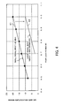
- FIG. 4 shows the relation between pump light power (W) and Raman amplification gain (dB), wherein the horizontal axis indicates pump light power (W) and the vertical axis indicates Raman amplification gain (dB).
- Curve K1 shows the relation between the pump light power and the Raman amplification gain observed when backward Raman pumping is performed (the pump light is introduced in a direction opposite to that of signal light) with respect to an optical signal with small power of about -20 dBm.
- the power of the optical signal is significantly small (-20 dBm or below)
- a gain of 20 dB or more can be obtained using 1 W pump light.
- the power of the optical signal is about -5 dBm, as mentioned in (a) above. Since the optical signal D1 with relatively large power is input, the gain remains small even for the same pump light power. Assuming that the gain is 10 dB or less, the relation between the pump light power and the Raman amplification gain observed in the case where backward Raman pumping is performed with respect to an optical signal with large power of about -5 dBm can be plotted as curve K2 (estimated curve). The curve K2 indicates that when the pump light power is 1 W, the optical signal acquires a gain of 10 dB.
- the "gain that the optical signal D1 acquires when the pump light R is introduced" is 10 dB if the output of the pump light source 31a is 1 W.
- the input power of the repeater amplifier 24b (power at a location P2 in FIG. 2) will be now considered. It is assumed here that the pump light source 31a with a pump power of 1 W is used.
- 1 W of pump light power is converted into decibels as equivalent to 30 dBm.
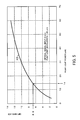
- FIG. 5 shows the relation between pump light power (mW) and EDF gain (dB), wherein the horizontal axis indicates pump light power (mW) and the vertical axis indicates EDF gain (dB).
- Curve K3 indicates the gain of the EDF relative to the pump light power observed in the case where the optical signal input was 0 dBm and the pump light wavelength was in the 1.48 ⁇ m band.
- a value on the vertical axis corresponding to 14 mW on the horizontal axis is approximately 6.9 dB. Namely, where a 1 W pump light source is used as the pump light source 31a, the gain of the EDF 41c acquired by the redirected pump light R1 which has propagated through the line for 60 km is found to be 6.9 dB.
- the input power of the repeater amplifier 24b is given by (transmit output power of the optical signal D2 from the branch station 30) - (length of the optical fiber transmission path from the branch station 30 to the repeater 24) ⁇ (fiber loss caused during optical signal transmission) + (gain of the EDF 41c).
- the gain of the EDF 41c is assumed to be 6.0 dB (even if 6.0 smaller than 6.9 is considered in anticipation of a more rigorous condition)
- +13 dBm - (60 km + 30 km) ⁇ 0.21 dB/km + 6.0 dB 0.1 dBm.
- the derived value is equal to the repeater input power (+0.1 dBm) shown in FIG. 3 as the initial condition and fulfills the repeater amplifier input condition without the use of repeater amplification, proving that the optical signal can be transmitted through the branch line L5b without the need for a repeater.
- the high-output pump light source 31a is arranged at the branch station 30 to amplify the receiving optical signal by means of Raman amplification.
- the EDF 41c is inserted in the transmit line in the optical branching device 40 through which the optical signal transmitted from the branch station 30 flows, and the pump light is redirected in the device to be introduced into the EDF 41c, so that the power of the optical signal transmitted from the branch station 30 is amplified.
- the power level of the optical signal input to the repeater amplifier 24b can be maintained at an adequate level without using repeaters inserted in the branch lines L5 while at the same time avoiding lowering of the power level of the optical signal input to the branch station 30 and without the need to increase the power of the optical signal transmitted from the branch station 30.
- the pump light is used in common to amplify the optical signal input to the branch station 30 by means of Raman amplification and to amplify the power of the optical signal transmitted from the branch station 30 by means of the EDF arranged in the optical branching device 40, and the pump light source 31a is arranged in the branch station 30. This eliminates the need to feed electricity to the branch lines L5, making it possible to construct economical systems.
- the pump light originated from the branch station and propagated through a line is redirected to the paired line through which the optical signal transmitted from the branch station flows, to excite the amplification medium inserted in the paired line and doped with an active material for optical amplification and thereby amplify the power of the optical signal transmitted from the branch station.
Applications Claiming Priority (2)
| Application Number | Priority Date | Filing Date | Title |
|---|---|---|---|
| JP2004150061A JP4458928B2 (ja) | 2004-05-20 | 2004-05-20 | 光伝送システム |
| JP2004150061 | 2004-05-20 |
Publications (2)
| Publication Number | Publication Date |
|---|---|
| EP1598960A1 true EP1598960A1 (de) | 2005-11-23 |
| EP1598960B1 EP1598960B1 (de) | 2007-12-12 |
Family
ID=34926806
Family Applications (1)
| Application Number | Title | Priority Date | Filing Date |
|---|---|---|---|
| EP04023401A Expired - Fee Related EP1598960B1 (de) | 2004-05-20 | 2004-10-01 | Optisches Übertragungssystem |
Country Status (3)
| Country | Link |
|---|---|
| US (1) | US7146071B2 (de) |
| EP (1) | EP1598960B1 (de) |
| JP (1) | JP4458928B2 (de) |
Cited By (2)
| Publication number | Priority date | Publication date | Assignee | Title |
|---|---|---|---|---|
| EP2753011A1 (de) * | 2013-01-02 | 2014-07-09 | Alcatel Lucent | Vorrichtung und Verfahren für ein OADM-Unterwassersystem |
| US20210194597A1 (en) | 2017-10-30 | 2021-06-24 | Nec Corporation | Submarine optical communication system and submarine branching apparatus |
Families Citing this family (7)
| Publication number | Priority date | Publication date | Assignee | Title |
|---|---|---|---|---|
| US7574140B2 (en) * | 2004-12-22 | 2009-08-11 | Tyco Telecommunications (Us) Inc. | Optical transmission system including repeatered and unrepeatered segments |
| JP2008148146A (ja) * | 2006-12-12 | 2008-06-26 | Nippon Telegr & Teleph Corp <Ntt> | 光伝送システム |
| US20090285584A1 (en) * | 2008-05-15 | 2009-11-19 | Xtera Communication Inc. | Unrepeatered optical segment for use with repeatered series of optical segments |
| JP2011077808A (ja) * | 2009-09-30 | 2011-04-14 | Fujitsu Ltd | 光伝送システム |
| CN103975534B (zh) * | 2011-12-22 | 2016-05-11 | 日本电气株式会社 | 分支单元和电力线监视方法 |
| US11223427B2 (en) * | 2017-03-17 | 2022-01-11 | Nec Corporation | Optical submarine cable system and optical submarine relay apparatus |
| US11153669B1 (en) * | 2019-02-22 | 2021-10-19 | Level 3 Communications, Llc | Dynamic optical switching in a telecommunications network |
Citations (1)
| Publication number | Priority date | Publication date | Assignee | Title |
|---|---|---|---|---|
| US6507431B1 (en) * | 1997-03-13 | 2003-01-14 | Fujitsu Limited | Remotely pumping type multi-wavelength light transmission system |
Family Cites Families (10)
| Publication number | Priority date | Publication date | Assignee | Title |
|---|---|---|---|---|
| US5532864A (en) * | 1995-06-01 | 1996-07-02 | Ciena Corporation | Optical monitoring channel for wavelength division multiplexed optical communication system |
| JP3036458B2 (ja) * | 1997-02-28 | 2000-04-24 | 日本電気株式会社 | 光分岐装置および光伝送方法 |
| JP3522509B2 (ja) * | 1997-10-17 | 2004-04-26 | 富士通株式会社 | 光伝送装置及び光通信システム |
| JP3605629B2 (ja) * | 1998-12-15 | 2004-12-22 | 富士通株式会社 | 光源の冗長切替方法及び該方法による波長多重伝送装置 |
| JP3787474B2 (ja) * | 1998-12-24 | 2006-06-21 | キヤノン株式会社 | 回折光学素子における2つの設計波長の設定方法 |
| US6678087B1 (en) | 1999-08-06 | 2004-01-13 | Nippon Telegraph And Telephone Corporation | Optical amplifier and optical fiber communication system using the amplifier |
| DE69941306D1 (de) * | 1999-10-29 | 2009-10-01 | Fujitsu Ltd | Optische übertragungsvorrichtung und optische zwischenverstärkungsvorrichtung |
| US6388803B1 (en) * | 2000-03-02 | 2002-05-14 | Agere Systems Guardian Corp. | Article comprising a broad band optical amplifier |
| JP4549591B2 (ja) * | 2001-09-28 | 2010-09-22 | 富士通株式会社 | 装置 |
| US6687087B2 (en) * | 2001-10-11 | 2004-02-03 | International Business Machines Corporation | System and method for visually indicating usage of magnetic tape cartridges |
-
2004
- 2004-05-20 JP JP2004150061A patent/JP4458928B2/ja not_active Expired - Fee Related
- 2004-09-14 US US10/939,410 patent/US7146071B2/en active Active
- 2004-10-01 EP EP04023401A patent/EP1598960B1/de not_active Expired - Fee Related
Patent Citations (1)
| Publication number | Priority date | Publication date | Assignee | Title |
|---|---|---|---|---|
| US6507431B1 (en) * | 1997-03-13 | 2003-01-14 | Fujitsu Limited | Remotely pumping type multi-wavelength light transmission system |
Non-Patent Citations (1)
| Title |
|---|
| TANAKA K ET AL: "40Gbit/s x 25WDM 306km unrepeatered transmission using 175micrometer2-Aeff fibre", IEE PROCEEDINGS: OPTOELECTRONICS, INSTITUTION OF ELECTRICAL ENGINEERS, STEVENAGE, GB, vol. 150, no. 3, 17 June 2003 (2003-06-17), pages 224 - 228, XP006020444, ISSN: 1350-2433 * |
Cited By (4)
| Publication number | Priority date | Publication date | Assignee | Title |
|---|---|---|---|---|
| EP2753011A1 (de) * | 2013-01-02 | 2014-07-09 | Alcatel Lucent | Vorrichtung und Verfahren für ein OADM-Unterwassersystem |
| WO2014106575A1 (en) * | 2013-01-02 | 2014-07-10 | Alcatel Lucent | Device and method for a oadm submarine system |
| US20210194597A1 (en) | 2017-10-30 | 2021-06-24 | Nec Corporation | Submarine optical communication system and submarine branching apparatus |
| US11705971B2 (en) | 2017-10-30 | 2023-07-18 | Nec Corporation | Submarine optical communication system and submarine branching apparatus |
Also Published As
| Publication number | Publication date |
|---|---|
| US20050259990A1 (en) | 2005-11-24 |
| US7146071B2 (en) | 2006-12-05 |
| JP2005333425A (ja) | 2005-12-02 |
| EP1598960B1 (de) | 2007-12-12 |
| JP4458928B2 (ja) | 2010-04-28 |
Similar Documents
| Publication | Publication Date | Title |
|---|---|---|
| EP1037409B1 (de) | Verfahren, Vorrichtung und System zur Übertragung von optischen Überwachungssignalen | |
| US6639715B2 (en) | Raman amplifier and optical transmission system using the amplifier | |
| EP1091509B1 (de) | Optischer Verstärker für die C und L Banden | |
| EP2051415B1 (de) | Ein ferngepumptes Mehrwellenlängenlicht Übertragungssystem | |
| US6930823B2 (en) | Optical transmission method and optical transmission system utilizing Raman amplification | |
| EP0910139A2 (de) | Optischer Verstärker und damit ausgestattetes optisches Nachrichtenübertragungssystem | |
| US9641242B2 (en) | Optical communication system, device and method for data processing in an optical network | |
| EP1829251B1 (de) | Optisches übertragungssystem mit repetierten und unrepetierten segmenten | |
| EP3404852A1 (de) | Überwachungssignalwege für ein optisches transportsystem | |
| CN102742197A (zh) | 分支的光通信系统中的信道功率管理 | |
| US7917030B2 (en) | Fiber optic communication system with automatic line shutdown/power reduction | |
| US6823107B2 (en) | Method and device for optical amplification | |
| EP1598960B1 (de) | Optisches Übertragungssystem | |
| EP1130820A2 (de) | Verfahren zur optischen Verstärkung für zwei Wellenlängenteilbanden | |
| US7075709B2 (en) | Optical transmission system, optical repeater, and optical transmission method | |
| WO2007034545A1 (ja) | 波長多重伝送システムにおける監視制御光伝送方法および波長多重伝送装置 | |
| EP1460736A1 (de) | Multiwellenlänge depolarisierte Raman Pumpe | |
| US20030234973A1 (en) | Method and device for optical fiber transmission using raman amplification | |
| US7158289B1 (en) | Method and apparatus for implementing optical supervisory channel using broadband noise modulation | |
| JP2000077757A (ja) | 光増幅器、光伝送装置および光伝送システム | |
| CN108702214B (zh) | 双向可配置的定向拉曼泵浦装置 | |
| CN1918829B (zh) | 光网络和用于它的放大器节点 | |
| JPH09116494A (ja) | 波長分割多重海底分岐方式 | |
| JP2001345759A (ja) | 光中継装置 | |
| JP2007025714A (ja) | ラマン増幅を用いた光伝送システム |
Legal Events
| Date | Code | Title | Description |
|---|---|---|---|
| PUAI | Public reference made under article 153(3) epc to a published international application that has entered the european phase |
Free format text: ORIGINAL CODE: 0009012 |
|
| 17P | Request for examination filed |
Effective date: 20050922 |
|
| AK | Designated contracting states |
Kind code of ref document: A1 Designated state(s): AT BE BG CH CY CZ DE DK EE ES FI FR GB GR HU IE IT LI LU MC NL PL PT RO SE SI SK TR |
|
| AX | Request for extension of the european patent |
Extension state: AL HR LT LV MK |
|
| AKX | Designation fees paid |
Designated state(s): FR GB |
|
| REG | Reference to a national code |
Ref country code: DE Ref legal event code: 8566 |
|
| 17Q | First examination report despatched |
Effective date: 20060517 |
|
| GRAP | Despatch of communication of intention to grant a patent |
Free format text: ORIGINAL CODE: EPIDOSNIGR1 |
|
| GRAS | Grant fee paid |
Free format text: ORIGINAL CODE: EPIDOSNIGR3 |
|
| GRAA | (expected) grant |
Free format text: ORIGINAL CODE: 0009210 |
|
| AK | Designated contracting states |
Kind code of ref document: B1 Designated state(s): FR GB |
|
| REG | Reference to a national code |
Ref country code: GB Ref legal event code: FG4D |
|
| ET | Fr: translation filed | ||
| PLBE | No opposition filed within time limit |
Free format text: ORIGINAL CODE: 0009261 |
|
| STAA | Information on the status of an ep patent application or granted ep patent |
Free format text: STATUS: NO OPPOSITION FILED WITHIN TIME LIMIT |
|
| 26N | No opposition filed |
Effective date: 20080915 |
|
| REG | Reference to a national code |
Ref country code: FR Ref legal event code: PLFP Year of fee payment: 13 |
|
| REG | Reference to a national code |
Ref country code: FR Ref legal event code: PLFP Year of fee payment: 14 |
|
| REG | Reference to a national code |
Ref country code: FR Ref legal event code: PLFP Year of fee payment: 15 |
|
| PGFP | Annual fee paid to national office [announced via postgrant information from national office to epo] |
Ref country code: FR Payment date: 20190913 Year of fee payment: 16 |
|
| PGFP | Annual fee paid to national office [announced via postgrant information from national office to epo] |
Ref country code: GB Payment date: 20190926 Year of fee payment: 16 |
|
| GBPC | Gb: european patent ceased through non-payment of renewal fee |
Effective date: 20201001 |
|
| PG25 | Lapsed in a contracting state [announced via postgrant information from national office to epo] |
Ref country code: FR Free format text: LAPSE BECAUSE OF NON-PAYMENT OF DUE FEES Effective date: 20201031 |
|
| PG25 | Lapsed in a contracting state [announced via postgrant information from national office to epo] |
Ref country code: GB Free format text: LAPSE BECAUSE OF NON-PAYMENT OF DUE FEES Effective date: 20201001 |