EP1598607A2 - Gebläse - Google Patents
Gebläse Download PDFInfo
- Publication number
- EP1598607A2 EP1598607A2 EP05101746A EP05101746A EP1598607A2 EP 1598607 A2 EP1598607 A2 EP 1598607A2 EP 05101746 A EP05101746 A EP 05101746A EP 05101746 A EP05101746 A EP 05101746A EP 1598607 A2 EP1598607 A2 EP 1598607A2
- Authority
- EP
- European Patent Office
- Prior art keywords
- ventilator
- air
- flow path
- heat exchanger
- total heat
- Prior art date
- Legal status (The legal status is an assumption and is not a legal conclusion. Google has not performed a legal analysis and makes no representation as to the accuracy of the status listed.)
- Withdrawn
Links
Images


Classifications
-
- A—HUMAN NECESSITIES
- A61—MEDICAL OR VETERINARY SCIENCE; HYGIENE
- A61B—DIAGNOSIS; SURGERY; IDENTIFICATION
- A61B17/00—Surgical instruments, devices or methods
- A61B17/50—Instruments, other than pincettes or toothpicks, for removing foreign bodies from the human body
-
- F—MECHANICAL ENGINEERING; LIGHTING; HEATING; WEAPONS; BLASTING
- F24—HEATING; RANGES; VENTILATING
- F24F—AIR-CONDITIONING; AIR-HUMIDIFICATION; VENTILATION; USE OF AIR CURRENTS FOR SCREENING
- F24F12/00—Use of energy recovery systems in air conditioning, ventilation or screening
- F24F12/001—Use of energy recovery systems in air conditioning, ventilation or screening with heat-exchange between supplied and exhausted air
- F24F12/006—Use of energy recovery systems in air conditioning, ventilation or screening with heat-exchange between supplied and exhausted air using an air-to-air heat exchanger
-
- F—MECHANICAL ENGINEERING; LIGHTING; HEATING; WEAPONS; BLASTING
- F28—HEAT EXCHANGE IN GENERAL
- F28D—HEAT-EXCHANGE APPARATUS, NOT PROVIDED FOR IN ANOTHER SUBCLASS, IN WHICH THE HEAT-EXCHANGE MEDIA DO NOT COME INTO DIRECT CONTACT
- F28D9/00—Heat-exchange apparatus having stationary plate-like or laminated conduit assemblies for both heat-exchange media, the media being in contact with different sides of a conduit wall
- F28D9/0062—Heat-exchange apparatus having stationary plate-like or laminated conduit assemblies for both heat-exchange media, the media being in contact with different sides of a conduit wall the conduits for one heat-exchange medium being formed by spaced plates with inserted elements
-
- A—HUMAN NECESSITIES
- A61—MEDICAL OR VETERINARY SCIENCE; HYGIENE
- A61B—DIAGNOSIS; SURGERY; IDENTIFICATION
- A61B17/00—Surgical instruments, devices or methods
- A61B17/32—Surgical cutting instruments
- A61B2017/320004—Surgical cutting instruments abrasive
-
- Y—GENERAL TAGGING OF NEW TECHNOLOGICAL DEVELOPMENTS; GENERAL TAGGING OF CROSS-SECTIONAL TECHNOLOGIES SPANNING OVER SEVERAL SECTIONS OF THE IPC; TECHNICAL SUBJECTS COVERED BY FORMER USPC CROSS-REFERENCE ART COLLECTIONS [XRACs] AND DIGESTS
- Y02—TECHNOLOGIES OR APPLICATIONS FOR MITIGATION OR ADAPTATION AGAINST CLIMATE CHANGE
- Y02B—CLIMATE CHANGE MITIGATION TECHNOLOGIES RELATED TO BUILDINGS, e.g. HOUSING, HOUSE APPLIANCES OR RELATED END-USER APPLICATIONS
- Y02B30/00—Energy efficient heating, ventilation or air conditioning [HVAC]
- Y02B30/56—Heat recovery units
Definitions
- the present invention relates to a ventilator, and in particular to an improved ventilator that allows to form a smaller heat exchanger by enhancing a heat exchange efficiency of supplied air and exhausted air in a heat exchanger in which the heat exchange is performed by making the supplied air and exhausted air to crossed each other.
- a ventilator is generally used.
- the conventional ventilator adapts a method of forcibly discharging indoor air to the outside using one blower.
- the indoor air is forcibly discharged using one blower, since the indoor warm air or hot air are directly discharged to the outside without passing through a certain filter, the cost is additionally needed for warming or hearing the indoor air to a desired temperature.
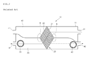
- Figure 1 is a plane view of a ventilator for describing the operation of a conventional ventilator
- Figure 2 is a cross sectional view taken along line I-I' of Figure 2.
- a conventional ventilator 10 includes a casing 11 forming an outer construction, an air supply suction part 31 formed in one surface of the casing 11 for sucking outdoor air, a suction duct 33 for sucking outdoor air sucked through the air supply suction part 31, and an air supply discharge part 32 for discharging outdoor air into an indoor.
- an exhaust suction part 41 is formed in one surface of the casing 11 for sucking indoor air. The indoor air sucked through the exhaust suction part 41 is flown by an exhaust duct 43.
- An exhaust discharge part 42 discharges the indoor air to the outdoor.
- a suction fan 30 installed in the air supply suction part 31 and the air supply discharge part 32 for sucking indoor air
- an exhaust fan 40 installed in a flow path connecting the exhaust part 41 and the exhaust discharge part 42 for sucking indoor air.
- the total heat exchanger 20 includes a suction air flow path 21 for flowing outdoor air, and an exhaust flow path 22 for flowing indoor air.
- the suction air flow path 21 and the exhaust flow path 22 are alternately formed in a layer structure with a partition wall therebetween, that outdoor air and indoor air are not mixed during heat exchange.
- the heat exchange is achieved in such a manner that the outdoor and indoor air inputted through the outdoor and indoor sides are not mixed with each other when they pass through the suction air flow path 21 and the exhaust flow path 22 of the total heat exchanger 20.
- the total heat exchanger 20 has a lateral cross section of a diamond shape and is longitudinally extended in a horizontal direction.
- the sucked outdoor and indoor air are inputted along a lower slanted surface of the total heat exchanger 20 and are discharged along the upper side slanted surface.
- the sucked outdoor and indoor are inputted along the upper side slanted surface and are discharged along the lower side slanted surface.
- the conventional ventilator since the total heat exchanger 20 is arranged in a diamond shape, the conventional ventilator has the following problems.
- the cross section dimension of the total heat exchanger has a certain limit. Therefore, it is impossible to make the cross section of the total heat exchange larger.
- the size of the total heat exchanger is increased.
- the airflow path passing through the total heat exchanger is bent at many points, so that the resistance of the flow path is increased.
- the air inputted eccentrically inputted in the left or right direction in the total heat exchanger does not reach at the opposite suction air flow path 21 or the exhaust flow path 22, so that a dead zone is formed wherein the efficiency of heat exchange is sharply decreased therein. Since the heat exchange is not actually performed in the dead zone, the efficiency of the heat exchange of the total heat exchanger 20 is decreased.
- a dead zone is not formed in the interior of a total heat exchanger in such a manner that air is uniformly flown in the entire flow paths in a horizontal direction of a total heat exchanger.
- a ventilator comprising a casing; a flow path that is formed in the interior of the casing wherein indoor air and/or outdoor air are sucked and discharged through the flow path; and a total heat exchanger that is connected with the flow path wherein the indoor air and/or outdoor flow through a plurality of channels horizontally extended, and the upper and lower sides of the total heat exchanger are blocked.
- Figure 1 is a plane view of a ventilator for describing the operation of a conventional ventilator
- Figure 2 is a cross sectional view taken along line I-I' of Figure 2
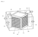
- Figure 3 is a schematic perspective view of a ventilator according to a first embodiment of the present invention
- Figure 4 is a perspective view illustrating a total heat exchanger according to the present invention
- Figure 5 is an enlarged view of the portion C of Figure 4
- Figure 6 is a plane view illustrating the operation of the ventilator according to the present invention
- Figure 7 is a plane view of a ventilator according to a second embodiment of the present invention
- Figure 8 is a plane view of a ventilator according to a third embodiment of the present invention
- Figure 9 is a plane view illustrating a ventilator according to a fourth embodiment of the present invention.
- Figure 3 is a schematic perspective view of a ventilator according to a first embodiment of the present invention.
- the ventilator 100 includes a casing 110 that forms an outer construction of the ventilator and protects inner elements, the suction air suction part 120 that is provided in one surface of the casing 110 and sucks outdoor air, and an air suction discharge part 121 that is provided in the other surface of the casing 110 so that air sucked through the suction air suction part 120 is discharged to the indoor.
- a casing 110 that forms an outer construction of the ventilator and protects inner elements
- the suction air suction part 120 that is provided in one surface of the casing 110 and sucks outdoor air
- an air suction discharge part 121 that is provided in the other surface of the casing 110 so that air sucked through the suction air suction part 120 is discharged to the indoor.
- a total heat exchanger 200 is provided in a center portion of the ventilator 100 wherein the air inputted into the interior of the ventilator 100 through the suction air suction part 120 and the exhaust suction part 130 is crossed and heat-exchanged.
- a suction fan 140 and an exhaust fan 150 are installed in the interior of the ventilator 100, so that the outdoor air and indoor air forcibly flow thereby.
- a plurality of stacked channels are formed in the total heat exchanger 200 in the upper and lower directions.
- the proceeding directions of the flow path in which the channels are formed are crossed with each other in the vertical direction. Therefore, the flow path for the air sucked and the flow path for the air exhausted are not mixed.
- the channels are stacked in the total heat exchanger 200 in the upper and lower directions, it is easy to expand the area of heat exchange.
- the air flowing in the flow path does not turn in the upper and lower directions, but turn only in the horizontal direction, so that a flow path resistance by the flow of air is very small. Therefore, the resistance in airflow is very small, and the efficiency of the heat exchange is enhanced.
- the suction fan 140 for sucking outdoor air is operated, and the exhaust fan 150 for sucking indoor air is operated.
- the outdoor air and indoor air are inputted into the ventilator 100 through the suction air suction part 120 based on the operation of the suction fan 140.
- the indoor air is inputted into the interior of the ventilator 100 through the exhaust suction part 130 based on the operation of the exhaust fan 150.
- the indoor air and outdoor air inputted into the interior of the ventilator 100 perform a heat exchange operation, while passing through the total heat exchanger 200. At this time, since the flow path of the indoor air is filly separated from the flow path of the outdoor air, the indoor air and outdoor air are not mixed.
- the air sucked into the suction air suction part 120 is sucked only through the suction air suction part 280 of the total heat exchanger 200 having a rectangular cross section, and the air sucked through an exhaust suction part 130 is sucked only through an exhaust suction part 290 of the total heat exchanger 200 having a rectangular cross section. Therefore, since it is installed away from the flow path, a dead zone in which air does not flow well is not formed. In addition, since the channels in the total heat exchanger 200 are extended in the horizontal direction without any curves in the upper and lower directions, there is not airflow in the upper and lower directions, so that the resistances in the flow are not caused.
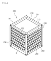
- Figure 4 is a perspective view illustrating a total heat exchanger according to the present invention
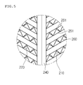
- Figure 5 is an enlarged view of the portion C of Figure 4.
- the total heat exchanger 200 has a hexahedral shape wherein air is sucked and discharged in a lateral direction. Namely, the air is sucked through the suction air suction part 280 and the exhaust suction part 290 formed in one side surface of the total heat exchanger 200, and the air is discharged through the opposite side of the same.
- the total heat exchanger 200 includes a rectangular plate shaped upper frame 230, a lateral frame 240 that is attached to four corners of the upper frame 230 and is vertically extended, and a lower frame 250 of which corners are attached to the ends of the other side of the lateral frame 240.
- a suction channel 210 and an exhaust channel 220 are alternately stacked between the upper frame 230 and the lower frame 250 in the upper and lower directions.
- the outdoor air is sucked and discharged through the suction channel 210, and the indoor air is sucked and discharged through the exhaust channel 220.
- the construction of the total heat exchanger 200 will be described.
- the suction air suction part 280 and the exhaust suction part 290 are formed in four corners of the lateral side of the total heat exchanger 200, and a suction discharge part 281 and an exhaust discharge part 291 are formed in the opposite lateral sides of the suction air suction part 280 and the exhaust suction part 290.
- Each channel 210 and 220 includes a heat exchange plate 261 in which a heat exchange is achieved between the outdoor air and indoor air based on a heat transfer operation, and a wrinkle plate 260 that is provided between the spaced-apart heat exchange plates 261 for thereby guiding the air to flow in a certain direction. Therefore, the heat exchange plate 261 is coupled to the upper side and lower side of the wrinkle plate 260.
- the wrinkle plate 260 allows the air to uniformly flow in the channels 210 and 220, so that the heat exchange is enhanced during the flow of air.
- the wrinkle plate 260 operates as fins capable of increasing the area of heat exchange, so that the heat exchange efficiency of the total heat exchanger is significantly enhanced.
- the wrinkle plate 260 is callable of increasing the total heat area with air for thereby transferring more heat.
- the winkle plate 260 and/or the heat exchange plate 2651 are formed of a certain metal having a high heat transfer coefficient, for example, an aluminum material.
- the construction of the wrinkle plate 260 is not limited to the embodiment of the present invention.
- the wrinkle plate with various shapes and widths may be adapted.
- the wrinkle plate 260 may be designed in such a manner that the air is sucked through the suction parts 280 and 290 in the interiors of the channels, and the air is discharged through the discharge parts 281 and 291.
- the suction channel 210 and the exhaust channel 220 are alternately stacked, so that the entrance for sucking the indoor air is crossed from the entrance for sucking the outdoor air. Therefore, the indoor air and outdoor air are crossed and flow in the interior of the total heat exchanger 200.
- the lateral side frame 240 faces the front and rear sides and both sides of the ventilator 100.
- suction terminal and discharge terminal have the same height, a multiple layer flow section does not occur in the flows of indoor and outdoor air sucked by the total heat exchanger 200 having the above-described construction. Therefore, it is possible to prevent any loss due to the flow resistance occurring during the flow of air. Even though the capacities of the suction fans 140 and 150 are small, it is possible to obtain a high efficiency. The consumption of energy may be decreased. It is possible to obtain high heat exchange efficiency by a small sized ventilator.
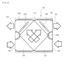
- Figure 6 is a plane view illustrating the operation of the ventilator according to the present invention.
- the ventilator 100 includes an exhaust flow path formed of the exhaust suction part 130, the exhaust suction duct 132, the total heat exchanger 200, the exhaust discharge duct 133, and the exhaust discharge part 131.
- a suction flow path formed of the suction part 120, the suction duct 122, the total heat exchanger 200, the suction discharge duct 123 and the suction discharge part 121.
- the suction flow path crosses with the exhaust flow path in a X shape.
- the suction air suction part 120 and the exhaust suction part 130 are the same horizontal line, and the discharge part 121 and the exhaust discharge part 131 are the same horizontal line by channel. Since the air flow path is formed like that, the length of the air flow is decreased, and the loss in flow is more decreased.
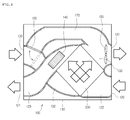
- Figure 7 is a plane view of a ventilator according to a second embodiment of the present invention. Since the second embodiment of the present invention is the same as the first embodiment of the present invention except for the construction of the duct, the detailed description will be omitted.
- the suction air discharge duct 123 and the exhaust suction duct 132 are crossed at a vertically distanced portion and are connected with the total heat exchanger 200.
- the suction air discharge duct 123 and the exhaust suction duct 132 are crossed in the interior of the ventilator 100 based on the characteristic of the fan.
- the suction fan 140 is a centrifugal fan like sirocco fan or turbo fan in which air is sucked in an axial direction and discharged in a radius direction, it is needed to minimize the resistance in air flow discharged from the suction fan 140.
- the direction of the airflow in the centrifugal fan is curved at 90° at the sides of inlet and outlet of the fan, it is needed to curve the direction of the flow path for thereby decreasing the resistance of airflow.
- the direction of the flow of the air discharged in a state that the direction of flow is curved at 90° by the centrifugal fan should be curved gain in the straight line direction.
- a lot of resistance occurs based on the inner shape of the duct, resulting a lot of noses.
- the suction air discharge duct 123 and the exhaust suction duct 132 are overlapped at the upper and lower positions, but the flow paths of the same are not mixed.
- the neighboring ducts should be obviously crossed with each other.
- FIG. 8 is a plane view of a ventilator according to a third embodiment of the present invention.
- the third embodiment of the present invention is the same as the second embodiment of the present invention except for the construction of a switching unit provided in the flow path. Therefore, the detailed description will be omitted except for the above different construction.
- the ventilator 100 further includes a ventilation duct 170 connected with the exhaust suction part 130 and the exhaust discharge part 131.
- a flow path switching unit 160 is further provided at an entrance of the exhaust suction part 130.
- the flow path switching unit is preferably provided near the exhaust suction part 130. If it is installed near the exhaust fan 150, the installation may be complicated. In addition, a certain problem may occur in the operation of the flow path switching unit 160 due to a turbulent flow near the exhaust fan 150.
- the exhaust fan 150 may be installed in any portion in the flow path in which the ventilation duct 170 is divided for thereby achieving a desired operation in the present invention.
- the flow path switching unit may includes a conventional damper, and a certain device may be adapted wherein it is rotatable with respect to a hinge point by a certain driving device.
- the ventilator according to the present invention may be operated in the total heat exchange mode or the conventional ventilation operation mode.
- the flow path switching unit 160 blocks the entrance of the ventilation duct 170, so that the indoor air flows through the total heat exchanger 200. At this time, since the heat exchange is performed by the total heat exchanger 200, the indoor temperature and moisture are constantly maintained together with the function of ventilation.
- a blower may be installed in the interior of the ventilation duct 170 for thereby achieving fast ventilation.
- Figure 9 is a plane view illustrating a ventilator according to a fourth embodiment of the present invention.
- the fourth embodiment of the present invention is the same as the second embodiment of the present invention except for the construction that the exhaust suction part is not on the same straight line as the exhaust discharge part, but is at the different position.
- the constructions not described in detail may be deemed similar with the constructions of the first and second embodiment of the present invention.
- the installation position of the exhaust suction part 130 for sucking the indoor air is not parallel with the exhaust discharge part 131, but is formed at a certain angle.
- the flow direction of the air sucked through the exhaust suction part 130 and the flow direction of the air discharged through the exhaust discharge part 131 are not parallel.
- the exhaust suction part 130 is formed in at a different position, so that the connection with a certain duct connected with the exhaust suction part 130 is easily achieved.
- connection terminals other preferred methods and positions may be easily adapted, so that the convenience of use is enhanced.
- the construction that the flow direction of the air is not parallel is not limited to the construction of the exhaust suction part 130. Namely, other suction parts and/or discharge parts may be installed with various directions based on the position that the ventilator 100 is installed.
- the suction air suction part and the suction air discharge part are installed on the same straight line in parallel, and the exhaust suction part and the exhaust discharge part are installed on the same straight line in parallel.
- the suction part and the discharge part may be installed in the other directions.
- the ventilator it is possible to make the ventilator smaller.
- the construction of flow structure is enhanced, for thereby enhancing a heat exchange efficiency.
Landscapes
- Engineering & Computer Science (AREA)
- General Engineering & Computer Science (AREA)
- Mechanical Engineering (AREA)
- Health & Medical Sciences (AREA)
- Physics & Mathematics (AREA)
- Combustion & Propulsion (AREA)
- Surgery (AREA)
- Life Sciences & Earth Sciences (AREA)
- Chemical & Material Sciences (AREA)
- Thermal Sciences (AREA)
- Biomedical Technology (AREA)
- Public Health (AREA)
- Veterinary Medicine (AREA)
- General Health & Medical Sciences (AREA)
- Animal Behavior & Ethology (AREA)
- Molecular Biology (AREA)
- Medical Informatics (AREA)
- Heart & Thoracic Surgery (AREA)
- Nuclear Medicine, Radiotherapy & Molecular Imaging (AREA)
- Heat-Exchange Devices With Radiators And Conduit Assemblies (AREA)
Applications Claiming Priority (2)
| Application Number | Priority Date | Filing Date | Title |
|---|---|---|---|
| KR2004034154 | 2004-05-14 | ||
| KR1020040034154A KR100590329B1 (ko) | 2004-05-14 | 2004-05-14 | 환기장치 |
Publications (2)
| Publication Number | Publication Date |
|---|---|
| EP1598607A2 true EP1598607A2 (de) | 2005-11-23 |
| EP1598607A3 EP1598607A3 (de) | 2007-01-31 |
Family
ID=34938916
Family Applications (1)
| Application Number | Title | Priority Date | Filing Date |
|---|---|---|---|
| EP05101746A Withdrawn EP1598607A3 (de) | 2004-05-14 | 2005-03-07 | Gebläse |
Country Status (3)
| Country | Link |
|---|---|
| US (2) | US20050252647A1 (de) |
| EP (1) | EP1598607A3 (de) |
| KR (1) | KR100590329B1 (de) |
Cited By (6)
| Publication number | Priority date | Publication date | Assignee | Title |
|---|---|---|---|---|
| EP2384109A4 (de) * | 2009-02-09 | 2013-07-31 | Panasonic Corp | Wärmetauschervorrichtung und erwärmungselementehalter damit |
| CN103398443A (zh) * | 2013-08-02 | 2013-11-20 | 重庆海润节能技术股份有限公司 | 一种洁净新风系统及洁风方法 |
| GB2513093A (en) * | 2013-02-08 | 2014-10-22 | Polypipe Ltd | Mechanical ventilation and heat recovery unit and system |
| EP2568229A3 (de) * | 2011-09-12 | 2018-04-25 | GEA Air Treatment GmbH | Wärmeaustauscher |
| EP3388769A1 (de) * | 2017-04-10 | 2018-10-17 | Hamilton Sundstrand Corporation | Wärmetauscherbaugruppe |
| GB2562674A (en) * | 2013-02-08 | 2018-11-21 | Polypipe Ltd | Mechanical ventilation and heat recovery unit and system |
Families Citing this family (20)
| Publication number | Priority date | Publication date | Assignee | Title |
|---|---|---|---|---|
| KR100628090B1 (ko) * | 2005-05-11 | 2006-09-26 | 엘지전자 주식회사 | 환기시스템 |
| KR100628058B1 (ko) * | 2005-05-31 | 2006-09-27 | 엘지전자 주식회사 | 전열교환기 및 이를 이용한 환기시스템 |
| KR20070019194A (ko) * | 2005-08-11 | 2007-02-15 | 엘지전자 주식회사 | 환기장치 |
| KR101070648B1 (ko) * | 2009-02-02 | 2011-10-07 | 인제대학교 산학협력단 | 공기식 열교환기 |
| KR100938802B1 (ko) * | 2009-06-11 | 2010-01-27 | 국방과학연구소 | 마이크로채널 열교환기 |
| TWM381055U (en) * | 2009-11-25 | 2010-05-21 | Asia Vital Components Co Ltd | Fin structure for heat exchanger and heat exchanger thereof |
| KR101362895B1 (ko) * | 2011-03-30 | 2014-02-14 | 주식회사 윈드림 | 환기장치용 열교환기 |
| KR101364240B1 (ko) * | 2011-05-12 | 2014-02-14 | 주식회사 윈드림 | 확장된 열교환기를 구비한 환기장치 |
| KR101440723B1 (ko) * | 2013-03-14 | 2014-09-17 | 정인숙 | 현열교환기, 이를 포함하는 열회수 환기장치, 및 그 해빙운전과 점검운전 방법 |
| RU2539668C2 (ru) * | 2013-04-18 | 2015-01-20 | Владимир Евгеньевич Воскресенский | Приточно-вытяжная установка с рекуперацией теплоты вытяжного воздуха и косвенным адиабатическим охлаждением приточного воздуха |
| CA2929856C (en) | 2013-11-18 | 2020-02-25 | General Electric Company | Monolithic tube-in matrix heat exchanger |
| CN105765311B (zh) | 2013-11-26 | 2019-03-08 | 松下知识产权经营株式会社 | 供排型换气装置 |
| JP6259997B2 (ja) * | 2013-11-26 | 2018-01-17 | パナソニックIpマネジメント株式会社 | 給排型換気装置 |
| CN109028332A (zh) * | 2018-07-05 | 2018-12-18 | 杨平 | 一种基于热交换器的空气过滤装置 |
| CN110006278A (zh) * | 2019-05-08 | 2019-07-12 | 科林贝思(深圳)科技有限公司 | 一种全热换热器 |
| KR102199435B1 (ko) * | 2019-08-06 | 2021-01-07 | 권우현 | 전열 교환장치 |
| CN113494741B (zh) * | 2021-07-09 | 2024-09-20 | 珠海格力电器股份有限公司 | 新风机除水结构、新风机和新风机除水控制方法及装置 |
| CN114526546A (zh) * | 2021-11-14 | 2022-05-24 | 肖正广 | 逆流式高效节能新风机热交换器芯体 |
| KR102806365B1 (ko) * | 2022-07-18 | 2025-05-13 | 엘지전자 주식회사 | 환기 장치 |
| KR20250070888A (ko) | 2023-11-14 | 2025-05-21 | 신연호 | 환기 장치 |
Family Cites Families (11)
| Publication number | Priority date | Publication date | Assignee | Title |
|---|---|---|---|---|
| DE3112394A1 (de) * | 1980-07-22 | 1982-07-08 | Eltreva AG, 4147 Aesch | "einrichtung zur luftregulierung einer energiefassade" |
| US4820468A (en) * | 1985-03-22 | 1989-04-11 | Hartig Martval J | Method for making welded hollow plastic plate heat exchangers |
| JPH063310B2 (ja) * | 1988-06-29 | 1994-01-12 | 三菱電機株式会社 | 熱交換器付換気装置 |
| US4971137A (en) * | 1989-11-09 | 1990-11-20 | American Energy Exchange, Inc. | Air-to-air heat exchanger with frost preventing means |
| DE4002560C2 (de) * | 1990-01-30 | 1995-07-20 | Stiebel Eltron Gmbh & Co Kg | Klimagerät |
| GB2296968A (en) * | 1994-12-02 | 1996-07-17 | Thermal Technology | Heat exchange ventilator |
| DE19534842C2 (de) * | 1995-09-20 | 1998-04-16 | Sks Stakusit Kunststoff Gmbh | Vorrichtung zum Be- und Entlüften von Räumen |
| DE29801169U1 (de) * | 1998-01-24 | 1998-03-26 | Klimatec GmbH, 54294 Trier | Vorrichtung zum Erwärmen oder Abkühlen eines Luftstromes mittels eines weiteren Luftstromes |
| KR20010098172A (ko) * | 2000-04-28 | 2001-11-08 | 김광수 | 댐퍼장치가 구비된 실내환기장치 |
| JP3969064B2 (ja) * | 2001-11-16 | 2007-08-29 | 三菱電機株式会社 | 熱交換器及び熱交換換気装置 |
| KR100789810B1 (ko) * | 2002-01-24 | 2007-12-28 | 엘지전자 주식회사 | 환기장치 |
-
2004
- 2004-05-14 KR KR1020040034154A patent/KR100590329B1/ko not_active Expired - Fee Related
- 2004-08-10 US US10/914,086 patent/US20050252647A1/en not_active Abandoned
-
2005
- 2005-03-07 EP EP05101746A patent/EP1598607A3/de not_active Withdrawn
-
2006
- 2006-07-31 US US11/495,761 patent/US20060260791A1/en not_active Abandoned
Cited By (10)
| Publication number | Priority date | Publication date | Assignee | Title |
|---|---|---|---|---|
| EP2384109A4 (de) * | 2009-02-09 | 2013-07-31 | Panasonic Corp | Wärmetauschervorrichtung und erwärmungselementehalter damit |
| EP2568229A3 (de) * | 2011-09-12 | 2018-04-25 | GEA Air Treatment GmbH | Wärmeaustauscher |
| GB2513093A (en) * | 2013-02-08 | 2014-10-22 | Polypipe Ltd | Mechanical ventilation and heat recovery unit and system |
| GB2513093B (en) * | 2013-02-08 | 2018-10-17 | Polypipe Ltd | Mechanical ventilation and heat recovery unit and system |
| GB2562674A (en) * | 2013-02-08 | 2018-11-21 | Polypipe Ltd | Mechanical ventilation and heat recovery unit and system |
| GB2562674B (en) * | 2013-02-08 | 2019-03-06 | Polypipe Ltd | Mechanical ventilation and heat recovery unit and system |
| CN103398443A (zh) * | 2013-08-02 | 2013-11-20 | 重庆海润节能技术股份有限公司 | 一种洁净新风系统及洁风方法 |
| CN103398443B (zh) * | 2013-08-02 | 2016-01-20 | 重庆海润节能技术股份有限公司 | 一种洁净新风系统及洁风方法 |
| EP3388769A1 (de) * | 2017-04-10 | 2018-10-17 | Hamilton Sundstrand Corporation | Wärmetauscherbaugruppe |
| CN108692593A (zh) * | 2017-04-10 | 2018-10-23 | 哈米尔顿森德斯特兰德公司 | 热交换器组件 |
Also Published As
| Publication number | Publication date |
|---|---|
| KR20050108911A (ko) | 2005-11-17 |
| KR100590329B1 (ko) | 2006-06-19 |
| EP1598607A3 (de) | 2007-01-31 |
| US20050252647A1 (en) | 2005-11-17 |
| US20060260791A1 (en) | 2006-11-23 |
Similar Documents
| Publication | Publication Date | Title |
|---|---|---|
| EP1598607A2 (de) | Gebläse | |
| KR100651879B1 (ko) | 환기시스템 | |
| KR101085899B1 (ko) | 공기조화기 | |
| KR102106702B1 (ko) | 전열교환기 | |
| EP1939574A1 (de) | Belüftungsvorrichtung, Wärmetauschvorrichtung und Wärmetauschelement sowie Rippe dafür | |
| CN115164280A (zh) | 立式空调室内机 | |
| KR100617078B1 (ko) | 콤팩트형 환기시스템 | |
| JP2000249360A (ja) | 3面吐出型空気調和機 | |
| WO2010097883A1 (ja) | 同時給排形換気扇および空調装置 | |
| CN217685368U (zh) | 空调室内机 | |
| JP3661471B2 (ja) | 空気調和機 | |
| CN101165416A (zh) | 换气装置 | |
| KR101459218B1 (ko) | 대향류형 열교환기를 장착한 열회수 환기시스템 | |
| CN1766439B (zh) | 换气装置 | |
| JP2005195199A (ja) | 空気調和機 | |
| CN217685353U (zh) | 空调室内机 | |
| JPH09280644A (ja) | セパレート型空気調和機 | |
| CN116608509A (zh) | 立式空调室内机 | |
| EP1052457B1 (de) | Innenraumeinheit einer klimaanlage | |
| JP3758592B2 (ja) | 天井埋込形空気調和機 | |
| CN217685369U (zh) | 空调室内机 | |
| KR100542941B1 (ko) | 환기장치용 열교환기 | |
| CN116972448A (zh) | 空调器的控制方法 | |
| KR100565834B1 (ko) | 환기장치용 열교환기 | |
| KR102922946B1 (ko) | 스탠드형 전열교환 환기장치 |
Legal Events
| Date | Code | Title | Description |
|---|---|---|---|
| PUAI | Public reference made under article 153(3) epc to a published international application that has entered the european phase |
Free format text: ORIGINAL CODE: 0009012 |
|
| AK | Designated contracting states |
Kind code of ref document: A2 Designated state(s): AT BE BG CH CY CZ DE DK EE ES FI FR GB GR HU IE IS IT LI LT LU MC NL PL PT RO SE SI SK TR |
|
| AX | Request for extension of the european patent |
Extension state: AL BA HR LV MK YU |
|
| PUAL | Search report despatched |
Free format text: ORIGINAL CODE: 0009013 |
|
| AK | Designated contracting states |
Kind code of ref document: A3 Designated state(s): AT BE BG CH CY CZ DE DK EE ES FI FR GB GR HU IE IS IT LI LT LU MC NL PL PT RO SE SI SK TR |
|
| AX | Request for extension of the european patent |
Extension state: AL BA HR LV MK YU |
|
| 17P | Request for examination filed |
Effective date: 20070713 |
|
| AKX | Designation fees paid |
Designated state(s): DE FR GB |
|
| 17Q | First examination report despatched |
Effective date: 20080416 |
|
| STAA | Information on the status of an ep patent application or granted ep patent |
Free format text: STATUS: THE APPLICATION IS DEEMED TO BE WITHDRAWN |
|
| 18D | Application deemed to be withdrawn |
Effective date: 20120620 |