EP1598532A1 - Schmiervorrichtung für eine Brennkraftmaschine - Google Patents
Schmiervorrichtung für eine Brennkraftmaschine Download PDFInfo
- Publication number
- EP1598532A1 EP1598532A1 EP05291063A EP05291063A EP1598532A1 EP 1598532 A1 EP1598532 A1 EP 1598532A1 EP 05291063 A EP05291063 A EP 05291063A EP 05291063 A EP05291063 A EP 05291063A EP 1598532 A1 EP1598532 A1 EP 1598532A1
- Authority
- EP
- European Patent Office
- Prior art keywords
- oil
- reservoir
- tank
- engine
- return
- Prior art date
- Legal status (The legal status is an assumption and is not a legal conclusion. Google has not performed a legal analysis and makes no representation as to the accuracy of the status listed.)
- Granted
Links
- 230000001050 lubricating effect Effects 0.000 title description 8
- 230000005484 gravity Effects 0.000 claims abstract description 9
- 238000002485 combustion reaction Methods 0.000 claims abstract description 5
- 238000005461 lubrication Methods 0.000 claims description 9
- 238000011144 upstream manufacturing Methods 0.000 claims description 5
- 230000001105 regulatory effect Effects 0.000 claims description 3
- 239000003921 oil Substances 0.000 description 65
- 238000009795 derivation Methods 0.000 description 2
- 230000000694 effects Effects 0.000 description 2
- 230000015556 catabolic process Effects 0.000 description 1
- 239000000446 fuel Substances 0.000 description 1
- 238000003306 harvesting Methods 0.000 description 1
- 239000010687 lubricating oil Substances 0.000 description 1
- 210000000056 organ Anatomy 0.000 description 1
Images
Classifications
-
- F—MECHANICAL ENGINEERING; LIGHTING; HEATING; WEAPONS; BLASTING
- F01—MACHINES OR ENGINES IN GENERAL; ENGINE PLANTS IN GENERAL; STEAM ENGINES
- F01M—LUBRICATING OF MACHINES OR ENGINES IN GENERAL; LUBRICATING INTERNAL COMBUSTION ENGINES; CRANKCASE VENTILATING
- F01M5/00—Heating, cooling, or controlling temperature of lubricant; Lubrication means facilitating engine starting
- F01M5/005—Controlling temperature of lubricant
-
- F—MECHANICAL ENGINEERING; LIGHTING; HEATING; WEAPONS; BLASTING
- F01—MACHINES OR ENGINES IN GENERAL; ENGINE PLANTS IN GENERAL; STEAM ENGINES
- F01M—LUBRICATING OF MACHINES OR ENGINES IN GENERAL; LUBRICATING INTERNAL COMBUSTION ENGINES; CRANKCASE VENTILATING
- F01M1/00—Pressure lubrication
- F01M1/12—Closed-circuit lubricating systems not provided for in groups F01M1/02 - F01M1/10
-
- F—MECHANICAL ENGINEERING; LIGHTING; HEATING; WEAPONS; BLASTING
- F01—MACHINES OR ENGINES IN GENERAL; ENGINE PLANTS IN GENERAL; STEAM ENGINES
- F01M—LUBRICATING OF MACHINES OR ENGINES IN GENERAL; LUBRICATING INTERNAL COMBUSTION ENGINES; CRANKCASE VENTILATING
- F01M11/00—Component parts, details or accessories, not provided for in, or of interest apart from, groups F01M1/00 - F01M9/00
- F01M11/06—Means for keeping lubricant level constant or for accommodating movement or position of machines or engines
- F01M11/061—Means for keeping lubricant level constant
-
- F—MECHANICAL ENGINEERING; LIGHTING; HEATING; WEAPONS; BLASTING
- F01—MACHINES OR ENGINES IN GENERAL; ENGINE PLANTS IN GENERAL; STEAM ENGINES
- F01M—LUBRICATING OF MACHINES OR ENGINES IN GENERAL; LUBRICATING INTERNAL COMBUSTION ENGINES; CRANKCASE VENTILATING
- F01M11/00—Component parts, details or accessories, not provided for in, or of interest apart from, groups F01M1/00 - F01M9/00
- F01M11/0004—Oilsumps
-
- F—MECHANICAL ENGINEERING; LIGHTING; HEATING; WEAPONS; BLASTING
- F01—MACHINES OR ENGINES IN GENERAL; ENGINE PLANTS IN GENERAL; STEAM ENGINES
- F01M—LUBRICATING OF MACHINES OR ENGINES IN GENERAL; LUBRICATING INTERNAL COMBUSTION ENGINES; CRANKCASE VENTILATING
- F01M5/00—Heating, cooling, or controlling temperature of lubricant; Lubrication means facilitating engine starting
- F01M5/02—Conditioning lubricant for aiding engine starting, e.g. heating
- F01M5/021—Conditioning lubricant for aiding engine starting, e.g. heating by heating
- F01M2005/023—Oil sump with partition for facilitating heating of oil during starting
-
- F—MECHANICAL ENGINEERING; LIGHTING; HEATING; WEAPONS; BLASTING
- F01—MACHINES OR ENGINES IN GENERAL; ENGINE PLANTS IN GENERAL; STEAM ENGINES
- F01M—LUBRICATING OF MACHINES OR ENGINES IN GENERAL; LUBRICATING INTERNAL COMBUSTION ENGINES; CRANKCASE VENTILATING
- F01M11/00—Component parts, details or accessories, not provided for in, or of interest apart from, groups F01M1/00 - F01M9/00
- F01M11/0004—Oilsumps
- F01M2011/0083—Dry sumps
-
- F—MECHANICAL ENGINEERING; LIGHTING; HEATING; WEAPONS; BLASTING
- F01—MACHINES OR ENGINES IN GENERAL; ENGINE PLANTS IN GENERAL; STEAM ENGINES
- F01M—LUBRICATING OF MACHINES OR ENGINES IN GENERAL; LUBRICATING INTERNAL COMBUSTION ENGINES; CRANKCASE VENTILATING
- F01M2250/00—Measuring
- F01M2250/60—Operating parameters
Definitions
- the invention relates to a lubricating device for an internal combustion engine.
- the invention relates more particularly to a device for lubrication for an internal combustion engine comprising a first oil tank a second oil tank, means of connection between the first and the second tank allowing a return of oil from the second tank to the first tank, means of aspiration of the oil into the first tank, a first circulation loop oil sucked into the engine, means of determination of the temperature of the oil, means of selective diversion of at least part of the oil circulation in the first loop towards the second tank in depending on the temperature of the oil.
- Such a device is known in particular from document EP 0 132.
- This device includes a first oil reservoir under the engine and a second oil tank that is separated from the engine.
- the first tank is put in communication with inside the engine by a first loop of implementation circulation of the oil sucked by an oil pump into the first tank.
- On this first loop of implementation circulation is connected, upstream of the engine, a second oil diversion loop to derive oil in the second tank.
- a valve located on the second loop, allows to derive oil only when the temperature of the aspirated oil is greater than a predetermined value.
- the return of the oil from the second tank to the first tank is carried out by a system comprising means of determination of the oil level in the first tank and valves allowing oil return depending on the level of oil in the first tank.
- An object of the present invention is to mitigate all or part of the disadvantages of the prior art noted above.
- the lubricating device according to the invention is essentially characterized in that that the second tank is substantially under pressure atmospheric and in that the means of connection have an overflow system allowing return of oil from the second tank to the first tank by gravity.
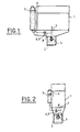
- the lubrication device of a combustion engine 1 shown in Figures 1 to 4 in different modes of realization comprises a first tank 2 of oil of lubrication located under the engine 1. This tank is intended in particular to harvest the lubricating oil circulating in the engine 1. Oil suction means 5, comprising usually an oil pump, are arranged in the first tank 2. The aspirated oil is circulated to the engine 1 in a first circulation loop 7. After lubrication of various mechanical parts of the engine, the oil descends heated by the organs via inside the engine 1 to the first tank 2.
- Selective branching means 8, 9 are connected to the first circulation loop 7, for example in upstream of the engine 1 or even at the level of the engine 1, preferably at the breech.
- selective branching means 8, 9 are connected to the first circulation loop 7 so as to allow a bypass of the oil sucked under pressure.
- the means of 8, 9 include a branch branch 8 which has a first end connected to the first loop 7 and a second end connected to a second tank 3.
- the branch 8 is connected directly to the second reservoir 3 at the lower end, preferably the bottom thereof, as shown in the figures.
- the selective diversion means 8, 9 comprise also a valve 9 for regulating the flow of the derived oil.
- valve 9 for regulating the flow of the derived oil.
- different types of valves such as electrical or thermal control, can be used.
- the valve 9 is located on the branch of derivation 8.
- the valve 9 does not allow an oil passage of the first 2 towards the second 3 tank only when the temperature of the oil of the first tank 2 is greater than a temperature predetermined.
- means for determining the temperature 6 determine the temperature of the oil sucked either before the suction in the first tank 2 or after aspiration.
- a thermovalve can be used which combines the means for determining the temperature 6 with the function valve 9, as shown in the figures.
- the second tank 3, in which part the oil can be derived, can be separated from the engine 1 (see Figures 1 and 3) or adjacent to the engine 1 (see for example Figures 2 and 4). In the case of a second tank 3 adjacent to the engine 1, this tank can for example be integrated into the engine block and: or at the breech, advantageously at a side face of the engine 1.
- the second tank 3 is a volume tank constant which is substantially under pressure atmospheric.
- the lubricating device according to the invention comprises connection means 4 between the first 2 and the second 3 tank allowing a return of oil by gravity from the second 3 to the first 2 tank.
- the return gravity oil is provided by relative altitudes the two tanks 2 and 3 and their means of 4.
- the second tank 3 and the junction between the second tank 3 and the means of connection 4 are located above the first tank 2,
- the return of gravity oil is provided by a overflow system.
- the derived oil arrives in the second tank 3, the volume and thus the oil level increase 3. When the oil level exceeds one certain predetermined level defined by the overflow system, the excess oil is donated under the effect of gravity at the first tank 2.
- the second tank 3 has a capacity higher oil than the first tank 2.
- the first tank 2 can hold two liters of oil and the second 3 four liters. This reduces the volume of the first tank 2 and so the clutter of the entire engine 1.
- the first reservoir is arranged so as to allow a reduction in the height of the entire engine.
- the lubricating device according to the invention allows a increasing the total oil volume and so allows spacing the empties.
- connection means 4 comprise, besides the overflow system, a conduit directly connecting the first 2 to second 3 tank.
- the embodiments shown in Figures 2 and 4 do not use ducts for connect the second 3 to the first 2 tank.
- Modes of embodiment of FIGS. 2 and 4 use the interior of the motor 1 as connecting means 4.
- the overflow system is advantageously arranged so as to create a communication between the second tank 3 and inside the engine 1.
- the oil return is made from way to lower the oil, for example, along the walls inside the engine 1 to the first tank 2.
- connection modes allowing the return of the oil from the second 3 to the first 2 tank.
- oil return can be provided either via the inside of the motor 1, either via a the outside of the engine 1 or by a combination of these two modes.
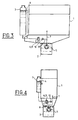
- FIGS. and 4 show variants respectively embodiments illustrated in FIGS. and 2.
- the elements identical to those of the described embodiments above are designated by the same reference numbers and are not described a second time in detail.
- the variants of Figures 3 and 4 are distinguished from the achievements described above only at the level of the means of derivation 8.9.
- the valve 9 is a valve three ways to either derive oil to the second reservoir 3, or to pour back derived oil directly into the first tank 2.
- the flap of discharge 10 is usually integrated with the oil pump 5, but it is also possible to mount it separately, for example at the level of the diversion means 8, upstream of the valve 9.
- the lubricating device according to the invention described above presents a simple and inexpensive structure. More particularly, it allows optimized regulation of oil exchanges between the first 2 and the second 3 tank guaranteeing optimum oil temperature rise for the operation of the engine 1.
- the device according to the invention makes it possible to quickly reach a temperature optimal for the operation of the engine 1, especially when from a cold start, which leads to a reduction in the fuel consumption.
- this lubrication device guarantees through its oil return system from the second 3 to the first 2 tank an optimized amount of oil in the first 2. In this way, the lubricating device according to the invention considerably reduces the risk of breakdowns to a lack of oil in the first tank.
- the system of oil return according to the invention also allows the use single point for the filling of the first 2 and the second 3 tank. When, filling in the second tank 3, the oil level exceeds the predetermined level defined by the overflow system, the excess oil is reversed under the effect of gravity in the first tank 2 and so fills it.
Landscapes
- Engineering & Computer Science (AREA)
- Mechanical Engineering (AREA)
- General Engineering & Computer Science (AREA)
- Lubrication Details And Ventilation Of Internal Combustion Engines (AREA)
- Lubrication Of Internal Combustion Engines (AREA)
Applications Claiming Priority (2)
| Application Number | Priority Date | Filing Date | Title |
|---|---|---|---|
| FR0450987A FR2870565B1 (fr) | 2004-05-18 | 2004-05-18 | Dispositif de lubrification d'un moteur a combustion interne |
| FR0450987 | 2004-05-18 |
Publications (2)
| Publication Number | Publication Date |
|---|---|
| EP1598532A1 true EP1598532A1 (de) | 2005-11-23 |
| EP1598532B1 EP1598532B1 (de) | 2007-04-11 |
Family
ID=34942305
Family Applications (1)
| Application Number | Title | Priority Date | Filing Date |
|---|---|---|---|
| EP05291063A Expired - Lifetime EP1598532B1 (de) | 2004-05-18 | 2005-05-17 | Schmiervorrichtung für eine Brennkraftmaschine |
Country Status (4)
| Country | Link |
|---|---|
| EP (1) | EP1598532B1 (de) |
| AT (1) | ATE359433T1 (de) |
| DE (1) | DE602005000848T2 (de) |
| FR (1) | FR2870565B1 (de) |
Cited By (1)
| Publication number | Priority date | Publication date | Assignee | Title |
|---|---|---|---|---|
| FR3004753A1 (fr) * | 2013-04-23 | 2014-10-24 | Peugeot Citroen Automobiles Sa | Procede de montee rapide en temperature de l'huile d'un moteur thermique et carter d'huile |
Families Citing this family (2)
| Publication number | Priority date | Publication date | Assignee | Title |
|---|---|---|---|---|
| DE102008021255A1 (de) | 2008-04-29 | 2009-01-22 | Daimler Ag | Schmierstoffspeicherbehälter sowie Schmiertoffkreislauf |
| DE102017114394A1 (de) | 2017-06-28 | 2019-01-03 | Dr. Ing. H.C. F. Porsche Aktiengesellschaft | Verbrennungsmotor, Verfahren zu dessen Herstellung und Kraftfahrzeug |
Citations (5)
| Publication number | Priority date | Publication date | Assignee | Title |
|---|---|---|---|---|
| US3712420A (en) * | 1971-04-06 | 1973-01-23 | Mack Trucks | Engine lubrication system |
| JPS6166813A (ja) * | 1984-09-10 | 1986-04-05 | Nissan Motor Co Ltd | 内燃機関用オイルパン |
| DE3544724A1 (de) * | 1985-12-18 | 1987-06-19 | Volkswagen Ag | Behaelteranordnung fuer eine betriebsfluessigkeit einer brennkraftmaschine |
| DE4202572A1 (de) * | 1991-02-12 | 1992-08-13 | Volkswagen Ag | Schmier- und/oder kuehloelversorgung fuer eine maschine, insbesondere eine brennkraftmaschine |
| JPH10259707A (ja) * | 1996-10-31 | 1998-09-29 | Yamaha Motor Co Ltd | 4サイクルエンジン |
-
2004
- 2004-05-18 FR FR0450987A patent/FR2870565B1/fr not_active Expired - Fee Related
-
2005
- 2005-05-17 EP EP05291063A patent/EP1598532B1/de not_active Expired - Lifetime
- 2005-05-17 DE DE602005000848T patent/DE602005000848T2/de not_active Expired - Lifetime
- 2005-05-17 AT AT05291063T patent/ATE359433T1/de not_active IP Right Cessation
Patent Citations (5)
| Publication number | Priority date | Publication date | Assignee | Title |
|---|---|---|---|---|
| US3712420A (en) * | 1971-04-06 | 1973-01-23 | Mack Trucks | Engine lubrication system |
| JPS6166813A (ja) * | 1984-09-10 | 1986-04-05 | Nissan Motor Co Ltd | 内燃機関用オイルパン |
| DE3544724A1 (de) * | 1985-12-18 | 1987-06-19 | Volkswagen Ag | Behaelteranordnung fuer eine betriebsfluessigkeit einer brennkraftmaschine |
| DE4202572A1 (de) * | 1991-02-12 | 1992-08-13 | Volkswagen Ag | Schmier- und/oder kuehloelversorgung fuer eine maschine, insbesondere eine brennkraftmaschine |
| JPH10259707A (ja) * | 1996-10-31 | 1998-09-29 | Yamaha Motor Co Ltd | 4サイクルエンジン |
Non-Patent Citations (2)
| Title |
|---|
| PATENT ABSTRACTS OF JAPAN vol. 0102, no. 34 (M - 507) 14 August 1986 (1986-08-14) * |
| PATENT ABSTRACTS OF JAPAN vol. 1998, no. 14 31 December 1998 (1998-12-31) * |
Cited By (1)
| Publication number | Priority date | Publication date | Assignee | Title |
|---|---|---|---|---|
| FR3004753A1 (fr) * | 2013-04-23 | 2014-10-24 | Peugeot Citroen Automobiles Sa | Procede de montee rapide en temperature de l'huile d'un moteur thermique et carter d'huile |
Also Published As
| Publication number | Publication date |
|---|---|
| ATE359433T1 (de) | 2007-05-15 |
| FR2870565B1 (fr) | 2006-06-30 |
| FR2870565A1 (fr) | 2005-11-25 |
| DE602005000848T2 (de) | 2007-12-20 |
| DE602005000848D1 (de) | 2007-05-24 |
| EP1598532B1 (de) | 2007-04-11 |
Similar Documents
| Publication | Publication Date | Title |
|---|---|---|
| EP2801707B1 (de) | Schmierkreislauf eines Turbotriebwerks mit Überlaufventil für Windmilling | |
| FR2734602A1 (fr) | Installation d'alimentation en carburant d'un moteur a combustion interne et procede de mise en oeuvre | |
| FR2723985A1 (fr) | Systeme de pompe a huile | |
| FR2665731A1 (fr) | Systeme d'alimentation en fluide notamment pour equipement mobile a moteur. | |
| FR2607195A1 (fr) | Dispositif, tubulures et procede pour isoler un compresseur hors service d'un circuit | |
| FR2979004A1 (fr) | Systeme de combustible ayant une unite de controle de combustible et echangeur de chaleur | |
| FR2991733A1 (fr) | Dispositif de compression et systeme thermodynamique comprenant un tel dispositif de compression | |
| EP2818651A1 (de) | Kolbengesteuertes Überlaufventil | |
| EP1598532B1 (de) | Schmiervorrichtung für eine Brennkraftmaschine | |
| FR2905423A1 (fr) | Dispositif de distribution de liquide de refroidissement dans un moteur de vehicule automobile | |
| FR2848248A1 (fr) | Circuit de refroidissement de moteur a combustion interne | |
| EP1229218B1 (de) | Automatische Ölstandsteurungvorrichtung für eine Brennkraftmaschine | |
| CH616725A5 (en) | Supercharged internal combustion engine | |
| FR2816354A1 (fr) | Dispositif de lubrification pour moteur a combustion interne | |
| FR2667583A1 (fr) | Dispositif de puisage de liquide dans un reservoir a plusieurs compartiments et reservoir equipe d'un tel dispositif. | |
| FR3134152A1 (fr) | Un système à compresseurs multiples ayant des soupapes normalement ouvertes dans des raccordements d’équilibrage d’huile | |
| FR3035155A1 (fr) | Circuit de distribution de carburant de turbomachine a encombrement reduit | |
| EP0936347B1 (de) | Vorrichtung zür Erhöhung der Temperaturanstiegsgeschwindigkeit des Motoröls | |
| EP4069951B1 (de) | Öldekanter mit einer frischluftkammer | |
| EP1972764A1 (de) | Belüftungsvorrichtung eines Verbrennungsmotors, der mit einer Ölrücklaufsperre ausgestattet ist | |
| FR2844563A1 (fr) | Systeme d'huile perfectionne pour l'alimentation en huile des freins humides d'un tracteur | |
| EP0850791B1 (de) | Heizungssystem für den Fahrgastraum eines Kraftfahrzeuges mit Dieselmotor mit Direkteinspritzung | |
| FR3132753A1 (fr) | Un système à compresseurs multiples ayant des conduites d’équilibrage d’huile individuelles | |
| FR3114623A1 (fr) | Compresseur à spirales ayant un système d’injection d’huile | |
| EP0347272A1 (de) | Einrichtung zum Verbinden von zwei Teilen eines Fluidkreislaufes, von denen eines eine Flüssigkeit enthält |
Legal Events
| Date | Code | Title | Description |
|---|---|---|---|
| PUAI | Public reference made under article 153(3) epc to a published international application that has entered the european phase |
Free format text: ORIGINAL CODE: 0009012 |
|
| AK | Designated contracting states |
Kind code of ref document: A1 Designated state(s): AT BE BG CH CY CZ DE DK EE ES FI FR GB GR HU IE IS IT LI LT LU MC NL PL PT RO SE SI SK TR |
|
| AX | Request for extension of the european patent |
Extension state: AL BA HR LV MK YU |
|
| 17P | Request for examination filed |
Effective date: 20060512 |
|
| AKX | Designation fees paid |
Designated state(s): AT BE BG CH CY CZ DE DK EE ES FI FR GB GR HU IE IS IT LI LT LU MC NL PL PT RO SE SI SK TR |
|
| GRAP | Despatch of communication of intention to grant a patent |
Free format text: ORIGINAL CODE: EPIDOSNIGR1 |
|
| GRAS | Grant fee paid |
Free format text: ORIGINAL CODE: EPIDOSNIGR3 |
|
| GRAA | (expected) grant |
Free format text: ORIGINAL CODE: 0009210 |
|
| AK | Designated contracting states |
Kind code of ref document: B1 Designated state(s): AT BE BG CH CY CZ DE DK EE ES FI FR GB GR HU IE IS IT LI LT LU MC NL PL PT RO SE SI SK TR |
|
| PG25 | Lapsed in a contracting state [announced via postgrant information from national office to epo] |
Ref country code: FI Free format text: LAPSE BECAUSE OF FAILURE TO SUBMIT A TRANSLATION OF THE DESCRIPTION OR TO PAY THE FEE WITHIN THE PRESCRIBED TIME-LIMIT Effective date: 20070411 Ref country code: SI Free format text: LAPSE BECAUSE OF FAILURE TO SUBMIT A TRANSLATION OF THE DESCRIPTION OR TO PAY THE FEE WITHIN THE PRESCRIBED TIME-LIMIT Effective date: 20070411 |
|
| REG | Reference to a national code |
Ref country code: GB Ref legal event code: FG4D Free format text: NOT ENGLISH |
|
| REG | Reference to a national code |
Ref country code: CH Ref legal event code: EP |
|
| GBT | Gb: translation of ep patent filed (gb section 77(6)(a)/1977) |
Effective date: 20070411 |
|
| REG | Reference to a national code |
Ref country code: IE Ref legal event code: FG4D Free format text: LANGUAGE OF EP DOCUMENT: FRENCH |
|
| REF | Corresponds to: |
Ref document number: 602005000848 Country of ref document: DE Date of ref document: 20070524 Kind code of ref document: P |
|
| PG25 | Lapsed in a contracting state [announced via postgrant information from national office to epo] |
Ref country code: SE Free format text: LAPSE BECAUSE OF FAILURE TO SUBMIT A TRANSLATION OF THE DESCRIPTION OR TO PAY THE FEE WITHIN THE PRESCRIBED TIME-LIMIT Effective date: 20070711 |
|
| PG25 | Lapsed in a contracting state [announced via postgrant information from national office to epo] |
Ref country code: ES Free format text: LAPSE BECAUSE OF FAILURE TO SUBMIT A TRANSLATION OF THE DESCRIPTION OR TO PAY THE FEE WITHIN THE PRESCRIBED TIME-LIMIT Effective date: 20070722 |
|
| PG25 | Lapsed in a contracting state [announced via postgrant information from national office to epo] |
Ref country code: IS Free format text: LAPSE BECAUSE OF FAILURE TO SUBMIT A TRANSLATION OF THE DESCRIPTION OR TO PAY THE FEE WITHIN THE PRESCRIBED TIME-LIMIT Effective date: 20070811 |
|
| PG25 | Lapsed in a contracting state [announced via postgrant information from national office to epo] |
Ref country code: PT Free format text: LAPSE BECAUSE OF FAILURE TO SUBMIT A TRANSLATION OF THE DESCRIPTION OR TO PAY THE FEE WITHIN THE PRESCRIBED TIME-LIMIT Effective date: 20070911 |
|
| NLV1 | Nl: lapsed or annulled due to failure to fulfill the requirements of art. 29p and 29m of the patents act | ||
| PG25 | Lapsed in a contracting state [announced via postgrant information from national office to epo] |
Ref country code: PL Free format text: LAPSE BECAUSE OF FAILURE TO SUBMIT A TRANSLATION OF THE DESCRIPTION OR TO PAY THE FEE WITHIN THE PRESCRIBED TIME-LIMIT Effective date: 20070411 Ref country code: AT Free format text: LAPSE BECAUSE OF FAILURE TO SUBMIT A TRANSLATION OF THE DESCRIPTION OR TO PAY THE FEE WITHIN THE PRESCRIBED TIME-LIMIT Effective date: 20070411 |
|
| REG | Reference to a national code |
Ref country code: IE Ref legal event code: FD4D |
|
| BERE | Be: lapsed |
Owner name: PEUGEOT CITROEN AUTOMOBILES Effective date: 20070531 |
|
| PG25 | Lapsed in a contracting state [announced via postgrant information from national office to epo] |
Ref country code: DK Free format text: LAPSE BECAUSE OF FAILURE TO SUBMIT A TRANSLATION OF THE DESCRIPTION OR TO PAY THE FEE WITHIN THE PRESCRIBED TIME-LIMIT Effective date: 20070411 Ref country code: CZ Free format text: LAPSE BECAUSE OF FAILURE TO SUBMIT A TRANSLATION OF THE DESCRIPTION OR TO PAY THE FEE WITHIN THE PRESCRIBED TIME-LIMIT Effective date: 20070411 Ref country code: IE Free format text: LAPSE BECAUSE OF FAILURE TO SUBMIT A TRANSLATION OF THE DESCRIPTION OR TO PAY THE FEE WITHIN THE PRESCRIBED TIME-LIMIT Effective date: 20070411 Ref country code: MC Free format text: LAPSE BECAUSE OF NON-PAYMENT OF DUE FEES Effective date: 20070531 Ref country code: BG Free format text: LAPSE BECAUSE OF FAILURE TO SUBMIT A TRANSLATION OF THE DESCRIPTION OR TO PAY THE FEE WITHIN THE PRESCRIBED TIME-LIMIT Effective date: 20070711 Ref country code: NL Free format text: LAPSE BECAUSE OF FAILURE TO SUBMIT A TRANSLATION OF THE DESCRIPTION OR TO PAY THE FEE WITHIN THE PRESCRIBED TIME-LIMIT Effective date: 20070411 |
|
| PLBE | No opposition filed within time limit |
Free format text: ORIGINAL CODE: 0009261 |
|
| STAA | Information on the status of an ep patent application or granted ep patent |
Free format text: STATUS: NO OPPOSITION FILED WITHIN TIME LIMIT |
|
| PG25 | Lapsed in a contracting state [announced via postgrant information from national office to epo] |
Ref country code: SK Free format text: LAPSE BECAUSE OF FAILURE TO SUBMIT A TRANSLATION OF THE DESCRIPTION OR TO PAY THE FEE WITHIN THE PRESCRIBED TIME-LIMIT Effective date: 20070411 Ref country code: LT Free format text: LAPSE BECAUSE OF FAILURE TO SUBMIT A TRANSLATION OF THE DESCRIPTION OR TO PAY THE FEE WITHIN THE PRESCRIBED TIME-LIMIT Effective date: 20070411 |
|
| 26N | No opposition filed |
Effective date: 20080114 |
|
| PG25 | Lapsed in a contracting state [announced via postgrant information from national office to epo] |
Ref country code: BE Free format text: LAPSE BECAUSE OF NON-PAYMENT OF DUE FEES Effective date: 20070531 |
|
| REG | Reference to a national code |
Ref country code: GB Ref legal event code: 746 Effective date: 20080329 |
|
| PG25 | Lapsed in a contracting state [announced via postgrant information from national office to epo] |
Ref country code: GR Free format text: LAPSE BECAUSE OF FAILURE TO SUBMIT A TRANSLATION OF THE DESCRIPTION OR TO PAY THE FEE WITHIN THE PRESCRIBED TIME-LIMIT Effective date: 20070712 Ref country code: IT Free format text: LAPSE BECAUSE OF FAILURE TO SUBMIT A TRANSLATION OF THE DESCRIPTION OR TO PAY THE FEE WITHIN THE PRESCRIBED TIME-LIMIT Effective date: 20070411 |
|
| PG25 | Lapsed in a contracting state [announced via postgrant information from national office to epo] |
Ref country code: RO Free format text: LAPSE BECAUSE OF FAILURE TO SUBMIT A TRANSLATION OF THE DESCRIPTION OR TO PAY THE FEE WITHIN THE PRESCRIBED TIME-LIMIT Effective date: 20070411 |
|
| PG25 | Lapsed in a contracting state [announced via postgrant information from national office to epo] |
Ref country code: EE Free format text: LAPSE BECAUSE OF FAILURE TO SUBMIT A TRANSLATION OF THE DESCRIPTION OR TO PAY THE FEE WITHIN THE PRESCRIBED TIME-LIMIT Effective date: 20070411 |
|
| PG25 | Lapsed in a contracting state [announced via postgrant information from national office to epo] |
Ref country code: CY Free format text: LAPSE BECAUSE OF FAILURE TO SUBMIT A TRANSLATION OF THE DESCRIPTION OR TO PAY THE FEE WITHIN THE PRESCRIBED TIME-LIMIT Effective date: 20070411 |
|
| PG25 | Lapsed in a contracting state [announced via postgrant information from national office to epo] |
Ref country code: LU Free format text: LAPSE BECAUSE OF NON-PAYMENT OF DUE FEES Effective date: 20070517 |
|
| PG25 | Lapsed in a contracting state [announced via postgrant information from national office to epo] |
Ref country code: TR Free format text: LAPSE BECAUSE OF FAILURE TO SUBMIT A TRANSLATION OF THE DESCRIPTION OR TO PAY THE FEE WITHIN THE PRESCRIBED TIME-LIMIT Effective date: 20070411 Ref country code: HU Free format text: LAPSE BECAUSE OF FAILURE TO SUBMIT A TRANSLATION OF THE DESCRIPTION OR TO PAY THE FEE WITHIN THE PRESCRIBED TIME-LIMIT Effective date: 20071012 |
|
| REG | Reference to a national code |
Ref country code: CH Ref legal event code: PL |
|
| PG25 | Lapsed in a contracting state [announced via postgrant information from national office to epo] |
Ref country code: CH Free format text: LAPSE BECAUSE OF NON-PAYMENT OF DUE FEES Effective date: 20090531 Ref country code: LI Free format text: LAPSE BECAUSE OF NON-PAYMENT OF DUE FEES Effective date: 20090531 |
|
| PGFP | Annual fee paid to national office [announced via postgrant information from national office to epo] |
Ref country code: DE Payment date: 20120423 Year of fee payment: 8 |
|
| PGFP | Annual fee paid to national office [announced via postgrant information from national office to epo] |
Ref country code: GB Payment date: 20120423 Year of fee payment: 8 Ref country code: FR Payment date: 20120625 Year of fee payment: 8 |
|
| GBPC | Gb: european patent ceased through non-payment of renewal fee |
Effective date: 20130517 |
|
| PG25 | Lapsed in a contracting state [announced via postgrant information from national office to epo] |
Ref country code: DE Free format text: LAPSE BECAUSE OF NON-PAYMENT OF DUE FEES Effective date: 20131203 |
|
| REG | Reference to a national code |
Ref country code: DE Ref legal event code: R119 Ref document number: 602005000848 Country of ref document: DE Effective date: 20131203 |
|
| REG | Reference to a national code |
Ref country code: FR Ref legal event code: ST Effective date: 20140131 |
|
| PG25 | Lapsed in a contracting state [announced via postgrant information from national office to epo] |
Ref country code: GB Free format text: LAPSE BECAUSE OF NON-PAYMENT OF DUE FEES Effective date: 20130517 |
|
| PG25 | Lapsed in a contracting state [announced via postgrant information from national office to epo] |
Ref country code: FR Free format text: LAPSE BECAUSE OF NON-PAYMENT OF DUE FEES Effective date: 20130531 |