EP1598532A1 - Lubricating device for an engine - Google Patents
Lubricating device for an engine Download PDFInfo
- Publication number
- EP1598532A1 EP1598532A1 EP05291063A EP05291063A EP1598532A1 EP 1598532 A1 EP1598532 A1 EP 1598532A1 EP 05291063 A EP05291063 A EP 05291063A EP 05291063 A EP05291063 A EP 05291063A EP 1598532 A1 EP1598532 A1 EP 1598532A1
- Authority
- EP
- European Patent Office
- Prior art keywords
- oil
- reservoir
- tank
- engine
- return
- Prior art date
- Legal status (The legal status is an assumption and is not a legal conclusion. Google has not performed a legal analysis and makes no representation as to the accuracy of the status listed.)
- Granted
Links
Images
Classifications
-
- F—MECHANICAL ENGINEERING; LIGHTING; HEATING; WEAPONS; BLASTING
- F01—MACHINES OR ENGINES IN GENERAL; ENGINE PLANTS IN GENERAL; STEAM ENGINES
- F01M—LUBRICATING OF MACHINES OR ENGINES IN GENERAL; LUBRICATING INTERNAL COMBUSTION ENGINES; CRANKCASE VENTILATING
- F01M5/00—Heating, cooling, or controlling temperature of lubricant; Lubrication means facilitating engine starting
- F01M5/005—Controlling temperature of lubricant
-
- F—MECHANICAL ENGINEERING; LIGHTING; HEATING; WEAPONS; BLASTING
- F01—MACHINES OR ENGINES IN GENERAL; ENGINE PLANTS IN GENERAL; STEAM ENGINES
- F01M—LUBRICATING OF MACHINES OR ENGINES IN GENERAL; LUBRICATING INTERNAL COMBUSTION ENGINES; CRANKCASE VENTILATING
- F01M1/00—Pressure lubrication
- F01M1/12—Closed-circuit lubricating systems not provided for in groups F01M1/02 - F01M1/10
-
- F—MECHANICAL ENGINEERING; LIGHTING; HEATING; WEAPONS; BLASTING
- F01—MACHINES OR ENGINES IN GENERAL; ENGINE PLANTS IN GENERAL; STEAM ENGINES
- F01M—LUBRICATING OF MACHINES OR ENGINES IN GENERAL; LUBRICATING INTERNAL COMBUSTION ENGINES; CRANKCASE VENTILATING
- F01M11/00—Component parts, details or accessories, not provided for in, or of interest apart from, groups F01M1/00 - F01M9/00
- F01M11/06—Means for keeping lubricant level constant or for accommodating movement or position of machines or engines
- F01M11/061—Means for keeping lubricant level constant
-
- F—MECHANICAL ENGINEERING; LIGHTING; HEATING; WEAPONS; BLASTING
- F01—MACHINES OR ENGINES IN GENERAL; ENGINE PLANTS IN GENERAL; STEAM ENGINES
- F01M—LUBRICATING OF MACHINES OR ENGINES IN GENERAL; LUBRICATING INTERNAL COMBUSTION ENGINES; CRANKCASE VENTILATING
- F01M11/00—Component parts, details or accessories, not provided for in, or of interest apart from, groups F01M1/00 - F01M9/00
- F01M11/0004—Oilsumps
-
- F—MECHANICAL ENGINEERING; LIGHTING; HEATING; WEAPONS; BLASTING
- F01—MACHINES OR ENGINES IN GENERAL; ENGINE PLANTS IN GENERAL; STEAM ENGINES
- F01M—LUBRICATING OF MACHINES OR ENGINES IN GENERAL; LUBRICATING INTERNAL COMBUSTION ENGINES; CRANKCASE VENTILATING
- F01M5/00—Heating, cooling, or controlling temperature of lubricant; Lubrication means facilitating engine starting
- F01M5/02—Conditioning lubricant for aiding engine starting, e.g. heating
- F01M5/021—Conditioning lubricant for aiding engine starting, e.g. heating by heating
- F01M2005/023—Oil sump with partition for facilitating heating of oil during starting
-
- F—MECHANICAL ENGINEERING; LIGHTING; HEATING; WEAPONS; BLASTING
- F01—MACHINES OR ENGINES IN GENERAL; ENGINE PLANTS IN GENERAL; STEAM ENGINES
- F01M—LUBRICATING OF MACHINES OR ENGINES IN GENERAL; LUBRICATING INTERNAL COMBUSTION ENGINES; CRANKCASE VENTILATING
- F01M11/00—Component parts, details or accessories, not provided for in, or of interest apart from, groups F01M1/00 - F01M9/00
- F01M11/0004—Oilsumps
- F01M2011/0083—Dry sumps
-
- F—MECHANICAL ENGINEERING; LIGHTING; HEATING; WEAPONS; BLASTING
- F01—MACHINES OR ENGINES IN GENERAL; ENGINE PLANTS IN GENERAL; STEAM ENGINES
- F01M—LUBRICATING OF MACHINES OR ENGINES IN GENERAL; LUBRICATING INTERNAL COMBUSTION ENGINES; CRANKCASE VENTILATING
- F01M2250/00—Measuring
- F01M2250/60—Operating parameters
Definitions
- the invention relates to a lubricating device for an internal combustion engine.
- the invention relates more particularly to a device for lubrication for an internal combustion engine comprising a first oil tank a second oil tank, means of connection between the first and the second tank allowing a return of oil from the second tank to the first tank, means of aspiration of the oil into the first tank, a first circulation loop oil sucked into the engine, means of determination of the temperature of the oil, means of selective diversion of at least part of the oil circulation in the first loop towards the second tank in depending on the temperature of the oil.
- Such a device is known in particular from document EP 0 132.
- This device includes a first oil reservoir under the engine and a second oil tank that is separated from the engine.
- the first tank is put in communication with inside the engine by a first loop of implementation circulation of the oil sucked by an oil pump into the first tank.
- On this first loop of implementation circulation is connected, upstream of the engine, a second oil diversion loop to derive oil in the second tank.
- a valve located on the second loop, allows to derive oil only when the temperature of the aspirated oil is greater than a predetermined value.
- the return of the oil from the second tank to the first tank is carried out by a system comprising means of determination of the oil level in the first tank and valves allowing oil return depending on the level of oil in the first tank.
- An object of the present invention is to mitigate all or part of the disadvantages of the prior art noted above.
- the lubricating device according to the invention is essentially characterized in that that the second tank is substantially under pressure atmospheric and in that the means of connection have an overflow system allowing return of oil from the second tank to the first tank by gravity.
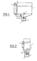
- the lubrication device of a combustion engine 1 shown in Figures 1 to 4 in different modes of realization comprises a first tank 2 of oil of lubrication located under the engine 1. This tank is intended in particular to harvest the lubricating oil circulating in the engine 1. Oil suction means 5, comprising usually an oil pump, are arranged in the first tank 2. The aspirated oil is circulated to the engine 1 in a first circulation loop 7. After lubrication of various mechanical parts of the engine, the oil descends heated by the organs via inside the engine 1 to the first tank 2.
- Selective branching means 8, 9 are connected to the first circulation loop 7, for example in upstream of the engine 1 or even at the level of the engine 1, preferably at the breech.
- selective branching means 8, 9 are connected to the first circulation loop 7 so as to allow a bypass of the oil sucked under pressure.
- the means of 8, 9 include a branch branch 8 which has a first end connected to the first loop 7 and a second end connected to a second tank 3.
- the branch 8 is connected directly to the second reservoir 3 at the lower end, preferably the bottom thereof, as shown in the figures.
- the selective diversion means 8, 9 comprise also a valve 9 for regulating the flow of the derived oil.
- valve 9 for regulating the flow of the derived oil.
- different types of valves such as electrical or thermal control, can be used.
- the valve 9 is located on the branch of derivation 8.
- the valve 9 does not allow an oil passage of the first 2 towards the second 3 tank only when the temperature of the oil of the first tank 2 is greater than a temperature predetermined.
- means for determining the temperature 6 determine the temperature of the oil sucked either before the suction in the first tank 2 or after aspiration.
- a thermovalve can be used which combines the means for determining the temperature 6 with the function valve 9, as shown in the figures.
- the second tank 3, in which part the oil can be derived, can be separated from the engine 1 (see Figures 1 and 3) or adjacent to the engine 1 (see for example Figures 2 and 4). In the case of a second tank 3 adjacent to the engine 1, this tank can for example be integrated into the engine block and: or at the breech, advantageously at a side face of the engine 1.
- the second tank 3 is a volume tank constant which is substantially under pressure atmospheric.
- the lubricating device according to the invention comprises connection means 4 between the first 2 and the second 3 tank allowing a return of oil by gravity from the second 3 to the first 2 tank.
- the return gravity oil is provided by relative altitudes the two tanks 2 and 3 and their means of 4.
- the second tank 3 and the junction between the second tank 3 and the means of connection 4 are located above the first tank 2,
- the return of gravity oil is provided by a overflow system.
- the derived oil arrives in the second tank 3, the volume and thus the oil level increase 3. When the oil level exceeds one certain predetermined level defined by the overflow system, the excess oil is donated under the effect of gravity at the first tank 2.
- the second tank 3 has a capacity higher oil than the first tank 2.
- the first tank 2 can hold two liters of oil and the second 3 four liters. This reduces the volume of the first tank 2 and so the clutter of the entire engine 1.
- the first reservoir is arranged so as to allow a reduction in the height of the entire engine.
- the lubricating device according to the invention allows a increasing the total oil volume and so allows spacing the empties.
- connection means 4 comprise, besides the overflow system, a conduit directly connecting the first 2 to second 3 tank.
- the embodiments shown in Figures 2 and 4 do not use ducts for connect the second 3 to the first 2 tank.
- Modes of embodiment of FIGS. 2 and 4 use the interior of the motor 1 as connecting means 4.
- the overflow system is advantageously arranged so as to create a communication between the second tank 3 and inside the engine 1.
- the oil return is made from way to lower the oil, for example, along the walls inside the engine 1 to the first tank 2.
- connection modes allowing the return of the oil from the second 3 to the first 2 tank.
- oil return can be provided either via the inside of the motor 1, either via a the outside of the engine 1 or by a combination of these two modes.
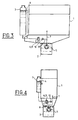
- FIGS. and 4 show variants respectively embodiments illustrated in FIGS. and 2.
- the elements identical to those of the described embodiments above are designated by the same reference numbers and are not described a second time in detail.
- the variants of Figures 3 and 4 are distinguished from the achievements described above only at the level of the means of derivation 8.9.
- the valve 9 is a valve three ways to either derive oil to the second reservoir 3, or to pour back derived oil directly into the first tank 2.
- the flap of discharge 10 is usually integrated with the oil pump 5, but it is also possible to mount it separately, for example at the level of the diversion means 8, upstream of the valve 9.
- the lubricating device according to the invention described above presents a simple and inexpensive structure. More particularly, it allows optimized regulation of oil exchanges between the first 2 and the second 3 tank guaranteeing optimum oil temperature rise for the operation of the engine 1.
- the device according to the invention makes it possible to quickly reach a temperature optimal for the operation of the engine 1, especially when from a cold start, which leads to a reduction in the fuel consumption.
- this lubrication device guarantees through its oil return system from the second 3 to the first 2 tank an optimized amount of oil in the first 2. In this way, the lubricating device according to the invention considerably reduces the risk of breakdowns to a lack of oil in the first tank.
- the system of oil return according to the invention also allows the use single point for the filling of the first 2 and the second 3 tank. When, filling in the second tank 3, the oil level exceeds the predetermined level defined by the overflow system, the excess oil is reversed under the effect of gravity in the first tank 2 and so fills it.
Landscapes
- Engineering & Computer Science (AREA)
- Mechanical Engineering (AREA)
- General Engineering & Computer Science (AREA)
- Lubrication Details And Ventilation Of Internal Combustion Engines (AREA)
- Lubrication Of Internal Combustion Engines (AREA)
Abstract
Description
L'invention se rapporte à un dispositif de lubrification pour un moteur à combustion interne.The invention relates to a lubricating device for an internal combustion engine.
L'invention concerne plus particulièrement un dispositif de lubrification pour un moteur à combustion interne comprenant un premier réservoir d'huile un second réservoir d'huile, des moyens de raccordement entre le premier et le second réservoir permettant un retour d'huile du second réservoir vers le premier réservoir, des moyens d'aspiration de l'huile dans le premier réservoir, une première boucle de mise en circulation de l'huile aspirée dans le moteur, des moyens de détermination de la température de l'huile, des moyens de dérivation sélective d'au moins une partie de l'huile mise en circulation dans la première boucle vers le second réservoir en fonction de la température de l'huile.The invention relates more particularly to a device for lubrication for an internal combustion engine comprising a first oil tank a second oil tank, means of connection between the first and the second tank allowing a return of oil from the second tank to the first tank, means of aspiration of the oil into the first tank, a first circulation loop oil sucked into the engine, means of determination of the temperature of the oil, means of selective diversion of at least part of the oil circulation in the first loop towards the second tank in depending on the temperature of the oil.
Un tel dispositif est connu notamment du document EP 0 188 132. Ce dispositif comporte un premier réservoir d'huile sous le moteur et un second réservoir d'huile qui est séparé du moteur. Le premier réservoir est mis en communication avec l'intérieur du moteur par une première boucle de mise en circulation de l'huile aspirée par une pompe à huile dans le premier réservoir. Sur cette première boucle de mise en circulation est branchée, en amont du moteur, une deuxième boucle de dérivation d'huile pour dériver de l'huile dans le second réservoir. Une vanne, situé sur la deuxième boucle, permet de ne dériver de l'huile que lorsque la température de l'huile aspirée est supérieure a une valeur prédéterminée. Le retour de l'huile du second réservoir vers le premier réservoir est effectué par un système comportant des moyens de détermination du niveau d'huile dans le premier réservoir et des vannes permettant le retour d'huile en fonction du niveau d'huile dans le premier réservoir. Such a device is known in particular from document EP 0 132. This device includes a first oil reservoir under the engine and a second oil tank that is separated from the engine. The first tank is put in communication with inside the engine by a first loop of implementation circulation of the oil sucked by an oil pump into the first tank. On this first loop of implementation circulation is connected, upstream of the engine, a second oil diversion loop to derive oil in the second tank. A valve, located on the second loop, allows to derive oil only when the temperature of the aspirated oil is greater than a predetermined value. The return of the oil from the second tank to the first tank is carried out by a system comprising means of determination of the oil level in the first tank and valves allowing oil return depending on the level of oil in the first tank.
Ce système s'avère très complexe et coûteux, notamment à cause de la multitude de pièces mécaniques et électriques nécessaires pour assurer le retour d'huile au premier réservoir. De plus, un système aussi complexe est fortement susceptible de tomber en panne ce qui peut avoir de conséquences graves pour le moteur.This system is very complex and expensive, especially because of the multitude of mechanical and electrical parts necessary to ensure the return of oil to the first tank. In addition, such a complex system is highly susceptible to break down which can have serious consequences for the engine.
Un but de la présente invention est de pallier tout ou partie des inconvénients de l'art antérieur relevés ci-dessus.An object of the present invention is to mitigate all or part of the disadvantages of the prior art noted above.
A cette fin, le dispositif de lubrification selon l'invention, par ailleurs conforme à la définition générique qu'en donne le préambule ci-dessus, est essentiellement caractérisé en ce que le second réservoir est sensiblement sous pression atmosphérique et en ce que les moyens de raccordements comportent un système de trop plein autorisant le retour d'huile du second réservoir vers le premier réservoir par gravité.For this purpose, the lubricating device according to the invention, otherwise consistent with the generic definition given in preamble above, is essentially characterized in that that the second tank is substantially under pressure atmospheric and in that the means of connection have an overflow system allowing return of oil from the second tank to the first tank by gravity.
Par ailleurs, l'invention peut comporter l'une ou plusieurs des caractéristiques suivantes:
- les moyens de dérivation sélective comprennent une branche de dérivation raccordée à la première boucle, en amont du moteur,
- les moyens de raccordement sont agencés de façon que le retour d'huile du second réservoir vers le premier réservoir s'effectue au moins en partie via l'intérieur du moteur,
- les moyens de dérivation sélective comportent une vanne régulant le débit de l'huile dérivée,
- que la vanne est une vanne à trois voies permettant soit de dériver de l'huile vers le second réservoir, soit de reverser de l'huile dérivée directement dans le premier réservoir,
- la vanne est une thermovanne intégrant les moyens de détermination de la température,
- le premier réservoir est disposé de façon adjacente au moteur, de préférence en partie basse du moteur,
- le second réservoir est séparé du moteur,
- le second réservoir est disposé de façon adjacente au moteur,
- le second réservoir est situé au niveau d'une face latérale du moteur.
- the selective diversion means comprise a bypass branch connected to the first loop, upstream of the motor,
- the connecting means are arranged in such a way that the oil return from the second reservoir to the first reservoir takes place at least partly via the inside of the engine,
- the selective diversion means comprise a valve regulating the flow rate of the derived oil,
- that the valve is a three-way valve for either drifting oil to the second tank or pouring derived oil directly into the first tank,
- the valve is a thermovalve incorporating the means for determining the temperature,
- the first reservoir is disposed adjacent to the engine, preferably at the bottom of the engine,
- the second tank is separated from the engine,
- the second tank is arranged adjacent to the engine,
- the second tank is located at a side face of the engine.
D'autres particularités et avantages apparaítront à la lecture de la description ci-après faite en référence aux figures dans lesquelles :
- la figure 1 représente une vue en coupe schématique d'un dispositif de lubrification selon un premier mode de réalisation,
- la figure 2 représente une vue en coupe schématique d'un dispositif de lubrification selon un second mode de réalisation,
- la figure 3 représente une vue en coupe schématique d'un dispositif de lubrification selon un troisième mode de réalisation,
- la figure 4 représente une vue en coupe schématique d'un dispositif de lubrification selon un quatrième mode de réalisation.
- FIG. 1 represents a schematic sectional view of a lubricating device according to a first embodiment,
- FIG. 2 represents a schematic sectional view of a lubrication device according to a second embodiment,
- FIG. 3 represents a schematic sectional view of a lubrication device according to a third embodiment,
- Figure 4 shows a schematic sectional view of a lubrication device according to a fourth embodiment.
Le dispositif de lubrification d'un moteur 1 à combustion
interne représenté aux figures 1 à 4 dans différents modes de
réalisation comporte un premier réservoir 2 d'huile de
lubrification situé sous le moteur 1. Ce réservoir est destiné
notamment à récolter l'huile de lubrification ayant circulé dans
le moteur 1. Des moyens d'aspiration d'huile 5, comprenant
habituellement une pompe à huile, sont disposé dans le
premier réservoir 2. L'huile aspirée est mise en circulation vers
le moteur 1 dans une première boucle 7 de mise en circulation.
Après lubrification de différents organes mécaniques du
moteur, l'huile descend réchauffée par les organes via
l'intérieur du moteur 1 vers le premier réservoir 2.The lubrication device of a
Des moyens de dérivation 8, 9 sélective sont branchés sur
la première boucle 7 de mise en circulation, par exemple en
amont du moteur 1 ou même au niveau du moteur 1, de
préférence au niveau de la culasse. Avantageusement les
moyens de dérivation 8, 9 sélective sont branchés sur la
première boucle 7 de mise en circulation de façon à permettre
une dérivation de l'huile aspirée sous pression. Les moyens de
dérivation 8, 9 comprennent une branche de dérivation 8 qui a
une première extrémité raccordée à la première boucle 7 et
une seconde extrémité racordée à un second réservoir 3.
Avantageusement, la branche 8 est connectée directement au
second réservoir 3 au niveau de l'extrémité inférieure, de
préférence du fond, de celui-ci, comme représenté aux figures.Selective branching means 8, 9 are connected to
the
Les moyens de dérivation 8, 9 sélective comprennent
également une vanne 9 pour réguler le débit de l'huile dérivée.
A ces fins, différents types de vannes, tels que des vannes à
commande électrique ou thermique, peuvent être utilisés.
Avantageusement, la vanne 9 est située sur la branche de
dérivation 8.The selective diversion means 8, 9 comprise
also a valve 9 for regulating the flow of the derived oil.
For these purposes, different types of valves, such as
electrical or thermal control, can be used.
Advantageously, the valve 9 is located on the branch of
La vanne 9 n'autorise un passage d'huile du premier 2
vers le second 3 réservoir que lorsque la température de
l'huile du premier réservoir 2 est supérieure à une température
prédéterminée. Pour cela, des moyens de détermination de la
température 6 déterminent la température de l'huile aspirée
soit avant l'aspiration dans le premier réservoir 2, soit après
l'aspiration. Lorsque l'on détermine la température après
l'aspiration, on peut utiliser une thermovanne combinant les
moyens de détermination de la température 6 avec la fonction
de vanne 9, comme représenté aux figures. Toutefois, il est
également possible de dissocier les moyens de détermination
de la température 6 de la vanne 9. Dans ce cas, on peut, par
exemple, mesurer la température de l'huile dans le premier
réservoir 2 avec un capteur ou l'estimer à partir de paramètres
de fonctionnement du moteur 1.The valve 9 does not allow an oil passage of the first 2
towards the second 3 tank only when the temperature of
the oil of the
Le second réservoir 3, dans lequel une partie l'huile peut
être dérivée, peut être séparé du moteur 1 (cf. figures 1 et 3)
ou adjacent au moteur 1 (cf. par exemple figures 2 et 4). Dans
le cas d'un second réservoir 3 adjacent au moteur 1, ce
réservoir peut par exemple être intégré au bloc-moteur et : ou
à la culasse, avantageusement au niveau d'une face latérale
du moteur 1.The
Dans tous les modes de réalisation représentés aux
figures, le second réservoir 3 est un réservoir à volume
constant qui se trouve sensiblement sous pression
atmosphérique. Pour cela, le dispositif de lubrification selon
l'invention comporte des moyens de raccordement 4 entre le
premier 2 et le second 3 réservoir permettant un retour d'huile
par gravité du second 3 vers le premier 2 réservoir. Le retour
d'huile par gravité est assuré par des altitudes relatives
appropriées des deux réservoirs 2 et 3 et de leurs moyens de
raccordement 4. De préférence, le second réservoir 3 et la
jonction entre le second réservoir 3 et les moyens de
raccordement 4 sont situés au-dessus du premier réservoir 2,
De préférence, le retour d'huile par gravité est assuré par un
système de trop-plein. L'huile dérivée arrive dans le second
réservoir 3, le volume et ainsi le niveau d'huile augmentent
dans ce réservoir 3. Lorsque le niveau d'huile excède un
certain niveau prédéterminé défini par le système de trop-plein,
l'huile excédante est reversée sous l'effet de la gravité
au premier réservoir 2.In all the embodiments shown in
figures, the
Avantageusement, le second réservoir 3 a une capacité
d'huile plus élevée que le premier réservoir 2. Par exemple, le
premier réservoir 2 peut contenir deux litres d'huile et le
second 3 quatre litres. Cela permet de réduire le volume du
premier réservoir 2 et ainsi l'encombrement de tout le moteur
1. De préférence, le premier réservoir est agencé de façon à
permettre une réduction de la hauteur de tout le moteur 1. De
plus, le dispositif de lubrification selon l'invention permet une
augmentation du volume d'huile total et ainsi permet d'espacer
les vidanges.Advantageously, the
Dans les modes de réalisation représentés aux figures 1
et 3, les moyens de raccordement 4 comportent, outre le
système de trop-plein, un conduit reliant directement le
premier 2 au second 3 réservoir. Les modes de réalisation
représentés aux figures 2 et 4 n'utilisent pas de conduits pour
raccorder le second 3 au premier 2 réservoir. Les modes de
réalisation des figures 2 et 4 se servent de l'intérieur du
moteur 1 comme moyen de raccordement 4. Dans ce cas, le
système de trop-plein est agencé avantageusement de façon à
créer une communication entre le second réservoir 3 et
l'intérieur du moteur 1. Ainsi, le retour d'huile est réalisé de
façon à faire descendre l'huile, par exemple, le long des parois
intérieures du moteur 1 jusqu'au premier réservoir 2.In the embodiments shown in FIGS.
and 3, the connection means 4 comprise, besides the
overflow system, a conduit directly connecting the
first 2 to second 3 tank. The embodiments
shown in Figures 2 and 4 do not use ducts for
connect the second 3 to the first 2 tank. Modes of
embodiment of FIGS. 2 and 4 use the interior of the
Bien entendu, il est également envisageable de combiner
les deux modes de raccordement permettant le retour de
l'huile du second 3 au premier 2 réservoir. Par exemple, on
peut envisager, dans le cas d'un second réservoir 3 séparé du
moteur 1, de raccorder le second réservoir au moteur 1 via un
conduit et après de permettre le retour d'huile dans le premier
réservoir 2 via l'intérieur du moteur 1.Of course, it is also possible to combine
the two connection modes allowing the return of
the oil from the second 3 to the first 2 tank. For example, we
may consider, in the case of a
Dans le cas d'un second réservoir 3 intégré au bloc-moteur,
le retour d'huile peut être prévu soit via l'intérieur du
moteur 1, soit par l'intermédiaire d'un système de conduits à
l'extérieur du moteur 1 ou soit par une combinaisons de ces
deux modes.In the case of a
Les figures 3 et 4 représentent des variantes
respectivement des modes de réalisation illustrés aux figures 1
et 2. Les éléments identiques à ceux des réalisations décrites
ci-dessus sont désignés par les mêmes références numériques
et ne sont pas décrits une seconde fois en détail. Les
variantes des figures 3 et 4 se distinguent des réalisations
décrites ci-dessus uniquement au niveau des moyens de
dérivation 8,9. Plus particulièrement, la vanne 9 est une vanne
à trois voies permettant soit de dériver de l'huile vers le
second réservoir 3, soit de reverser de l'huile dérivée
directement dans le premier réservoir 2. Habituellement, on
utilise de telles vannes en combinaison avec des pompes à
huile 5 nécessitant un clapet de décharge 10. Le clapet de
décharge 10 est en général intégré à la pompe à huile 5, mais
il est également possible de le monter séparément, par
exemple au niveau des moyens de dérivation 8, en amont de la
vanne 9.Figures 3 and 4 show variants
respectively embodiments illustrated in FIGS.
and 2. The elements identical to those of the described embodiments
above are designated by the same reference numbers
and are not described a second time in detail. The
variants of Figures 3 and 4 are distinguished from the achievements
described above only at the level of the means of
derivation 8.9. More particularly, the valve 9 is a valve
three ways to either derive oil to the
Le dispositif de lubrification selon l'invention décrit ci-dessus
présente une structure simple et peu coûteuse. Plus
particulièrement, il permet une régulation optimisée des
échanges d'huile entre le premier 2 et le second 3 réservoir
garantissant une montée en température d'huile optimale pour
le fonctionnement du moteur 1. Ainsi, le dispositif selon
l'invention permet d'atteindre rapidement une température
optimale pour le fonctionnement du moteur 1, notamment lors
d'un démarrage au froid, ce qui conduit à une réduction de la
consommation de carburant.The lubricating device according to the invention described above
presents a simple and inexpensive structure. More
particularly, it allows optimized regulation of
oil exchanges between the first 2 and the second 3 tank
guaranteeing optimum oil temperature rise for
the operation of the
De plus, ce dispositif de lubrification garantit à travers de
son système de retour d'huile du second 3 au premier 2
réservoir une quantité d'huile optimisée dans le premier
réservoir 2. De cette façon, le dispositif de lubrification selon
l'invention diminue considérablement le risque de pannes liées
à un manque d'huile dans le premier réservoir. Le système de
retour d'huile selon l'invention permet également l'utilisation
d'un point unique pour le remplissage du premier 2 et du
second 3 réservoir. Lorsque, en remplissant le second
réservoir 3, le niveau d'huile excède le niveau prédéterminé
défini par le système de trop-plein, l'huile excédante est
reversée sous l'effet de la gravité dans le premier réservoir 2
et ainsi le remplit.In addition, this lubrication device guarantees through
its oil return system from the second 3 to the first 2
tank an optimized amount of oil in the first
2. In this way, the lubricating device according to
the invention considerably reduces the risk of breakdowns
to a lack of oil in the first tank. The system of
oil return according to the invention also allows the use
single point for the filling of the first 2 and the
second 3 tank. When, filling in the
Claims (10)
Applications Claiming Priority (2)
| Application Number | Priority Date | Filing Date | Title |
|---|---|---|---|
| FR0450987A FR2870565B1 (en) | 2004-05-18 | 2004-05-18 | DEVICE FOR LUBRICATING AN INTERNAL COMBUSTION ENGINE |
| FR0450987 | 2004-05-18 |
Publications (2)
| Publication Number | Publication Date |
|---|---|
| EP1598532A1 true EP1598532A1 (en) | 2005-11-23 |
| EP1598532B1 EP1598532B1 (en) | 2007-04-11 |
Family
ID=34942305
Family Applications (1)
| Application Number | Title | Priority Date | Filing Date |
|---|---|---|---|
| EP05291063A Not-in-force EP1598532B1 (en) | 2004-05-18 | 2005-05-17 | Lubricating device for an engine |
Country Status (4)
| Country | Link |
|---|---|
| EP (1) | EP1598532B1 (en) |
| AT (1) | ATE359433T1 (en) |
| DE (1) | DE602005000848T2 (en) |
| FR (1) | FR2870565B1 (en) |
Cited By (1)
| Publication number | Priority date | Publication date | Assignee | Title |
|---|---|---|---|---|
| FR3004753A1 (en) * | 2013-04-23 | 2014-10-24 | Peugeot Citroen Automobiles Sa | PROCESS FOR QUICKLY INCREASING THE TEMPERATURE OF THE OIL OF A THERMAL ENGINE AND OIL PAN |
Families Citing this family (2)
| Publication number | Priority date | Publication date | Assignee | Title |
|---|---|---|---|---|
| DE102008021255A1 (en) | 2008-04-29 | 2009-01-22 | Daimler Ag | Lubricant storage container for internal combustion engine of motor vehicle, has storage volumes, of which one comprises valve-controlled supply and valve-controlled drain, where storage volumes include thermally insulated container wall |
| DE102017114394A1 (en) | 2017-06-28 | 2019-01-03 | Dr. Ing. H.C. F. Porsche Aktiengesellschaft | Internal combustion engine, method for its production and motor vehicle |
Citations (5)
| Publication number | Priority date | Publication date | Assignee | Title |
|---|---|---|---|---|
| US3712420A (en) * | 1971-04-06 | 1973-01-23 | Mack Trucks | Engine lubrication system |
| JPS6166813A (en) * | 1984-09-10 | 1986-04-05 | Nissan Motor Co Ltd | Oil pan for internal-combustion engine |
| DE3544724A1 (en) * | 1985-12-18 | 1987-06-19 | Volkswagen Ag | Tank arrangement for an operating liquid of an internal combustion engine |
| DE4202572A1 (en) * | 1991-02-12 | 1992-08-13 | Volkswagen Ag | IC engine oil lubrication and cooling facility - has thermostat valve returning oil to sump or to reservoir depending on oil temperature |
| JPH10259707A (en) * | 1996-10-31 | 1998-09-29 | Yamaha Motor Co Ltd | 4 cycle engine |
-
2004
- 2004-05-18 FR FR0450987A patent/FR2870565B1/en not_active Expired - Fee Related
-
2005
- 2005-05-17 EP EP05291063A patent/EP1598532B1/en not_active Not-in-force
- 2005-05-17 DE DE602005000848T patent/DE602005000848T2/en active Active
- 2005-05-17 AT AT05291063T patent/ATE359433T1/en not_active IP Right Cessation
Patent Citations (5)
| Publication number | Priority date | Publication date | Assignee | Title |
|---|---|---|---|---|
| US3712420A (en) * | 1971-04-06 | 1973-01-23 | Mack Trucks | Engine lubrication system |
| JPS6166813A (en) * | 1984-09-10 | 1986-04-05 | Nissan Motor Co Ltd | Oil pan for internal-combustion engine |
| DE3544724A1 (en) * | 1985-12-18 | 1987-06-19 | Volkswagen Ag | Tank arrangement for an operating liquid of an internal combustion engine |
| DE4202572A1 (en) * | 1991-02-12 | 1992-08-13 | Volkswagen Ag | IC engine oil lubrication and cooling facility - has thermostat valve returning oil to sump or to reservoir depending on oil temperature |
| JPH10259707A (en) * | 1996-10-31 | 1998-09-29 | Yamaha Motor Co Ltd | 4 cycle engine |
Non-Patent Citations (2)
| Title |
|---|
| PATENT ABSTRACTS OF JAPAN vol. 0102, no. 34 (M - 507) 14 August 1986 (1986-08-14) * |
| PATENT ABSTRACTS OF JAPAN vol. 1998, no. 14 31 December 1998 (1998-12-31) * |
Cited By (1)
| Publication number | Priority date | Publication date | Assignee | Title |
|---|---|---|---|---|
| FR3004753A1 (en) * | 2013-04-23 | 2014-10-24 | Peugeot Citroen Automobiles Sa | PROCESS FOR QUICKLY INCREASING THE TEMPERATURE OF THE OIL OF A THERMAL ENGINE AND OIL PAN |
Also Published As
| Publication number | Publication date |
|---|---|
| FR2870565B1 (en) | 2006-06-30 |
| DE602005000848T2 (en) | 2007-12-20 |
| DE602005000848D1 (en) | 2007-05-24 |
| EP1598532B1 (en) | 2007-04-11 |
| ATE359433T1 (en) | 2007-05-15 |
| FR2870565A1 (en) | 2005-11-25 |
Similar Documents
| Publication | Publication Date | Title |
|---|---|---|
| EP2801707B1 (en) | Turbomachine lubrication circuit with anti-siphon valve for windmilling | |
| FR2723985A1 (en) | OIL PUMP SYSTEM | |
| FR2950863A1 (en) | FUEL SUPPLY CIRCUIT FOR AN AIRCRAFT ENGINE | |
| FR2665731A1 (en) | FLUID SUPPLY SYSTEM, IN PARTICULAR FOR MOTOR MOBILE EQUIPMENT. | |
| EP0943476B1 (en) | Venting circuit for fluid reservoir | |
| FR2607195A1 (en) | DEVICE, TUBULES AND METHOD FOR ISOLATING AN OUT-OF-SERVICE COMPRESSOR OF A CIRCUIT | |
| FR2905423A1 (en) | DEVICE FOR DISPENSING COOLANT IN A MOTOR VEHICLE ENGINE | |
| EP1598532B1 (en) | Lubricating device for an engine | |
| EP2818651A1 (en) | Anti-siphon valve controlled by piston | |
| FR2991733A1 (en) | COMPRESSION DEVICE AND THERMODYNAMIC SYSTEM COMPRISING SUCH A COMPRESSION DEVICE | |
| FR2979004A1 (en) | FUEL SYSTEM HAVING FUEL CONTROL UNIT AND HEAT EXCHANGER | |
| FR2532003A1 (en) | DIESEL ENGINE WITH EFFECTIVE COMPRESSION RATIO ESSENTIALLY EQUAL TO GEOMETRIC COMPRESSION RATIO | |
| FR2848248A1 (en) | Cooling circuit for motor vehicle internal combustion engine includes water pump that enables circulation of cooling water, with water bypassing radiator and circulating in lower water chamber during cold-starting | |
| EP1229218B1 (en) | Automatic device for regulation of oil level in a combustion engine | |
| FR3035155A1 (en) | TURBOMACHINE FUEL DISTRIBUTION CIRCUIT WITH REDUCED SIZE | |
| CH616725A5 (en) | Supercharged internal combustion engine | |
| FR2816354A1 (en) | Oil sump for motor vehicle internal combustion engine has partition with valve to allow part of oil to be used for warm up | |
| FR2667583A1 (en) | Device for drawing a liquid contained in a tank having several compartments and tank fitted with such a device | |
| EP0936347B1 (en) | Device for increasing the rate of temperature rise of the oil in a combustion engine | |
| EP4069951B1 (en) | Oil decanter comprising a fresh air chamber | |
| FR2468734A1 (en) | INSTALLATION FOR AUTOMATICALLY COMPLETING CRACKER CASING LUBRICATION OIL OF AN INTERNAL COMBUSTION ENGINE | |
| EP1972764A1 (en) | Ventilation device of an internal combustion engine provided with an oil backstop system | |
| FR3114623A1 (en) | Scroll compressor with oil injection system | |
| EP1672189B1 (en) | Device for temperature regulation of a combustion engine | |
| EP0850791B1 (en) | Heating system for the passenger compartment of a diesel combustion engine motor vehicle |
Legal Events
| Date | Code | Title | Description |
|---|---|---|---|
| PUAI | Public reference made under article 153(3) epc to a published international application that has entered the european phase |
Free format text: ORIGINAL CODE: 0009012 |
|
| AK | Designated contracting states |
Kind code of ref document: A1 Designated state(s): AT BE BG CH CY CZ DE DK EE ES FI FR GB GR HU IE IS IT LI LT LU MC NL PL PT RO SE SI SK TR |
|
| AX | Request for extension of the european patent |
Extension state: AL BA HR LV MK YU |
|
| 17P | Request for examination filed |
Effective date: 20060512 |
|
| AKX | Designation fees paid |
Designated state(s): AT BE BG CH CY CZ DE DK EE ES FI FR GB GR HU IE IS IT LI LT LU MC NL PL PT RO SE SI SK TR |
|
| GRAP | Despatch of communication of intention to grant a patent |
Free format text: ORIGINAL CODE: EPIDOSNIGR1 |
|
| GRAS | Grant fee paid |
Free format text: ORIGINAL CODE: EPIDOSNIGR3 |
|
| GRAA | (expected) grant |
Free format text: ORIGINAL CODE: 0009210 |
|
| AK | Designated contracting states |
Kind code of ref document: B1 Designated state(s): AT BE BG CH CY CZ DE DK EE ES FI FR GB GR HU IE IS IT LI LT LU MC NL PL PT RO SE SI SK TR |
|
| PG25 | Lapsed in a contracting state [announced via postgrant information from national office to epo] |
Ref country code: FI Free format text: LAPSE BECAUSE OF FAILURE TO SUBMIT A TRANSLATION OF THE DESCRIPTION OR TO PAY THE FEE WITHIN THE PRESCRIBED TIME-LIMIT Effective date: 20070411 Ref country code: SI Free format text: LAPSE BECAUSE OF FAILURE TO SUBMIT A TRANSLATION OF THE DESCRIPTION OR TO PAY THE FEE WITHIN THE PRESCRIBED TIME-LIMIT Effective date: 20070411 |
|
| REG | Reference to a national code |
Ref country code: GB Ref legal event code: FG4D Free format text: NOT ENGLISH |
|
| REG | Reference to a national code |
Ref country code: CH Ref legal event code: EP |
|
| GBT | Gb: translation of ep patent filed (gb section 77(6)(a)/1977) |
Effective date: 20070411 |
|
| REG | Reference to a national code |
Ref country code: IE Ref legal event code: FG4D Free format text: LANGUAGE OF EP DOCUMENT: FRENCH |
|
| REF | Corresponds to: |
Ref document number: 602005000848 Country of ref document: DE Date of ref document: 20070524 Kind code of ref document: P |
|
| PG25 | Lapsed in a contracting state [announced via postgrant information from national office to epo] |
Ref country code: SE Free format text: LAPSE BECAUSE OF FAILURE TO SUBMIT A TRANSLATION OF THE DESCRIPTION OR TO PAY THE FEE WITHIN THE PRESCRIBED TIME-LIMIT Effective date: 20070711 |
|
| PG25 | Lapsed in a contracting state [announced via postgrant information from national office to epo] |
Ref country code: ES Free format text: LAPSE BECAUSE OF FAILURE TO SUBMIT A TRANSLATION OF THE DESCRIPTION OR TO PAY THE FEE WITHIN THE PRESCRIBED TIME-LIMIT Effective date: 20070722 |
|
| PG25 | Lapsed in a contracting state [announced via postgrant information from national office to epo] |
Ref country code: IS Free format text: LAPSE BECAUSE OF FAILURE TO SUBMIT A TRANSLATION OF THE DESCRIPTION OR TO PAY THE FEE WITHIN THE PRESCRIBED TIME-LIMIT Effective date: 20070811 |
|
| PG25 | Lapsed in a contracting state [announced via postgrant information from national office to epo] |
Ref country code: PT Free format text: LAPSE BECAUSE OF FAILURE TO SUBMIT A TRANSLATION OF THE DESCRIPTION OR TO PAY THE FEE WITHIN THE PRESCRIBED TIME-LIMIT Effective date: 20070911 |
|
| NLV1 | Nl: lapsed or annulled due to failure to fulfill the requirements of art. 29p and 29m of the patents act | ||
| PG25 | Lapsed in a contracting state [announced via postgrant information from national office to epo] |
Ref country code: PL Free format text: LAPSE BECAUSE OF FAILURE TO SUBMIT A TRANSLATION OF THE DESCRIPTION OR TO PAY THE FEE WITHIN THE PRESCRIBED TIME-LIMIT Effective date: 20070411 Ref country code: AT Free format text: LAPSE BECAUSE OF FAILURE TO SUBMIT A TRANSLATION OF THE DESCRIPTION OR TO PAY THE FEE WITHIN THE PRESCRIBED TIME-LIMIT Effective date: 20070411 |
|
| REG | Reference to a national code |
Ref country code: IE Ref legal event code: FD4D |
|
| BERE | Be: lapsed |
Owner name: PEUGEOT CITROEN AUTOMOBILES Effective date: 20070531 |
|
| PG25 | Lapsed in a contracting state [announced via postgrant information from national office to epo] |
Ref country code: DK Free format text: LAPSE BECAUSE OF FAILURE TO SUBMIT A TRANSLATION OF THE DESCRIPTION OR TO PAY THE FEE WITHIN THE PRESCRIBED TIME-LIMIT Effective date: 20070411 Ref country code: CZ Free format text: LAPSE BECAUSE OF FAILURE TO SUBMIT A TRANSLATION OF THE DESCRIPTION OR TO PAY THE FEE WITHIN THE PRESCRIBED TIME-LIMIT Effective date: 20070411 Ref country code: IE Free format text: LAPSE BECAUSE OF FAILURE TO SUBMIT A TRANSLATION OF THE DESCRIPTION OR TO PAY THE FEE WITHIN THE PRESCRIBED TIME-LIMIT Effective date: 20070411 Ref country code: MC Free format text: LAPSE BECAUSE OF NON-PAYMENT OF DUE FEES Effective date: 20070531 Ref country code: BG Free format text: LAPSE BECAUSE OF FAILURE TO SUBMIT A TRANSLATION OF THE DESCRIPTION OR TO PAY THE FEE WITHIN THE PRESCRIBED TIME-LIMIT Effective date: 20070711 Ref country code: NL Free format text: LAPSE BECAUSE OF FAILURE TO SUBMIT A TRANSLATION OF THE DESCRIPTION OR TO PAY THE FEE WITHIN THE PRESCRIBED TIME-LIMIT Effective date: 20070411 |
|
| PLBE | No opposition filed within time limit |
Free format text: ORIGINAL CODE: 0009261 |
|
| STAA | Information on the status of an ep patent application or granted ep patent |
Free format text: STATUS: NO OPPOSITION FILED WITHIN TIME LIMIT |
|
| PG25 | Lapsed in a contracting state [announced via postgrant information from national office to epo] |
Ref country code: SK Free format text: LAPSE BECAUSE OF FAILURE TO SUBMIT A TRANSLATION OF THE DESCRIPTION OR TO PAY THE FEE WITHIN THE PRESCRIBED TIME-LIMIT Effective date: 20070411 Ref country code: LT Free format text: LAPSE BECAUSE OF FAILURE TO SUBMIT A TRANSLATION OF THE DESCRIPTION OR TO PAY THE FEE WITHIN THE PRESCRIBED TIME-LIMIT Effective date: 20070411 |
|
| 26N | No opposition filed |
Effective date: 20080114 |
|
| PG25 | Lapsed in a contracting state [announced via postgrant information from national office to epo] |
Ref country code: BE Free format text: LAPSE BECAUSE OF NON-PAYMENT OF DUE FEES Effective date: 20070531 |
|
| REG | Reference to a national code |
Ref country code: GB Ref legal event code: 746 Effective date: 20080329 |
|
| PG25 | Lapsed in a contracting state [announced via postgrant information from national office to epo] |
Ref country code: GR Free format text: LAPSE BECAUSE OF FAILURE TO SUBMIT A TRANSLATION OF THE DESCRIPTION OR TO PAY THE FEE WITHIN THE PRESCRIBED TIME-LIMIT Effective date: 20070712 Ref country code: IT Free format text: LAPSE BECAUSE OF FAILURE TO SUBMIT A TRANSLATION OF THE DESCRIPTION OR TO PAY THE FEE WITHIN THE PRESCRIBED TIME-LIMIT Effective date: 20070411 |
|
| PG25 | Lapsed in a contracting state [announced via postgrant information from national office to epo] |
Ref country code: RO Free format text: LAPSE BECAUSE OF FAILURE TO SUBMIT A TRANSLATION OF THE DESCRIPTION OR TO PAY THE FEE WITHIN THE PRESCRIBED TIME-LIMIT Effective date: 20070411 |
|
| PG25 | Lapsed in a contracting state [announced via postgrant information from national office to epo] |
Ref country code: EE Free format text: LAPSE BECAUSE OF FAILURE TO SUBMIT A TRANSLATION OF THE DESCRIPTION OR TO PAY THE FEE WITHIN THE PRESCRIBED TIME-LIMIT Effective date: 20070411 |
|
| PG25 | Lapsed in a contracting state [announced via postgrant information from national office to epo] |
Ref country code: CY Free format text: LAPSE BECAUSE OF FAILURE TO SUBMIT A TRANSLATION OF THE DESCRIPTION OR TO PAY THE FEE WITHIN THE PRESCRIBED TIME-LIMIT Effective date: 20070411 |
|
| PG25 | Lapsed in a contracting state [announced via postgrant information from national office to epo] |
Ref country code: LU Free format text: LAPSE BECAUSE OF NON-PAYMENT OF DUE FEES Effective date: 20070517 |
|
| PG25 | Lapsed in a contracting state [announced via postgrant information from national office to epo] |
Ref country code: TR Free format text: LAPSE BECAUSE OF FAILURE TO SUBMIT A TRANSLATION OF THE DESCRIPTION OR TO PAY THE FEE WITHIN THE PRESCRIBED TIME-LIMIT Effective date: 20070411 Ref country code: HU Free format text: LAPSE BECAUSE OF FAILURE TO SUBMIT A TRANSLATION OF THE DESCRIPTION OR TO PAY THE FEE WITHIN THE PRESCRIBED TIME-LIMIT Effective date: 20071012 |
|
| REG | Reference to a national code |
Ref country code: CH Ref legal event code: PL |
|
| PG25 | Lapsed in a contracting state [announced via postgrant information from national office to epo] |
Ref country code: CH Free format text: LAPSE BECAUSE OF NON-PAYMENT OF DUE FEES Effective date: 20090531 Ref country code: LI Free format text: LAPSE BECAUSE OF NON-PAYMENT OF DUE FEES Effective date: 20090531 |
|
| PGFP | Annual fee paid to national office [announced via postgrant information from national office to epo] |
Ref country code: DE Payment date: 20120423 Year of fee payment: 8 |
|
| PGFP | Annual fee paid to national office [announced via postgrant information from national office to epo] |
Ref country code: GB Payment date: 20120423 Year of fee payment: 8 Ref country code: FR Payment date: 20120625 Year of fee payment: 8 |
|
| GBPC | Gb: european patent ceased through non-payment of renewal fee |
Effective date: 20130517 |
|
| PG25 | Lapsed in a contracting state [announced via postgrant information from national office to epo] |
Ref country code: DE Free format text: LAPSE BECAUSE OF NON-PAYMENT OF DUE FEES Effective date: 20131203 |
|
| REG | Reference to a national code |
Ref country code: DE Ref legal event code: R119 Ref document number: 602005000848 Country of ref document: DE Effective date: 20131203 |
|
| REG | Reference to a national code |
Ref country code: FR Ref legal event code: ST Effective date: 20140131 |
|
| PG25 | Lapsed in a contracting state [announced via postgrant information from national office to epo] |
Ref country code: GB Free format text: LAPSE BECAUSE OF NON-PAYMENT OF DUE FEES Effective date: 20130517 |
|
| PG25 | Lapsed in a contracting state [announced via postgrant information from national office to epo] |
Ref country code: FR Free format text: LAPSE BECAUSE OF NON-PAYMENT OF DUE FEES Effective date: 20130531 |