EP1598532B1 - Schmiervorrichtung für eine Brennkraftmaschine - Google Patents
Schmiervorrichtung für eine Brennkraftmaschine Download PDFInfo
- Publication number
- EP1598532B1 EP1598532B1 EP05291063A EP05291063A EP1598532B1 EP 1598532 B1 EP1598532 B1 EP 1598532B1 EP 05291063 A EP05291063 A EP 05291063A EP 05291063 A EP05291063 A EP 05291063A EP 1598532 B1 EP1598532 B1 EP 1598532B1
- Authority
- EP
- European Patent Office
- Prior art keywords
- tank
- oil
- engine
- return
- reservoir
- Prior art date
- Legal status (The legal status is an assumption and is not a legal conclusion. Google has not performed a legal analysis and makes no representation as to the accuracy of the status listed.)
- Expired - Lifetime
Links
- 230000001050 lubricating effect Effects 0.000 title description 7
- 230000005484 gravity Effects 0.000 claims abstract description 10
- 238000002485 combustion reaction Methods 0.000 claims abstract description 5
- 238000005461 lubrication Methods 0.000 claims description 10
- 238000011144 upstream manufacturing Methods 0.000 claims description 5
- 230000001105 regulatory effect Effects 0.000 claims description 3
- 239000003921 oil Substances 0.000 description 66
- 230000000694 effects Effects 0.000 description 2
- 210000000056 organ Anatomy 0.000 description 2
- 230000033228 biological regulation Effects 0.000 description 1
- 230000015556 catabolic process Effects 0.000 description 1
- 230000007423 decrease Effects 0.000 description 1
- 239000000446 fuel Substances 0.000 description 1
- 238000003306 harvesting Methods 0.000 description 1
- 239000010687 lubricating oil Substances 0.000 description 1
- 239000010705 motor oil Substances 0.000 description 1
Images

Classifications
-
- F—MECHANICAL ENGINEERING; LIGHTING; HEATING; WEAPONS; BLASTING
- F01—MACHINES OR ENGINES IN GENERAL; ENGINE PLANTS IN GENERAL; STEAM ENGINES
- F01M—LUBRICATING OF MACHINES OR ENGINES IN GENERAL; LUBRICATING INTERNAL COMBUSTION ENGINES; CRANKCASE VENTILATING
- F01M5/00—Heating, cooling, or controlling temperature of lubricant; Lubrication means facilitating engine starting
- F01M5/005—Controlling temperature of lubricant
-
- F—MECHANICAL ENGINEERING; LIGHTING; HEATING; WEAPONS; BLASTING
- F01—MACHINES OR ENGINES IN GENERAL; ENGINE PLANTS IN GENERAL; STEAM ENGINES
- F01M—LUBRICATING OF MACHINES OR ENGINES IN GENERAL; LUBRICATING INTERNAL COMBUSTION ENGINES; CRANKCASE VENTILATING
- F01M1/00—Pressure lubrication
- F01M1/12—Closed-circuit lubricating systems not provided for in groups F01M1/02 - F01M1/10
-
- F—MECHANICAL ENGINEERING; LIGHTING; HEATING; WEAPONS; BLASTING
- F01—MACHINES OR ENGINES IN GENERAL; ENGINE PLANTS IN GENERAL; STEAM ENGINES
- F01M—LUBRICATING OF MACHINES OR ENGINES IN GENERAL; LUBRICATING INTERNAL COMBUSTION ENGINES; CRANKCASE VENTILATING
- F01M11/00—Component parts, details or accessories, not provided for in, or of interest apart from, groups F01M1/00 - F01M9/00
- F01M11/06—Means for keeping lubricant level constant or for accommodating movement or position of machines or engines
- F01M11/061—Means for keeping lubricant level constant
-
- F—MECHANICAL ENGINEERING; LIGHTING; HEATING; WEAPONS; BLASTING
- F01—MACHINES OR ENGINES IN GENERAL; ENGINE PLANTS IN GENERAL; STEAM ENGINES
- F01M—LUBRICATING OF MACHINES OR ENGINES IN GENERAL; LUBRICATING INTERNAL COMBUSTION ENGINES; CRANKCASE VENTILATING
- F01M11/00—Component parts, details or accessories, not provided for in, or of interest apart from, groups F01M1/00 - F01M9/00
- F01M11/0004—Oilsumps
-
- F—MECHANICAL ENGINEERING; LIGHTING; HEATING; WEAPONS; BLASTING
- F01—MACHINES OR ENGINES IN GENERAL; ENGINE PLANTS IN GENERAL; STEAM ENGINES
- F01M—LUBRICATING OF MACHINES OR ENGINES IN GENERAL; LUBRICATING INTERNAL COMBUSTION ENGINES; CRANKCASE VENTILATING
- F01M5/00—Heating, cooling, or controlling temperature of lubricant; Lubrication means facilitating engine starting
- F01M5/02—Conditioning lubricant for aiding engine starting, e.g. heating
- F01M5/021—Conditioning lubricant for aiding engine starting, e.g. heating by heating
- F01M2005/023—Oil sump with partition for facilitating heating of oil during starting
-
- F—MECHANICAL ENGINEERING; LIGHTING; HEATING; WEAPONS; BLASTING
- F01—MACHINES OR ENGINES IN GENERAL; ENGINE PLANTS IN GENERAL; STEAM ENGINES
- F01M—LUBRICATING OF MACHINES OR ENGINES IN GENERAL; LUBRICATING INTERNAL COMBUSTION ENGINES; CRANKCASE VENTILATING
- F01M11/00—Component parts, details or accessories, not provided for in, or of interest apart from, groups F01M1/00 - F01M9/00
- F01M11/0004—Oilsumps
- F01M2011/0083—Dry sumps
-
- F—MECHANICAL ENGINEERING; LIGHTING; HEATING; WEAPONS; BLASTING
- F01—MACHINES OR ENGINES IN GENERAL; ENGINE PLANTS IN GENERAL; STEAM ENGINES
- F01M—LUBRICATING OF MACHINES OR ENGINES IN GENERAL; LUBRICATING INTERNAL COMBUSTION ENGINES; CRANKCASE VENTILATING
- F01M2250/00—Measuring
- F01M2250/60—Operating parameters
Definitions
- the invention relates to a lubrication device for an internal combustion engine.
- the invention relates more particularly to a lubricating device for an internal combustion engine comprising a first oil tank and a second oil tank, connection means between the first and second tanks allowing an oil return from the second tank. to the first tank, means for drawing oil into the first tank, a first loop for circulating the oil sucked into the engine, means for determining the temperature of the oil, means for selective diversion of at least a portion of the oil circulated in the first loop to the second reservoir as a function of the temperature of the oil.
- Such a device is known in particular from EP 0 188 132.
- This device comprises a first oil tank under the engine and a second oil tank which is separate from the engine.
- the first tank is put into communication with the interior of the engine by a first loop for circulating the oil sucked by an oil pump into the first tank.
- On this first circulation loop is connected, upstream of the engine, a second oil diversion loop to derive oil in the second tank.
- a valve, located on the second loop makes it possible to derive oil only when the temperature of the oil sucked is higher than a predetermined value.
- the return of the oil from the second reservoir to the first reservoir is carried out by a system comprising means for determining the oil level in the first reservoir and valves allowing oil return depending on the oil level in the reservoir.
- An object of the present invention is to overcome all or part of the disadvantages of the prior art noted above.
- the lubricating device is essentially characterized in that the second reservoir is substantially at atmospheric pressure and in that the means Connections include an overflow system allowing the return of oil from the second tank to the first tank by gravity.
- the lubrication device of an internal combustion engine 1 shown in FIGS. 1 to 4 in various embodiments comprises a first lubricating oil reservoir 2 situated under the engine 1. This reservoir is intended in particular for harvesting the engine oil. lubrication having circulated in the engine 1. Oil suction means 5, usually comprising an oil pump, are arranged in the first tank 2. The sucked oil is circulated to the engine 1 in a first loop 7 of circulation. After lubrication of various mechanical organs of the engine, the oil descends heated by the organs via the interior of the engine 1 to the first tank 2.
- Selective branching means 8, 9 are connected to the first circulation loop 7, for example upstream of the engine 1 or even at the level of the engine 1, preferably at the level of the cylinder head.
- the selective bypass means 8, 9 are connected to the first circulation loop 7 so as to allow a bypass of the oil sucked under pressure.
- the branching means 8, 9 comprise a branch branch 8 which has a first end connected to the first loop 7 and a second end connected to a second tank 3.
- the branch 8 is connected directly to the second tank 3 at the level of the lower end, preferably the bottom, thereof as shown in the figures.
- the selective bypass means 8, 9 also comprise a valve 9 for regulating the flow rate of the derived oil.
- a valve 9 for regulating the flow rate of the derived oil.
- different types of valves such as electrically or thermally controlled valves, can be used.
- the valve 9 is located on the branch branch 8.
- the valve 9 allows an oil passage from the first 2 to the second 3 tank when the temperature of the oil of the first tank 2 is greater than a predetermined temperature.
- means for determining the temperature 6 determine the temperature of the oil sucked either before suction in the first tank 2 or after suction.
- a thermovalve can be used which combines the temperature determination means 6 with the valve function 9, as shown in the figures.
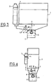
- the second tank 3, in which part of the oil can be diverted, can be separated from the engine 1 (see FIGS. 1 and 3) or adjacent to the engine 1 (see for example FIGS.
- this tank may for example be integrated with the engine block and / or the cylinder head, advantageously at a side face of the engine 1.
- the second reservoir 3 is a constant volume reservoir which is substantially at atmospheric pressure.
- the lubricating device according to the invention comprises connecting means 4 between the first 2 and the second 3 tank allowing oil return by gravity from the second 3 to the first 2 tank.
- the return of oil by gravity is ensured by appropriate relative altitudes of the two tanks 2 and 3 and their connecting means 4.
- the second tank 3 and the junction between the second tank 3 and the connection means 4 are located above the first tank 2,
- the gravity oil return is provided by an overflow system.
- the derived oil arrives in the second tank 3, the volume and thus the oil level increase in this tank 3. When the oil level exceeds a certain predetermined level defined by the overflow system, the excess oil is transferred under the effect of gravity to the first tank 2.
- the second reservoir 3 has a higher oil capacity than the first reservoir 2.
- the first reservoir 2 can contain two liters of oil and the second three four liters. This makes it possible to reduce the volume of the first tank 2 and thus the bulk of the entire engine 1.
- the first tank is arranged to allow a reduction in the height of the entire engine 1. lubrication according to the invention allows a increasing the total volume of oil and thus allows space to drain.
- connection means 4 comprise, in addition to the overflow system, a conduit directly connecting the first 2 to the second 3 tank.
- the embodiments shown in Figures 2 and 4 do not use ducts to connect the second 3 to the first 2 tank.
- the embodiments of FIGS. 2 and 4 use the inside of the engine 1 as connection means 4.
- the overflow system is advantageously arranged so as to create a communication between the second reservoir 3 and the In this way, the oil return is carried out so as to lower the oil, for example, along the inner walls of the engine 1 to the first tank 2.
- the oil return can be provided either via the interior of the engine 1 or via a duct system outside the engine 1 or by a combination of these two modes.
- FIGS. 3 and 4 show variants respectively of the embodiments illustrated in Figures 1 and 2.
- the elements identical to those of the embodiments described above are designated by the same reference numerals and are not described a second time in detail.
- the variants of FIGS. 3 and 4 differ from the embodiments described above solely at the level of the bypass means 8, 9.
- the valve 9 is a valve three-way valve for either drifting oil to the second tank 3 or pouring derived oil directly into the first tank 2.
- Such valves are used in combination with oil pumps requiring a valve
- the discharge valve 10 is generally integrated with the oil pump 5, but it is also possible to mount it separately, for example at the branching means 8, upstream of the valve 9.
- the lubricating device according to the invention described above has a simple and inexpensive structure. More particularly, it allows an optimized regulation of oil exchanges between the first 2 and the second 3 tank ensuring an optimum oil temperature rise for the operation of the engine 1.
- the device according to the invention makes it possible to achieve quickly an optimum temperature for the operation of the engine 1, especially during a cold start, which leads to a reduction in fuel consumption.
- this lubrication device ensures through its oil return system of the second 3 to the first 2 tank an optimized amount of oil in the first tank 2. In this way, the lubricating device according to the invention decreases. considerably the risk of breakdowns due to a lack of oil in the first tank.
- the oil return system according to the invention also allows the use of a single point for filling the first 2 and second 3 tank. When, when filling the second tank 3, the oil level exceeds the predetermined level defined by the overflow system, the excess oil is returned under the effect of gravity in the first tank 2 and thus fills it.
Landscapes
- Engineering & Computer Science (AREA)
- Mechanical Engineering (AREA)
- General Engineering & Computer Science (AREA)
- Lubrication Details And Ventilation Of Internal Combustion Engines (AREA)
- Lubrication Of Internal Combustion Engines (AREA)
Claims (9)
- Vorrichtung zum Schmieren eines Verbrennungsmotors (1) mit einem ersten Ölbehälter (2), einem zweiten Ölbehälter (3), Mitteln (4), die den ersten Behälter (2) mit dem zweiten Behälter (3) verbinden und einen Ölrücklauf vom zweiten Behälter (3) in den ersten Behälter (2) ermöglichen, mit Mitteln (5) zum Ansaugen von Ö1 im ersten Behälter (2), einem ersten Kreis (7), in dem das angesaugte Ö1 im Motor in Umlauf gebracht wird, Mitteln (6) zum Bestimmen der Öltemperatur und mit Mitteln (8, 9) zum selektiven Ableiten abhängig von der Öltemperatur zumindest eines Teils des im ersten Kreis (7) zirkulierenden Öls zum zweiten Behälter (3), dadurch gekennzeichnet, dass der zweite Behälter im Wesentlichen unter Atmosphärendruck steht, dass die Mittel zum selektiven Ableiten einen Ableitungszweig umfassen, der mit dem unteren Ende des zweiten Behälters (3) und vor dem Motor (1) mit dem ersten Kreis (7) verbunden ist, und dadurch dass die Verbindungsmittel (4) ein Überlaufsystem umfassen, das den Rücklauf von Öl durch Schwerkraft vom zweiten Behälter (3) in den ersten Behälter (2) ermöglicht.
- Vorrichtung nach Anspruch 1, dadurch gekennzeichnet, dass die Verbindungsmittel (4) derart angeordnet sind, dass der Rücklauf von Öl aus dem zweiten Behälter (3) in den ersten Behälter (2) zumindest teilweise durch das Innere des Motors (1) erfolgt.
- Vorrichtung nach Anspruch 1 oder 2, dadurch gekennzeichnet, dass die Mittel (8, 9) zum selektiven Ableiten ein Ventil (9) umfassen, das den Durchsatz des abgeleiteten Öls regelt.
- Vorrichtung nach Anspruch 3, dadurch gekennzeichnet, dass das Ventil (9) ein Dreiwegeventil ist, das es ermöglicht, Öl entweder zum zweiten Behälter (3) abzuleiten oder das abgeleitete Öl direkt in den ersten Behälter (2) zurückzuführen.
- Vorrichtung nach einem der Ansprüche 3 oder 4, dadurch gekennzeichnet, dass das Ventil (9) ein Thermoventil ist, in das die Mittel (6) zum Bestimmen der Temperatur integriert sind.
- Vorrichtung nach einem der Ansprüche 1 bis 4, dadurch gekennzeichnet, dass der erste Behälter (2) angrenzend zum Motor, vorzugsweise in dessen unterem Abschnitt (1), angeordnet ist.
- Vorrichtung nach einem der Ansprüche 1 bis 5, dadurch gekennzeichnet, dass der zweite Behälter (3) vom Motor (1) getrennt ist.
- Vorrichtung nach einem der Ansprüche 1 bis 5, dadurch gekennzeichnet, dass der zweite Behälter (3) angrenzend zum Motor (1) angeordnet ist.
- Vorrichtung nach Anspruch 7, dadurch gekennzeichnet, dass der zweite Behälter (3) an einer Seitenfläche des Motors (1) angeordnet ist.
Applications Claiming Priority (2)
| Application Number | Priority Date | Filing Date | Title |
|---|---|---|---|
| FR0450987A FR2870565B1 (fr) | 2004-05-18 | 2004-05-18 | Dispositif de lubrification d'un moteur a combustion interne |
| FR0450987 | 2004-05-18 |
Publications (2)
| Publication Number | Publication Date |
|---|---|
| EP1598532A1 EP1598532A1 (de) | 2005-11-23 |
| EP1598532B1 true EP1598532B1 (de) | 2007-04-11 |
Family
ID=34942305
Family Applications (1)
| Application Number | Title | Priority Date | Filing Date |
|---|---|---|---|
| EP05291063A Expired - Lifetime EP1598532B1 (de) | 2004-05-18 | 2005-05-17 | Schmiervorrichtung für eine Brennkraftmaschine |
Country Status (4)
| Country | Link |
|---|---|
| EP (1) | EP1598532B1 (de) |
| AT (1) | ATE359433T1 (de) |
| DE (1) | DE602005000848T2 (de) |
| FR (1) | FR2870565B1 (de) |
Cited By (2)
| Publication number | Priority date | Publication date | Assignee | Title |
|---|---|---|---|---|
| DE102008021255A1 (de) | 2008-04-29 | 2009-01-22 | Daimler Ag | Schmierstoffspeicherbehälter sowie Schmiertoffkreislauf |
| DE102017114394A1 (de) | 2017-06-28 | 2019-01-03 | Dr. Ing. H.C. F. Porsche Aktiengesellschaft | Verbrennungsmotor, Verfahren zu dessen Herstellung und Kraftfahrzeug |
Families Citing this family (1)
| Publication number | Priority date | Publication date | Assignee | Title |
|---|---|---|---|---|
| FR3004753B1 (fr) * | 2013-04-23 | 2015-05-15 | Peugeot Citroen Automobiles Sa | Procede de montee rapide en temperature de l'huile d'un moteur thermique et carter d'huile |
Family Cites Families (5)
| Publication number | Priority date | Publication date | Assignee | Title |
|---|---|---|---|---|
| US3712420A (en) * | 1971-04-06 | 1973-01-23 | Mack Trucks | Engine lubrication system |
| JPS6166813A (ja) * | 1984-09-10 | 1986-04-05 | Nissan Motor Co Ltd | 内燃機関用オイルパン |
| DE3544724A1 (de) * | 1985-12-18 | 1987-06-19 | Volkswagen Ag | Behaelteranordnung fuer eine betriebsfluessigkeit einer brennkraftmaschine |
| DE4202572C2 (de) * | 1991-02-12 | 2003-04-17 | Volkswagen Ag | Schmier- und/oder Kühlölversorgung für eine Maschine, insbesondere eine Brennkraftmaschine |
| JP4243872B2 (ja) * | 1996-10-31 | 2009-03-25 | ヤマハ発動機株式会社 | 4サイクルエンジン |
-
2004
- 2004-05-18 FR FR0450987A patent/FR2870565B1/fr not_active Expired - Fee Related
-
2005
- 2005-05-17 EP EP05291063A patent/EP1598532B1/de not_active Expired - Lifetime
- 2005-05-17 DE DE602005000848T patent/DE602005000848T2/de not_active Expired - Lifetime
- 2005-05-17 AT AT05291063T patent/ATE359433T1/de not_active IP Right Cessation
Non-Patent Citations (1)
| Title |
|---|
| None * |
Cited By (2)
| Publication number | Priority date | Publication date | Assignee | Title |
|---|---|---|---|---|
| DE102008021255A1 (de) | 2008-04-29 | 2009-01-22 | Daimler Ag | Schmierstoffspeicherbehälter sowie Schmiertoffkreislauf |
| DE102017114394A1 (de) | 2017-06-28 | 2019-01-03 | Dr. Ing. H.C. F. Porsche Aktiengesellschaft | Verbrennungsmotor, Verfahren zu dessen Herstellung und Kraftfahrzeug |
Also Published As
| Publication number | Publication date |
|---|---|
| ATE359433T1 (de) | 2007-05-15 |
| EP1598532A1 (de) | 2005-11-23 |
| FR2870565B1 (fr) | 2006-06-30 |
| FR2870565A1 (fr) | 2005-11-25 |
| DE602005000848T2 (de) | 2007-12-20 |
| DE602005000848D1 (de) | 2007-05-24 |
Similar Documents
| Publication | Publication Date | Title |
|---|---|---|
| EP2801707B1 (de) | Schmierkreislauf eines Turbotriebwerks mit Überlaufventil für Windmilling | |
| FR2723985A1 (fr) | Systeme de pompe a huile | |
| FR2607195A1 (fr) | Dispositif, tubulures et procede pour isoler un compresseur hors service d'un circuit | |
| FR2665731A1 (fr) | Systeme d'alimentation en fluide notamment pour equipement mobile a moteur. | |
| CA2544956A1 (fr) | Clapet a fuite controlee pour gicleur de refroidissement de piston | |
| FR2979004A1 (fr) | Systeme de combustible ayant une unite de controle de combustible et echangeur de chaleur | |
| EP1598532B1 (de) | Schmiervorrichtung für eine Brennkraftmaschine | |
| EP2187016A1 (de) | Kühlmittelkreislauf eines Motors | |
| EP1229218B1 (de) | Automatische Ölstandsteurungvorrichtung für eine Brennkraftmaschine | |
| FR2816354A1 (fr) | Dispositif de lubrification pour moteur a combustion interne | |
| FR3134152A1 (fr) | Un système à compresseurs multiples ayant des soupapes normalement ouvertes dans des raccordements d’équilibrage d’huile | |
| EP4069951B1 (de) | Öldekanter mit einer frischluftkammer | |
| FR2468734A1 (fr) | Installation pour completer automatiquement l'huile de graissage du carter de vilebrequin d'un moteur a combustion interne | |
| FR3035155A1 (fr) | Circuit de distribution de carburant de turbomachine a encombrement reduit | |
| EP0936347B1 (de) | Vorrichtung zür Erhöhung der Temperaturanstiegsgeschwindigkeit des Motoröls | |
| EP3486446A1 (de) | Anordnung von kühlschaltkreisen eines motors | |
| FR3132753A1 (fr) | Un système à compresseurs multiples ayant des conduites d’équilibrage d’huile individuelles | |
| FR3114623A1 (fr) | Compresseur à spirales ayant un système d’injection d’huile | |
| FR2707217A1 (fr) | Réservoir de carburant à poches multiples. | |
| WO2023194126A1 (fr) | Groupe motopropulseur à deux réservoirs de lubrifiant | |
| EP0850791B1 (de) | Heizungssystem für den Fahrgastraum eines Kraftfahrzeuges mit Dieselmotor mit Direkteinspritzung | |
| EP0347272A1 (de) | Einrichtung zum Verbinden von zwei Teilen eines Fluidkreislaufes, von denen eines eine Flüssigkeit enthält | |
| FR3056557A1 (fr) | Systeme d'alimentation en carburant pour un aeronef | |
| EP3315737A1 (de) | Schmiervorrichtung für motor, die einen zusätzlichen behälter umfasst | |
| FR2478769A1 (fr) | Systeme de transmission hydrostatique, notamment pour vehicules automobiles |
Legal Events
| Date | Code | Title | Description |
|---|---|---|---|
| PUAI | Public reference made under article 153(3) epc to a published international application that has entered the european phase |
Free format text: ORIGINAL CODE: 0009012 |
|
| AK | Designated contracting states |
Kind code of ref document: A1 Designated state(s): AT BE BG CH CY CZ DE DK EE ES FI FR GB GR HU IE IS IT LI LT LU MC NL PL PT RO SE SI SK TR |
|
| AX | Request for extension of the european patent |
Extension state: AL BA HR LV MK YU |
|
| 17P | Request for examination filed |
Effective date: 20060512 |
|
| AKX | Designation fees paid |
Designated state(s): AT BE BG CH CY CZ DE DK EE ES FI FR GB GR HU IE IS IT LI LT LU MC NL PL PT RO SE SI SK TR |
|
| GRAP | Despatch of communication of intention to grant a patent |
Free format text: ORIGINAL CODE: EPIDOSNIGR1 |
|
| GRAS | Grant fee paid |
Free format text: ORIGINAL CODE: EPIDOSNIGR3 |
|
| GRAA | (expected) grant |
Free format text: ORIGINAL CODE: 0009210 |
|
| AK | Designated contracting states |
Kind code of ref document: B1 Designated state(s): AT BE BG CH CY CZ DE DK EE ES FI FR GB GR HU IE IS IT LI LT LU MC NL PL PT RO SE SI SK TR |
|
| PG25 | Lapsed in a contracting state [announced via postgrant information from national office to epo] |
Ref country code: FI Free format text: LAPSE BECAUSE OF FAILURE TO SUBMIT A TRANSLATION OF THE DESCRIPTION OR TO PAY THE FEE WITHIN THE PRESCRIBED TIME-LIMIT Effective date: 20070411 Ref country code: SI Free format text: LAPSE BECAUSE OF FAILURE TO SUBMIT A TRANSLATION OF THE DESCRIPTION OR TO PAY THE FEE WITHIN THE PRESCRIBED TIME-LIMIT Effective date: 20070411 |
|
| REG | Reference to a national code |
Ref country code: GB Ref legal event code: FG4D Free format text: NOT ENGLISH |
|
| REG | Reference to a national code |
Ref country code: CH Ref legal event code: EP |
|
| GBT | Gb: translation of ep patent filed (gb section 77(6)(a)/1977) |
Effective date: 20070411 |
|
| REG | Reference to a national code |
Ref country code: IE Ref legal event code: FG4D Free format text: LANGUAGE OF EP DOCUMENT: FRENCH |
|
| REF | Corresponds to: |
Ref document number: 602005000848 Country of ref document: DE Date of ref document: 20070524 Kind code of ref document: P |
|
| PG25 | Lapsed in a contracting state [announced via postgrant information from national office to epo] |
Ref country code: SE Free format text: LAPSE BECAUSE OF FAILURE TO SUBMIT A TRANSLATION OF THE DESCRIPTION OR TO PAY THE FEE WITHIN THE PRESCRIBED TIME-LIMIT Effective date: 20070711 |
|
| PG25 | Lapsed in a contracting state [announced via postgrant information from national office to epo] |
Ref country code: ES Free format text: LAPSE BECAUSE OF FAILURE TO SUBMIT A TRANSLATION OF THE DESCRIPTION OR TO PAY THE FEE WITHIN THE PRESCRIBED TIME-LIMIT Effective date: 20070722 |
|
| PG25 | Lapsed in a contracting state [announced via postgrant information from national office to epo] |
Ref country code: IS Free format text: LAPSE BECAUSE OF FAILURE TO SUBMIT A TRANSLATION OF THE DESCRIPTION OR TO PAY THE FEE WITHIN THE PRESCRIBED TIME-LIMIT Effective date: 20070811 |
|
| PG25 | Lapsed in a contracting state [announced via postgrant information from national office to epo] |
Ref country code: PT Free format text: LAPSE BECAUSE OF FAILURE TO SUBMIT A TRANSLATION OF THE DESCRIPTION OR TO PAY THE FEE WITHIN THE PRESCRIBED TIME-LIMIT Effective date: 20070911 |
|
| NLV1 | Nl: lapsed or annulled due to failure to fulfill the requirements of art. 29p and 29m of the patents act | ||
| PG25 | Lapsed in a contracting state [announced via postgrant information from national office to epo] |
Ref country code: PL Free format text: LAPSE BECAUSE OF FAILURE TO SUBMIT A TRANSLATION OF THE DESCRIPTION OR TO PAY THE FEE WITHIN THE PRESCRIBED TIME-LIMIT Effective date: 20070411 Ref country code: AT Free format text: LAPSE BECAUSE OF FAILURE TO SUBMIT A TRANSLATION OF THE DESCRIPTION OR TO PAY THE FEE WITHIN THE PRESCRIBED TIME-LIMIT Effective date: 20070411 |
|
| REG | Reference to a national code |
Ref country code: IE Ref legal event code: FD4D |
|
| BERE | Be: lapsed |
Owner name: PEUGEOT CITROEN AUTOMOBILES Effective date: 20070531 |
|
| PG25 | Lapsed in a contracting state [announced via postgrant information from national office to epo] |
Ref country code: DK Free format text: LAPSE BECAUSE OF FAILURE TO SUBMIT A TRANSLATION OF THE DESCRIPTION OR TO PAY THE FEE WITHIN THE PRESCRIBED TIME-LIMIT Effective date: 20070411 Ref country code: CZ Free format text: LAPSE BECAUSE OF FAILURE TO SUBMIT A TRANSLATION OF THE DESCRIPTION OR TO PAY THE FEE WITHIN THE PRESCRIBED TIME-LIMIT Effective date: 20070411 Ref country code: IE Free format text: LAPSE BECAUSE OF FAILURE TO SUBMIT A TRANSLATION OF THE DESCRIPTION OR TO PAY THE FEE WITHIN THE PRESCRIBED TIME-LIMIT Effective date: 20070411 Ref country code: MC Free format text: LAPSE BECAUSE OF NON-PAYMENT OF DUE FEES Effective date: 20070531 Ref country code: BG Free format text: LAPSE BECAUSE OF FAILURE TO SUBMIT A TRANSLATION OF THE DESCRIPTION OR TO PAY THE FEE WITHIN THE PRESCRIBED TIME-LIMIT Effective date: 20070711 Ref country code: NL Free format text: LAPSE BECAUSE OF FAILURE TO SUBMIT A TRANSLATION OF THE DESCRIPTION OR TO PAY THE FEE WITHIN THE PRESCRIBED TIME-LIMIT Effective date: 20070411 |
|
| PLBE | No opposition filed within time limit |
Free format text: ORIGINAL CODE: 0009261 |
|
| STAA | Information on the status of an ep patent application or granted ep patent |
Free format text: STATUS: NO OPPOSITION FILED WITHIN TIME LIMIT |
|
| PG25 | Lapsed in a contracting state [announced via postgrant information from national office to epo] |
Ref country code: SK Free format text: LAPSE BECAUSE OF FAILURE TO SUBMIT A TRANSLATION OF THE DESCRIPTION OR TO PAY THE FEE WITHIN THE PRESCRIBED TIME-LIMIT Effective date: 20070411 Ref country code: LT Free format text: LAPSE BECAUSE OF FAILURE TO SUBMIT A TRANSLATION OF THE DESCRIPTION OR TO PAY THE FEE WITHIN THE PRESCRIBED TIME-LIMIT Effective date: 20070411 |
|
| 26N | No opposition filed |
Effective date: 20080114 |
|
| PG25 | Lapsed in a contracting state [announced via postgrant information from national office to epo] |
Ref country code: BE Free format text: LAPSE BECAUSE OF NON-PAYMENT OF DUE FEES Effective date: 20070531 |
|
| REG | Reference to a national code |
Ref country code: GB Ref legal event code: 746 Effective date: 20080329 |
|
| PG25 | Lapsed in a contracting state [announced via postgrant information from national office to epo] |
Ref country code: GR Free format text: LAPSE BECAUSE OF FAILURE TO SUBMIT A TRANSLATION OF THE DESCRIPTION OR TO PAY THE FEE WITHIN THE PRESCRIBED TIME-LIMIT Effective date: 20070712 Ref country code: IT Free format text: LAPSE BECAUSE OF FAILURE TO SUBMIT A TRANSLATION OF THE DESCRIPTION OR TO PAY THE FEE WITHIN THE PRESCRIBED TIME-LIMIT Effective date: 20070411 |
|
| PG25 | Lapsed in a contracting state [announced via postgrant information from national office to epo] |
Ref country code: RO Free format text: LAPSE BECAUSE OF FAILURE TO SUBMIT A TRANSLATION OF THE DESCRIPTION OR TO PAY THE FEE WITHIN THE PRESCRIBED TIME-LIMIT Effective date: 20070411 |
|
| PG25 | Lapsed in a contracting state [announced via postgrant information from national office to epo] |
Ref country code: EE Free format text: LAPSE BECAUSE OF FAILURE TO SUBMIT A TRANSLATION OF THE DESCRIPTION OR TO PAY THE FEE WITHIN THE PRESCRIBED TIME-LIMIT Effective date: 20070411 |
|
| PG25 | Lapsed in a contracting state [announced via postgrant information from national office to epo] |
Ref country code: CY Free format text: LAPSE BECAUSE OF FAILURE TO SUBMIT A TRANSLATION OF THE DESCRIPTION OR TO PAY THE FEE WITHIN THE PRESCRIBED TIME-LIMIT Effective date: 20070411 |
|
| PG25 | Lapsed in a contracting state [announced via postgrant information from national office to epo] |
Ref country code: LU Free format text: LAPSE BECAUSE OF NON-PAYMENT OF DUE FEES Effective date: 20070517 |
|
| PG25 | Lapsed in a contracting state [announced via postgrant information from national office to epo] |
Ref country code: TR Free format text: LAPSE BECAUSE OF FAILURE TO SUBMIT A TRANSLATION OF THE DESCRIPTION OR TO PAY THE FEE WITHIN THE PRESCRIBED TIME-LIMIT Effective date: 20070411 Ref country code: HU Free format text: LAPSE BECAUSE OF FAILURE TO SUBMIT A TRANSLATION OF THE DESCRIPTION OR TO PAY THE FEE WITHIN THE PRESCRIBED TIME-LIMIT Effective date: 20071012 |
|
| REG | Reference to a national code |
Ref country code: CH Ref legal event code: PL |
|
| PG25 | Lapsed in a contracting state [announced via postgrant information from national office to epo] |
Ref country code: CH Free format text: LAPSE BECAUSE OF NON-PAYMENT OF DUE FEES Effective date: 20090531 Ref country code: LI Free format text: LAPSE BECAUSE OF NON-PAYMENT OF DUE FEES Effective date: 20090531 |
|
| PGFP | Annual fee paid to national office [announced via postgrant information from national office to epo] |
Ref country code: DE Payment date: 20120423 Year of fee payment: 8 |
|
| PGFP | Annual fee paid to national office [announced via postgrant information from national office to epo] |
Ref country code: GB Payment date: 20120423 Year of fee payment: 8 Ref country code: FR Payment date: 20120625 Year of fee payment: 8 |
|
| GBPC | Gb: european patent ceased through non-payment of renewal fee |
Effective date: 20130517 |
|
| PG25 | Lapsed in a contracting state [announced via postgrant information from national office to epo] |
Ref country code: DE Free format text: LAPSE BECAUSE OF NON-PAYMENT OF DUE FEES Effective date: 20131203 |
|
| REG | Reference to a national code |
Ref country code: DE Ref legal event code: R119 Ref document number: 602005000848 Country of ref document: DE Effective date: 20131203 |
|
| REG | Reference to a national code |
Ref country code: FR Ref legal event code: ST Effective date: 20140131 |
|
| PG25 | Lapsed in a contracting state [announced via postgrant information from national office to epo] |
Ref country code: GB Free format text: LAPSE BECAUSE OF NON-PAYMENT OF DUE FEES Effective date: 20130517 |
|
| PG25 | Lapsed in a contracting state [announced via postgrant information from national office to epo] |
Ref country code: FR Free format text: LAPSE BECAUSE OF NON-PAYMENT OF DUE FEES Effective date: 20130531 |