EP1598522B1 - Composants d'une turbine à vapeur, procédé pour refroidir une turbine à vapeur et leur utilisation - Google Patents
Composants d'une turbine à vapeur, procédé pour refroidir une turbine à vapeur et leur utilisation Download PDFInfo
- Publication number
- EP1598522B1 EP1598522B1 EP04012135A EP04012135A EP1598522B1 EP 1598522 B1 EP1598522 B1 EP 1598522B1 EP 04012135 A EP04012135 A EP 04012135A EP 04012135 A EP04012135 A EP 04012135A EP 1598522 B1 EP1598522 B1 EP 1598522B1
- Authority
- EP
- European Patent Office
- Prior art keywords
- cooling
- steam turbine
- cooling medium
- restricting
- flow
- Prior art date
- Legal status (The legal status is an assumption and is not a legal conclusion. Google has not performed a legal analysis and makes no representation as to the accuracy of the status listed.)
- Expired - Lifetime
Links
- 238000001816 cooling Methods 0.000 title claims description 196
- 238000000034 method Methods 0.000 title claims description 13
- 239000002826 coolant Substances 0.000 claims description 163
- 230000008859 change Effects 0.000 claims description 18
- 239000012530 fluid Substances 0.000 claims description 13
- 239000007788 liquid Substances 0.000 claims description 11
- 238000011144 upstream manufacturing Methods 0.000 claims description 6
- 230000000694 effects Effects 0.000 description 15
- 230000009467 reduction Effects 0.000 description 14
- 238000011161 development Methods 0.000 description 8
- 230000018109 developmental process Effects 0.000 description 8
- 239000000463 material Substances 0.000 description 8
- 238000001704 evaporation Methods 0.000 description 6
- 230000008020 evaporation Effects 0.000 description 6
- 230000008901 benefit Effects 0.000 description 5
- 238000005253 cladding Methods 0.000 description 5
- 238000010586 diagram Methods 0.000 description 5
- 239000000919 ceramic Substances 0.000 description 4
- 238000009834 vaporization Methods 0.000 description 4
- 230000008016 vaporization Effects 0.000 description 4
- 230000003247 decreasing effect Effects 0.000 description 3
- 230000001419 dependent effect Effects 0.000 description 3
- 230000017525 heat dissipation Effects 0.000 description 3
- 239000011148 porous material Substances 0.000 description 3
- PXHVJJICTQNCMI-UHFFFAOYSA-N Nickel Chemical compound [Ni] PXHVJJICTQNCMI-UHFFFAOYSA-N 0.000 description 2
- 229910000831 Steel Inorganic materials 0.000 description 2
- 238000005553 drilling Methods 0.000 description 2
- 230000001747 exhibiting effect Effects 0.000 description 2
- 239000002184 metal Substances 0.000 description 2
- 229910052751 metal Inorganic materials 0.000 description 2
- 230000004048 modification Effects 0.000 description 2
- 238000012986 modification Methods 0.000 description 2
- 230000002829 reductive effect Effects 0.000 description 2
- 239000000243 solution Substances 0.000 description 2
- 239000010959 steel Substances 0.000 description 2
- 230000035882 stress Effects 0.000 description 2
- 238000010521 absorption reaction Methods 0.000 description 1
- 238000007792 addition Methods 0.000 description 1
- 230000002411 adverse Effects 0.000 description 1
- 239000000956 alloy Substances 0.000 description 1
- 229910045601 alloy Inorganic materials 0.000 description 1
- 238000010276 construction Methods 0.000 description 1
- 238000005516 engineering process Methods 0.000 description 1
- 239000002803 fossil fuel Substances 0.000 description 1
- 230000006872 improvement Effects 0.000 description 1
- 230000004941 influx Effects 0.000 description 1
- 238000002347 injection Methods 0.000 description 1
- 239000007924 injection Substances 0.000 description 1
- 230000000670 limiting effect Effects 0.000 description 1
- 238000004519 manufacturing process Methods 0.000 description 1
- 229910052759 nickel Inorganic materials 0.000 description 1
- 230000036961 partial effect Effects 0.000 description 1
- 238000010248 power generation Methods 0.000 description 1
- 238000007493 shaping process Methods 0.000 description 1
- 239000011343 solid material Substances 0.000 description 1
- 230000008646 thermal stress Effects 0.000 description 1
- 230000007704 transition Effects 0.000 description 1
- 238000010792 warming Methods 0.000 description 1
- XLYOFNOQVPJJNP-UHFFFAOYSA-N water Substances O XLYOFNOQVPJJNP-UHFFFAOYSA-N 0.000 description 1
- 230000003313 weakening effect Effects 0.000 description 1
Images



Classifications
-
- F—MECHANICAL ENGINEERING; LIGHTING; HEATING; WEAPONS; BLASTING
- F02—COMBUSTION ENGINES; HOT-GAS OR COMBUSTION-PRODUCT ENGINE PLANTS
- F02C—GAS-TURBINE PLANTS; AIR INTAKES FOR JET-PROPULSION PLANTS; CONTROLLING FUEL SUPPLY IN AIR-BREATHING JET-PROPULSION PLANTS
- F02C7/00—Features, components parts, details or accessories, not provided for in, or of interest apart form groups F02C1/00 - F02C6/00; Air intakes for jet-propulsion plants
- F02C7/12—Cooling of plants
- F02C7/16—Cooling of plants characterised by cooling medium
-
- F—MECHANICAL ENGINEERING; LIGHTING; HEATING; WEAPONS; BLASTING
- F01—MACHINES OR ENGINES IN GENERAL; ENGINE PLANTS IN GENERAL; STEAM ENGINES
- F01D—NON-POSITIVE DISPLACEMENT MACHINES OR ENGINES, e.g. STEAM TURBINES
- F01D5/00—Blades; Blade-carrying members; Heating, heat-insulating, cooling or antivibration means on the blades or the members
- F01D5/12—Blades
- F01D5/14—Form or construction
- F01D5/18—Hollow blades, i.e. blades with cooling or heating channels or cavities; Heating, heat-insulating or cooling means on blades
-
- F—MECHANICAL ENGINEERING; LIGHTING; HEATING; WEAPONS; BLASTING
- F05—INDEXING SCHEMES RELATING TO ENGINES OR PUMPS IN VARIOUS SUBCLASSES OF CLASSES F01-F04
- F05D—INDEXING SCHEME FOR ASPECTS RELATING TO NON-POSITIVE-DISPLACEMENT MACHINES OR ENGINES, GAS-TURBINES OR JET-PROPULSION PLANTS
- F05D2260/00—Function
- F05D2260/20—Heat transfer, e.g. cooling
Definitions
- the invention relates to a steam turbine component, which has a surface bounding a flow channel, wherein the flow channel is provided for receiving a main flow of a fluid working medium, and having a on its surface an opening to the flow channel exhibiting cooling system for receiving a cooling medium flow with a cooling medium pressure and a Has cooling medium temperature.
- the invention further relates to a method for cooling a steam turbine, wherein the flow channel is acted upon by a main flow of a fluid working medium, and the cooling system with a cooling medium flow, with a cooling medium pressure and a cooling medium temperature, is applied.
- the invention also relates to a use.
- a steam turbine is understood to mean any turbine or sub-turbine through which a working medium in the form of steam flows.
- gas turbines are traversed with gas and / or air as the working medium, which, however, is subject to completely different temperature and pressure conditions than the steam in a steam turbine.
- gas turbines has steam turbines z.
- An open cooling system with a cooling system that is open to the flow channel can also be implemented in the case of gas turbines without the supply of cooling medium to the outside of the turbine.
- an external supply should be provided. The state of the art regarding gas turbines can already be so not be used for the assessment of the present application.
- a steam turbine component with a surface bounding a flow channel may be in the form of a blade of a rotor or of a housing, in particular of an input region.
- a steam turbine typically comprises a rotor-mounted rotatably mounted rotor disposed within a housing.
- the rotor When flowing through the interior of the flow channel formed by the housing shell with heated and pressurized steam, the rotor is rotated by the vanes through the steam.
- the blades of the rotor are also referred to as blades.
- usually stationary guide vanes are suspended on the housing jacket, which engage along an axial extent of the body in the interspaces of the rotor blades.
- a vane is typically held at a first location along an interior of the steam turbine casing. In this case, it is usually part of a stator blade row, which comprises a number of guide vanes, which are arranged along an inner circumference on the inside of the steam turbine housing.
- Each vane has its blade radially inward.
- a row of vanes at said first location along the axial extent is also referred to as a vane grille or crown.
- a number of rows of blades are connected in series. Accordingly, at a second location along the axial extent behind the first location, a further second blade is held along the inside of the steam turbine housing.
- a pair of a vane row and a blade row is also referred to as a vane stage.
- the housing jacket of such a steam turbine can be formed from a number of housing segments. Under the housing shell
- the steam turbine is to be understood in particular as the stationary housing component of a steam turbine or a partial turbine, which along the longitudinal direction of the steam turbine has an interior space in the form of a flow channel which is provided for the flow through with the working medium in the form of steam.
- this can be an inner casing and / or a guide vane carrier.
- it may also be provided a turbine housing, which has no inner housing or no guide vane.
- a blade cooling is out of the WO 97/08431 known.
- the invention begins, whose object is to provide a steam turbine component, a method and a use, according to which a steam turbine is cooled particularly effectively, even in the high temperature range.
- the invention is based on the finding that an arrangement of a throttle means at a near-surface throttle point causes a temperature reduction of the cooling medium that is effective in comparison to the rest of the coolant temperature directly at the throttle point and toward the surface.
- the invention is based on the consideration that with an active cooling cooling by a cooling medium with a predetermined temperature, for. B. above 500 ° C, for example at 540 ° C or more, takes place, wherein a cooling medium temperature is suitably below the temperature of the working medium, in particular at locations of the cooling medium flow respectively corresponding to locations of the main flow.
- the cooling effect of the cooling medium is usually limited by the fact that only the temperature difference between the cooling medium temperature of the cooling medium and the flow temperature of the working medium for cooling the component is effective. It is based on the assumption that a component temperature is significantly influenced by the temperature of the working medium in the absence of cooling or practically is approximately equal to the temperature of the working medium.
- the cooling system is integrated in the component.
- the cooling system for. B. be formed in the form of channels and / or cavities in a body of the component itself.
- the cooling system can also be formed by shielding plates or elements and a body of the component by the shielding plates are spaced from the body and a cooling system in the form of formed by the spacing channels and cavities is formed.
- the arrangement of the throttle means at a near-surface throttle point in particular achieves a throttling of the cooling medium directly at the throttle point and up to the surface of the component, so that a further temperature reduction of the cooling medium temperature is effected in addition to the abovementioned usual temperature difference is thus and as a result a larger compared to the prior art temperature difference for cooling the working medium caused by the cooling medium.
- the dissipated heat flow from the working medium is determined by a mass flow of the cooling medium and said by the present concept increased effective temperature difference between the cooling medium and working fluid on the surface of the steam turbine component and in particular at the opening to the flow channel.
- the throttle point is disposed within a wall of the steam turbine component offset relative to a central surface of the wall toward the surface. This ensures that an appropriate cooling takes place where the cooling demand is particularly high, namely as close as possible at the flow channel, which is provided for receiving the hot working medium.
- the concept proposed here offers the additional advantage that a temperature reduction of the cooling medium is achieved directly at the throttle point and up to the surface of the steam turbine component.
- the maximum cooling effect is thus achieved specifically on the surface to be cooled or is specifically directed to the surface to be cooled.
- a warming of the cooling medium is reduced when flowing through cooling channels to the throttle point compared to previously known solutions at the same temperature difference available for cooling.
- the cooling effect can be maximized by causing a phase change from a liquid state upstream of the throttle point to a vapor state downstream of the throttle point in at least part of the cooling medium. That is, when passing through the throttle means, a phase transition takes place, so that in the present case can be spoken of evaporative cooling.
- the enthalpy of evaporation for heat removal from the working medium also comes into play.
- the amount of heat that can be dissipated is several times greater than the heat quantity that can be achieved by pure throttling.
- any surface of a steam turbine component bordering the flow channel and thus a surface of a steam turbine component delimiting the flow channel can advantageously be cooled in accordance with the new concept.
- suitable components to be cooled are a steam turbine blade and, moreover, any component which carries a number of blade stages having a plurality of blades and arranged longitudinally one behind the other, each extending into the flow channel. This is in particular a steam turbine rotor or a steam turbine housing.
- the cooling system can be expediently designed in the context of advantageous developments that it is arranged as close as possible to the flow channel.
- the main cooling channel extends over an extension of at least one blade row.
- branch cooling channel expediently has a ring channel surrounding a row of blades.
- the branch cooling channel has one or more outgoing from an annular channel blade channels, which lead into at least one blade stage. That is, it is expedient to provide a number of blade channels, which preferably lead into all blades of a blade stage. Preferably, at least one blade channel is provided per blade.
- a branch cooling channel is preferably transverse to the longitudinal direction, d. H. in a radial direction of the component. That is, a branch cooling channel preferably extends transversely to a main flow of the fluid working medium. The same applies to a blade channel.
- the inflow region of a steam turbine can be advantageously cooled in this way. That is to say, the cooling system described above is preferably arranged in the inflow region of a steam turbine, that is to say in the inflow region of a housing and / or a rotor or in the first vane stages, which lie closest to an inflow region.
- the throttle means can be arranged and / or configured in a particularly advantageous manner.
- the throttle means is arranged at a near-surface throttle point in a main cooling channel.
- the main cooling channel can be guided to the surface to allow a near-surface arrangement of the throttle point.
- the throttle means can be arranged particularly advantageous at a near-surface throttle point in a branch cooling channel.
- the above-mentioned graduation of a cooling system in the main cooling channel and branch cooling channel leaves realize both in terms of a turbine blade and in terms of a rotor or a housing.
- the throttle means is particularly advantageously arranged at a near-surface throttle point in an annular channel.
- the throttling means can in principle be constructed in different ways to fulfill its function carried out according to the proposed concept.
- the throttle means have a geometrically fixed shape. It has been shown that due to the geometrically fixed default after throttling the main, branch, ring and / or blade cooling channel, a cooling medium pressure and a cooling medium temperature can be adjusted specifically. Usually, steam turbines are operated within certain pressure and temperature parameters, in particular the above-mentioned high-temperature parameters. Thus, a flow pressure and a flow temperature of the working medium are usually known and predetermined along the longitudinal direction of the flow channel.
- the geometric shape of the throttle means at the one or more throttle points along the longitudinal direction of the flow channel is thus designed so that the cooling medium has a cooling effect which is particularly advantageous for cooling.
- the cooling effect is mainly characterized by a differential temperature of the cooling medium to the working medium and in particular to be cooled component and characterized by a cooling mass flow.
- the throttling of the cooling medium can be a cooling of the cooling medium in the context of a temperature drop of preferably at least 10 K to 100 K.
- a cooling of the cooling medium can be between 20 K and 75 K.
- the temperature reduction can vary along the longitudinal direction.
- the throttle means is formed in the form of the opening of the cooling system.
- the opening can be formed particularly easily in the form of a targeted geometric constriction and thus as a targeted local cross-sectional constriction of the clear width of the cooling system. That is, the cross-sectional constriction may occur directly on the surface of the steam turbine component.
- the throttle means may be arranged in a region in front of the surface in a cooling channel.
- the shape of a waist of the cooling channel and / or the opening of the cooling system proves to be advantageous.
- the throttle means may be formed in the form of a surface enlarging, semipermeable plug in a cooling channel and / or the opening of the cooling system.
- throttling is particularly suitable ceramics or a metal or steel structure, for.
- wire mesh or the like as a particularly useful plug material.
- the throttle means may be formed in the form of a surface enlarging acting, semipermeable cladding on the surface of the component in the region of the opening to the flow channel.
- the panel may expediently in the form of a sheet with a narrow mesh size and / or underlying porous material, eg. B. in the form of a ceramic or in a the forms explained above, be formed.
- the sheet may be provided with holes or gaps and be formed mesh-like.
- the cladding particularly expediently also covers the cooling channels of the cooling system which open into the surface of the component to be cooled. In this case, the cooling medium enters from the cooling system via or through the lining into the flow channel carrying the working medium.
- the present invention further relates to a steam turbine, in particular to a high-temperature steam turbine with a steam turbine component, as described above.
- a steam turbine in particular to a high-temperature steam turbine with a steam turbine component, as described above.
- this can be defined, in particular, by applying a working medium in accordance with the pressure and temperature parameters explained in the "Neft" article.
- the object is achieved by the invention with a method of the type mentioned, in which according to the invention with at least one flow resistance in the form of a throttle means at a throttle point in the cooling system, in the flow direction of the cooling medium, a pressure drop of the cooling medium pressure is set via the throttle point, and at the throttle point, a temperature coverage of the cooling medium temperature is effected.
- a cooling method in this form enables efficient cooling as described above, particularly of a high-temperature steam turbine.
- the effect of the throttle means is particularly effective when it is placed at a near-surface throttle.
- a phase change is effected from a liquid state upstream of the orifice to a vaporous state downstream of the orifice.
- the enthalpy of evaporation can also be used to cool the working medium through the cooling medium.
- the method provides that the cooling medium pressure in the cooling system with at least one further flow resistance is maintained above a flow pressure of the main flow.
- the further flow resistance is to be distinguished here from the throttle means and is designed due to its other function in contrast to the throttle means.
- the further flow resistance can be realized in the form of a flexible resistance device which has no geometrically predetermined shape.
- a flow resistance valve designed in accordance with the cooling medium flow may be used, the opening and passage behavior of which takes into account the flow pressure of the working medium and the cooling medium pressure of the cooling medium flow.
- the object is achieved by the invention by using a throttle means at a near-surface throttle as flow resistance in the cooling system of a steam turbine according to the above-described forms to set a pressure drop of the cooling medium pressure via the throttle point during operation of the steam turbine in the flow direction of the cooling medium such that a temperature reduction of the cooling medium temperature is effected at the throttle point.
- a phase change from a liquid state before the throttle point is effected to a vapor state behind the throttle point.
- the steam turbine 10 has a rotor 1 with a number of rotor blades or blades mounted thereon, which are arranged in so-called blade rows 3 one behind the other.
- the blade rows 3 are rotatable in a housing 5, which has a number of rows of stator blades 7 and thereby extends along an axial extension along an axis, ie in the longitudinal direction 9.
- the rotatable blade rows 3 engage like fingers in spaces between the stationary vane rows. 7
- the steam turbine housing 5 is designed as a particularly preferred embodiment of a steam turbine component according to the concept of the invention.
- the housing 5 could also be designed as an inner housing or as a guide blade carrier and / or in the manner of a segmented construction be formed by a number of housing segments.
- the housing 5 has an inner wall 11 and an outer wall 13. With the inner wall, the housing 5 defines a flow channel 15, which is provided for receiving a main flow 17 of a fluid working medium.
- the working medium has along the longitudinal direction to a changing flow pressure and a changing flow temperature.
- the housing 5 has a cooling system 19, which is open to the flow channel 15 and integrated in the housing 5, for receiving a cooling medium flow having a cooling medium pressure and a cooling medium temperature.
- the cooling medium pressure is characterized by the decreasing pressures p 1 > p 2 > p 3 in its height.
- the flow pressure in the example explained here is characterized by the decreasing pressures P 1 > P 2 > P 3 in its sequence.
- decreasing pressures of the cooling medium and the main flow are not necessarily present in any operating condition and the pressures may be different in other examples.
- the pressures of the cooling medium could in a worse example in the limit case even as p 1 ⁇ p 2 ⁇ p 3 behave.
- the cooling system 19 shown in FIG. 1 has a main channel 23 which extends in the longitudinal direction 9 over all blade rows 3, 7.
- the cooling system also has per guide vane row 7 a branch cooling channel 25, which branches off from the main cooling channel 23 and is open to the flow channel 15.
- the housing or one or more blades on its / its surface / n an opening to the flow channel.
- the cooling system 19 has at least one in relation to the 3 to 7 explained in detail flow resistance in the form of a throttle means at a near-surface throttle point, which sets in the flow direction of the cooling medium, a pressure drop of the cooling medium pressure via the throttle point such that at the throttle point, a temperature drop the cooling medium temperature is effected.
- a phase change from a liquid state upstream of the throttle point to a vaporous state downstream of the throttle point is effected.
- FIG. 2 shows a further particularly preferred embodiment of a high-temperature steam turbine 20 which is acted upon with steam as the working medium at a pressure above 250 bar and a temperature above 540 ° C or in modifications according to parameters in the "Neft" article.
- FIG 2 features of the same function with the same reference numerals as in FIG 1 are named, even if they are designed differently in detail in the embodiment of Figure 2 in contrast to the embodiment of Figure 1.
- This relates in particular to the cooling system 19 with the main cooling channel 23 and the branch cooling channels 25.
- the cooling system 19 is integrated in a rotor 31 as a special embodiment of a steam turbine component and performs essentially the same functions as the cooling system explained with reference to FIG. Accordingly, the conditions explained for the pressures p 1 > p 2 > p 3 and P 1 > P 2 > P 3 also apply in this embodiment, even if these pressures now occur at different locations.
- each pressure p is a corresponding temperature t and each pressure P is associated with a corresponding temperature T. Also for the temperatures t 1 > t 2 > t 3 and T 1 > T 2 > T 3 apply in this example.
- the rotor 31 delimits the flow channel 15 with its outer wall 33.
- the blade rows 35 in contrast to the rotor blade rows 3 of FIG. 1, are designed with the cooling system 19 and, in particular, with the branch cooling channels 25.
- the guide blade rows 27 of the housing 29 have no cooling channels.
- the steam turbine housing is designed as a particularly preferred embodiment of a steam turbine component and in the embodiment of Figure 2, only the steam turbine rotor is designed as a particularly preferred embodiment of the steam turbine component, yet can not in another here shown embodiment of a high-temperature steam turbine, a steam turbine housing and a steam turbine rotor alike a cooling system 19 as shown in each case in Figures 1 and 2.
- a correspondingly designed cooling system can also be mounted in a turbine blade, as shown for example in FIG. This may be a vane of the vane row 7 or a blade of the blade row 3.
- a pressure drop of the cooling medium pressure p is set via the throttle point in the flow direction of the cooling medium and a temperature reduction of the cooling medium temperature at the throttle point p, as shown by way of example in the h / s diagram of FIG.
- the cooling is carried out by a cooling medium with, for example, at 500 ° C predetermined temperature t, which is below the respective temperature T of the working medium in the flow channel 15.
- the cooling effect is limited to the temperature difference between the cooling medium temperature t and the flow temperature T.
- the heat absorption of the cooling medium is given by the isobaric change of state from the numeral 2 to the numeral 3 and characterized by a temperature difference according to the illustrated example in the amount of 75 K.
- the cooling medium temperature of the cooling medium can be varied as such, of course.
- this proves to be a comparatively more complex and slower measure.
- the cooling effect could also be influenced in a targeted manner depending on the cooling requirements, which among other things are load-dependent in a steam turbine.
- a change of state is shown at a second cooling location, which lies downstream of the cooling location, for which the examples explained above are shown.
- a change of state at the second cooling point leads to the state with the number 3 I - compared to the above-mentioned state with the number 3.
- Characteristic of the second cooling point is that with her the expansion of the working medium and the cooling medium has progressed further. At the second cooling point so there is a lower pressure. According to the state of the art, one would have to start with a change of state from the number 2 V to the number 3 I and with a temperature difference of 35 K, z. B. in a cooling medium of 500 ° C, content.
- the dissipated heat flow can of course also be determined by the mass flow of the cooling medium.
- the effective differential temperature is decisive, which is advantageously increased according to the new concept presented here in that an additional temperature reduction of the cooling medium temperature t is effected at the throttle point.
- FIG 4 shows a steam turbine blade 40 as a preferred embodiment of a steam turbine component, in which a cooling system 19 has a main cooling channel 23 which extends in the longitudinal direction 9 of the steam turbine blade 40.
- the cooling system 19 also has a branch cooling channel 25, which branches off from the main cooling channel 23 and is open towards the flow channel 15 via an opening 46.
- the flow channel 15 is provided for receiving a main flow 17 of a fluid working medium.
- the cooling system 19 serves to accommodate a cooling medium flow 21, the cooling medium flow 21 being characterized by a cooling medium pressure p and a cooling medium temperature t as the cooling medium parameter.
- Each of the branch cooling channels 25 has a flow resistance in the form of a throttle means at a near-surface throttle point 41 on.
- the throttle point 41 within a wall 43 of the steam turbine blade 40 relative to a central surface of the wall, in the present case in the form of the longitudinal direction 9, arranged offset to the surface 45 toward.
- the branch cooling channel 25 to a throttle means which is formed in this case in different ways.
- the throttle means in the form of a sidecut 47 of the cooling channel 25 is formed.
- the throttling means is formed in the form of a surface enlarging, semipermeable plug 49.
- the waisting 47 is thus a cross-sectional constriction of the branch cooling channel 25 in the form of a targeted geometric narrowing of the clear width of the branch cooling channel 25.
- the surface enlarging, semipermeable plug 49 is in the present case a porous material, which advantageously a ceramic or a metal or steel structure, for. As a wire mesh or the like may be.
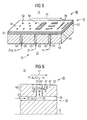
- a cooling system 19 has a main cooling channel 23 and branch cooling channels 25 for receiving a cooling medium 21, wherein the cooling medium is characterized by a cooling medium temperature t and a cooling medium pressure p.
- the in FIG. 5 represented part could equally represent an input-side rotor part.
- a throttle means in the form of a devisvidver Anlagenrnd acting, semipermeable cladding on the surface 53 of the housing part 50 in the region of an opening 55 of the branch cooling channel 25 is formed.
- the lining 51 is placed on the flow channel 15 defining surface 53, wherein the flow channel 15 is provided for receiving a main flow 17 of a fluid working medium.
- the cladding is present in two layers.
- a first layer 57 is formed with a porous material, here in the form of a ceramic.
- the second layer 59 is formed in the form of a cover plate.
- the cover plate has for the passage of cooling medium here exemplified openings.
- the openings may be formed as shown in the form of holes 52, a network structure 54 or in the form of columns 56 in any arrangement and combination.
- Dimensions, shape and detail of the first layer 57 and the second layer 59 can be carried out depending on the local requirement of the cooling medium parameters p, t and the working medium parameters P, T, to cause at the throttle point 41, a temperature drop of the cooling medium temperature t such that at At least a portion of the cooling medium 21 is a phase change from a liquid state before the throttle body 41 is effected to a vapor state behind the throttle 41.
- FIG. 6 shows in detail a throttle means shown in FIG. 4 in the form of a sidecut 47 of a branch cooling channel 25.
- the illustrated particularly preferred embodiment of the steam turbine component 60 has a wall 61 in whose near-surface region the throttle point 41 is arranged. That is, the throttle 41 is relatively within the wall 61 arranged offset to a central surface 8 of the wall 61 to the surface 63 out.
- the throttle point 41 is arranged at a distance of not more than 50% of the component thickness to the surface 63. For a frequently occurring case of component thickness, such a distance can be up to 100 mm.
- the throttle body 41 is arranged at a distance of not more than 25% of the component thickness to the surface 63. For a common case, the distance may be more than 10 mm to 20 mm.
- the cooling medium 21 has in front of the throttle body 41 a cooling medium (- réelle) pressure p i and a cooling medium (- réelle) temperature t i and behind the choke point 41 a cooling medium (-Aus) pressure p a and a cooling medium (-Out) temperature t a on.
- the area near the surface 66 is to be understood as an area between the throttle point 41 of the branch cooling channel 25 and the opening 67 on the surface 63.
- the recorded enthalpy of evaporation is used for increased heat dissipation.
- the flow channel 15 is acted upon by a main flow 17 of a fluid working medium.
- the cooling system 19 is acted upon by a cooling medium flow 21 having a cooling medium pressure p and a cooling medium temperature t.
- a pressure drop Ap of the cooling medium pressure p i -p a over the orifice 41 is set with at least one flow resistance in the form of a throttle means.
- a temperature reduction .DELTA.t the cooling medium temperature t is effected at the throttle point 41, wherein in the present example of the method for at least a portion of the cooling medium 21, a phase change from a liquid state p i , t i before the throttle body 41 to a vapor state p a , t a is effected behind the throttle 41.
- FIG. 7 again shows in detail a throttle means, as could be used, for example, in FIG.
- the throttling means of FIG. 7 is presently in the form of a constriction 48 of a branch cooling channel 25, wherein in the embodiment shown here the constriction continues immediately adjacent to a main cooling channel 23 into the branch cooling channel 25.
- the further course of the branch cooling channel 25 toward the flow channel 15 results in the form of a widening 42 of the branch cooling channel 25.
- the operating principle of such a throttling means of FIG. 7 essentially corresponds to the active principle explained in connection with FIG.
- the other essential features provided with the same function of FIG. 7 have been given the same reference numerals in comparison to FIG.
- the advantage of the throttling means explained here in the form of a constriction 48 is, in addition to the advantages explained in connection with FIG. 6, above all that cooling in the present case can already take place in the region of a branch between main cooling channel 23 and branch cooling channel 25.
- This can, as shown in FIG. 7, already be in the region of a region near the surface 66, in particular when the main cooling channel 23 is arranged relatively close to the surface.
- the constriction 48 shown could also lie outside a region close to the surface, so that cooling, in particular of the solid material of a steam turbine component 70, takes place if required.
- the cooling effect can continue up to the surface 63.
- the branch cooling channel 25 in the form shown here with a constriction 48 and an extension 42 can namely be carried out in a particularly advantageous manner by attaching two consecutively executed drilling operations with different bore diameter.
- an opening 67 is initially produced in that a hole in the wall 61 is first made with a small diameter d. At the same point the opening 67 is then set a further hole. The further bore, however, takes place with a larger diameter D and the further bore is not continued until the main cooling channel 23. Rather, the drilling depth L is selected for a purposeful throttling of the coolant in the region of the constriction 48 as needed and strength of the 61.
- FIG. 8 shows a further part of a particularly preferred embodiment 80 of a steam turbine component, in which a cooling system 19 a main cooling channel, not shown 23 and a branch cooling channel 25 having an opening 71 on the surface 73 of the embodiment 80.
- a throttle means at the near-surface throttle point 75 in the branch cooling channel 25 in the wall 76 is arranged.
- the throttle means is presently formed in the form of the opening 71 of the cooling system 19 on the surface 73.
- the opening 71 of the branch cooling channel 25 has a sidecut 77.
- the opening 71 is further provided with a semi-permeable plug 79 which is inserted into the opening 71 of the branch cooling channel 25 and fixed with locking 78.
- the plug 79 is presently formed with a close-meshed wire mesh.
- a cooling medium 21 z. B. from a cooling medium internal temperature t i in the amount of about 500 ° C to a cooling medium outside temperature t a in the amount of 475 ° C are cooled so that a temperature drop ⁇ t in the amount of 25 K results, in addition to the temperature difference between the cooling medium temperature t i and working medium temperature T for cooling the working medium in the main flow 17 is available.
- a steam turbine component 10, 20, 40, 50, 60, 70, 80 has a flow channel 15 bounding surface 45, 53, 63, 73, wherein the flow channel 15 is provided for receiving a main flow 17 of a fluid working medium is.
- the steam turbine component 10, 20, 40, 50, 60, 70, 80 has on its surface 45, 53, 63, 73 an opening 46, 55, 67, 71 to the flow channel 15 exhibiting, in the component 10, 20, 40, 50, 60, 70, 80 integrated cooling system 19 for receiving a cooling medium flow 21 with a cooling medium pressure p and a cooling medium temperature t.
- the cooling system 19 at least one flow resistance in the form of a throttle means at a near-surface throttle point 41, 75.
- a phase change from a liquid state p i , t i before the throttle point 41, 75 to a vapor state p a , t a behind the throttle point 41, 75 causes.
Landscapes
- Engineering & Computer Science (AREA)
- Chemical & Material Sciences (AREA)
- Combustion & Propulsion (AREA)
- Mechanical Engineering (AREA)
- General Engineering & Computer Science (AREA)
- Turbine Rotor Nozzle Sealing (AREA)
Claims (25)
- Elément (10, 20,40, 50, 60, 70, 80) de turbine à vapeur, qui a une surface (45, 53, 63, 73) délimitant un canal (15) d'écoulement, le canal (15) d'écoulement étant prévu pour recevoir un courant (17) principal d'un milieu fluide de travail,
et qui a un système (19) de refroidissement ayant sur sa surface (45, 53, 63, 73) une ouverture (46, 55 ,67 ,71) vers le canal (15) d'écoulement pour la réception d'un courant (21) d'un milieu de refroidissement ayant une pression (p) de milieu de refroidissement et une température (t) de milieu de refroidissement, dans lequel le système (19) de refroidissement a au moins une résistance à l'écoulement sous la forme d'un moyen d'étranglement en un point (41, 75) d'étranglement, qui est constitué de façon
à ce qu'une perte de charge (Δp = Pa - pi) de la pression (p) du milieu de refroidissement, dans le sens d'écoulement du milieu de refroidissement, puisse être réglé par le point (41, 75) d'étranglement,
de façon à provoquer au point (41, 75) d'étranglement un abaissement (Δt = ta - ti) de la température (t) du milieu de refroidissement,
caractérisé en ce que
le système (19) de refroidissement a un canal (23) de refroidissement principal, qui s'étend dans la direction (9) longitudinal de l'élément (10, 20,40, 50, 60, 70, 80) et
qui a un canal (25) de refroidissement de dérivation, qui bifurque du canal (23) de refroidissement principal et est ouvert vers le canal (15) d'écoulement. - Elément (10, 20,40, 50, 60, 70, 80) de turbine à vapeur suivant la revendication 1,
caractérisé en ce que
le moyen d'étranglement est constitué de façon à ce que pour au moins une partie du milieu de refroidissement il est provoqué un changement de phase d'un état (pi, ti)du liquide en amont du point (41, 75) d'étranglement à un état (pa, ta) sous forme vapeur en aval du point (41, 75) d'étranglement. - Elément de turbine à vapeur (10, 20,40, 50, 60, 70, 80) suivant la revendication 1 ou 2,
caractérisé
en ce que le point (41, 75)d'étranglement est disposé de manière décalé vers la surface (45, 53, 63,73) sur une paroi (43, 61) de l'élément (60, 70) par rapport à une surface (8) médiane de la paroi (43, 61). - Elément de turbine à vapeur (40, 50, 60, 70, 80) suivant l'une des revendications 1 à 3, sous la forme d'une aube (40) de turbine à vapeur.
- Elément (10, 20, 40, 50, 60, 70, 80) de turbine à vapeur suivant la revendication 1 à 3,
caractérisé en ce que,
l'élément (10, 20, 50, 60, 70) porte un certain nombre d'étages (7, 35) d'aubes ayant plusieurs aubes, se succédant dans la direction (9) longitudinale et s'étendant respectivement dans le canal (15) d'écoulement - Elément (10, 20, 40, 50, 60, 70, 80) de turbine à vapeur suivant la revendication 5, sous la forme d'un rotor (31) de turbine à vapeur.
- Elément (10, 20, 50, 60, 70) de turbine à vapeur suivant la revendication 5, sous la forme d'un carter (5) de turbine à vapeur.
- Elément (10, 20, 50, 60, 70, 80) de turbine à vapeur suivant l'une des revendications 5 à 7,
caractérisé en ce qu'un canal (23) de refroidissement principal s'étend sur une étendue d'au moins une rangée (3, 7, 27,35) d'aubes. - Elément (10, 20, 50, 60, 70) de turbine à vapeur suivant la revendication 8,
caractérisé en ce qu'un canal (25) de refroidissement de dérivation a un canal annulaire entourant une rangée (3, 7, 27, 35) d'aubes. - Elément (10, 20, 50, 60, 70, 80) de turbine à vapeur suivant la revendication 8 ou 9,
caractérisé en ce que le canal (25) de refroidissement de dérivation a un ou plusieurs canaux d'aube partant d'un canal annulaire et menant à une ou à un certain nombre ou à toutes les aubes d'une rangée (3, 7, 27, 35) d'aubes. - Elément (10, 20, 40, 50, 60, 70, 80) de turbine à vapeur suivant l'une des revendications 8 à 10,
caractérisé en ce que
le moyen d'étranglement est disposé dans un canal (23) principal de refroidissement en un point (41, 75) d'étranglement, notamment proche de la surface. - Elément (10, 20, 40, 50, 60, 70, 80) de turbine à vapeur suivant l'une des revendications 8 à 11,
caractérisé en ce que
le moyen d'étranglement est disposé dans un canal (25) de dérivation de refroidissement en un point (41, 75) d'étranglement, notamment proche de la surface. - Elément (10, 20, 50, 60, 70, 80) de turbine à vapeur suivant l'une des revendications 8 ou 9,
caractérisé en ce que le moyen d'étranglement et disposé dans un canal annulaire en un point (41, 75) d'étranglement notamment proche de la surface. - Elément (10, 20, 40, 50, 60, 70, 80) de turbine à vapeur suivant l'une des revendications 8 à 13,
caractérisé en ce que le moyen d'étranglement est disposé dans un canal d'aube en un point (41, 75) d'étranglement, notamment proche de la surface. - Elément (10, 20, 40, 50, 60, 70, 80) de turbine à vapeur suivant l'une des revendications 1 à 14,
caractérisé en ce que le moyen d'étranglement a une forme fixe géométriquement. - Elément (10, 20, 40, 50, 60, 70, 80) de turbine à vapeur suivant l'une des revendications 1 à 15,
caractérisé en ce que le moyen d'étranglement est conformé à la forme de l'ouverture (71) du système (19) de refroidissement. - Elément (10, 20, 40, 60, 70, 80) de turbine à vapeur suivant l'une des revendications 1 à 16,
caractérisé en ce que le moyen d'étranglement est conformé à la forme d'une conformation (47, 77) d'un canal (23, 25) de refroidissement et/ou de l'ouverture (71) du système (19) de refroidissement. - Elément (10, 20, 40, 70, 80) de turbine à vapeur suivant l'une des revendications 1 à 17,
caractérisé en ce que le moyen d'étranglement est conformé à la forme d'un bouchon (49, 79) semi perméable dans un canal (23, 25) de refroidissement et/ou de l'ouverture (46, 71) du système (19) de refroidissement. - Elément (10, 20, 50, 80) de turbine à vapeur suivant l'une des revendications 1 à 8,
caractérisé en ce que l'agent d'étranglement est conformé à la surface (53) de l'élément (50) à la forme d'un garnissage (51) semi-perméable dans la partie d'ouverture (55) allant vers le canal (15) d'écoulement. - Turbine (10, 20) à vapeur, notamment turbine (10, 20) à vapeur à haute température ayant un élément (40, 50, 60, 70) de turbine à vapeur suivant l'une des revendications précédentes.
- Procédé de refroidissement d'une turbine (10, 20) suivant la revendication 20,
dans lequel- on alimente le canal (15) d'écoulement en un courant (17) principal d'un milieu fluide de travail, et- on alimente le système (15) de refroidissement en un courant (21) de milieu de refroidissement, ayant une pression (p) de milieu de refroidissement et une température (t) de milieu de refroidissement,caractérisé en ce que
on règle par au moins une résistance à l'écoulement sous la forme d'un moyen d'étranglement en un point (41, 75) d'étranglement dans le système (19) de refroidissement
dans le sens de l'écoulement du milieu de refroidissement une perte de charge (Δp = pa - pi) de la pression (p) du milieu de refroidissement par le point (41, 75) d'étranglement et on provoque au point (41, 75) d'étranglement l'abaissement (Δt = ta - ti) de la température (t) du milieu de refroidissement. - Procédé suivant la revendication 21, dans lequel le moyen d'étranglement est constitué de façon à provoquer pour au moins une partie du milieu de refroidissement en un changement de phase d'un état (pi, ti) liquide en amont du point (41, 75) d'étranglement en un état sous forme (pa, ta) vapeur en aval du point (41, 75) d'étranglement.
- Procédé suivant la revendication 21 ou 22, dans lequel
on maintient la pression (p) du milieu de refroidissement dans le système de refroidissement au moyen d'au moins une autre résistance à l'écoulement au-dessus d'une pression (p) d'écoulement du courant (17) principal. - L'utilisation d'un moyen d'étranglement en un point (41, 75) d'étranglement comme résistance à l'écoulement dans le système (19) de refroidissement d'une turbine (10, 20) à vapeur suivant la revendication 20, pour, lors du fonctionnement de la turbine (10, 20) à vapeur, régler, dans le sens de l'écoulement du milieu de refroidissement ayant une pression (p) de milieu de refroidissement et une température (t) de milieu de refroidissement, une perte de charge (Δp = pa - pi) de la pression (p) du milieu de refroidissement par le point (41, 75) d'étranglement de façon à provoquer au point (41, 75) d'étranglement un abaissement (Δt = ta - ti) de la température (t) du milieu de refroidissement.
- L'utilisation suivant la revendication 24,
dans laquelle pour au moins une partie du milieu de refroidissement, il est provoqué un changement de phase d'un état (pi, ti) liquide en amont du point (41, 75) d'étranglement à un état (pa, ta) sous forme vapeur en aval du point (41, 75) d'étranglement.
Priority Applications (2)
| Application Number | Priority Date | Filing Date | Title |
|---|---|---|---|
| DE200450004290 DE502004004290D1 (de) | 2004-05-21 | 2004-05-21 | Dampfturbinen-Komponente und Verfahren zum Kühlen einer Dampfturbine sowie Verwendung |
| EP04012135A EP1598522B1 (fr) | 2004-05-21 | 2004-05-21 | Composants d'une turbine à vapeur, procédé pour refroidir une turbine à vapeur et leur utilisation |
Applications Claiming Priority (1)
| Application Number | Priority Date | Filing Date | Title |
|---|---|---|---|
| EP04012135A EP1598522B1 (fr) | 2004-05-21 | 2004-05-21 | Composants d'une turbine à vapeur, procédé pour refroidir une turbine à vapeur et leur utilisation |
Publications (2)
| Publication Number | Publication Date |
|---|---|
| EP1598522A1 EP1598522A1 (fr) | 2005-11-23 |
| EP1598522B1 true EP1598522B1 (fr) | 2007-07-11 |
Family
ID=34925082
Family Applications (1)
| Application Number | Title | Priority Date | Filing Date |
|---|---|---|---|
| EP04012135A Expired - Lifetime EP1598522B1 (fr) | 2004-05-21 | 2004-05-21 | Composants d'une turbine à vapeur, procédé pour refroidir une turbine à vapeur et leur utilisation |
Country Status (2)
| Country | Link |
|---|---|
| EP (1) | EP1598522B1 (fr) |
| DE (1) | DE502004004290D1 (fr) |
Families Citing this family (3)
| Publication number | Priority date | Publication date | Assignee | Title |
|---|---|---|---|---|
| DE102009037411B4 (de) * | 2009-08-13 | 2014-08-21 | Siemens Aktiengesellschaft | Erosionsschutzvorrichtung für Dampfturbinenstufen |
| EP3266982A1 (fr) * | 2016-07-06 | 2018-01-10 | Siemens Aktiengesellschaft | Aube de turbine dotee de canal de refrigerant et orifice d'evacuation |
| US10683763B2 (en) | 2016-10-04 | 2020-06-16 | Honeywell International Inc. | Turbine blade with integral flow meter |
Family Cites Families (2)
| Publication number | Priority date | Publication date | Assignee | Title |
|---|---|---|---|---|
| DE1056426B (de) * | 1951-05-16 | 1959-04-30 | Power Jets Res & Dev Ltd | Kuehleinrichtung an Gasturbinenanlagen |
| JPH06193408A (ja) * | 1992-12-24 | 1994-07-12 | Hitachi Ltd | 蒸気タービンの排気室過熱防止装置 |
-
2004
- 2004-05-21 DE DE200450004290 patent/DE502004004290D1/de not_active Expired - Lifetime
- 2004-05-21 EP EP04012135A patent/EP1598522B1/fr not_active Expired - Lifetime
Non-Patent Citations (1)
| Title |
|---|
| None * |
Also Published As
| Publication number | Publication date |
|---|---|
| DE502004004290D1 (de) | 2007-08-23 |
| EP1598522A1 (fr) | 2005-11-23 |
Similar Documents
| Publication | Publication Date | Title |
|---|---|---|
| DE102010061592B4 (de) | Temperaturaktivierte Ventile für Gasturbinen | |
| EP2423599B1 (fr) | Procédé de fonctionnement d'un agencement de brûleur ainsi qu'agencement de brûleur destiné à la mise en oeuvre du procédé | |
| DE68906779T2 (de) | Spielkontrollvorrichtung fuer die schaufelspitzen einer gasturbine. | |
| EP2132414B1 (fr) | Agencement en feuillure | |
| DE19520291A1 (de) | Brennkammer | |
| DE102004023879B4 (de) | Axialdampfturbine | |
| CH642428A5 (de) | Abdeckanordnung in einer turbine. | |
| DE2907769A1 (de) | Mantelhalterung mit aufprallkuehlung | |
| EP1452688A1 (fr) | Rotor pour une turbine à vapeur, procédé et utilisation de refroidissement d'un tel rotor | |
| DE102014100482A1 (de) | Heißgaspfadbauteil für Turbinensystem | |
| DE112008003522T5 (de) | Turbinenleitapparatsegment | |
| EP2730844B1 (fr) | Bardeau de chambre de combustion d'une turbine à gaz et son procédé de fabrication | |
| DE102017110051A1 (de) | Schaufel mit belastungsreduzierendem bauchigem Vorsprung an einer Wendeöffnung von Kühlmittelkanälen | |
| EP3130748A1 (fr) | Refroidissement de rotor pour une turbine a vapeur | |
| DE112007001870T5 (de) | Dampfturbinen | |
| EP2428647A1 (fr) | Zone de dépassement pour une chambre de combustion d'une turbine à gaz | |
| EP1165942B1 (fr) | Turbomachine avec un systeme d'elements de paroi pouvant etre refroidi et procede de refroidissement d'un systeme d'elements de paroi | |
| DE2127454A1 (de) | Gasturbine | |
| EP2347101B1 (fr) | Turbine à gaz et moteur à turbine à gaz associé | |
| DE4117362A1 (de) | Gasturbinentriebwerksstator und verfahren zum steuern des radialen spiels zwischen stator und rotor | |
| EP2347100B1 (fr) | Turbine à gaz avec insert de refroidissement | |
| DE10037776A1 (de) | Brennkammer für ein Flüssigkeitsraketentriebwerk | |
| DE102015221324A1 (de) | Turbinenrotor für eine Niederdruckturbine eines Gasturbinensystems | |
| EP1445427A1 (fr) | Turbine à vapeur et procédé d'opération d'une turbine à vapeur | |
| EP1598522A1 (fr) | Composants d'une turbine à vapeur, procédé pour refroidir une turbine à vapeur et leur utilisation |
Legal Events
| Date | Code | Title | Description |
|---|---|---|---|
| PUAI | Public reference made under article 153(3) epc to a published international application that has entered the european phase |
Free format text: ORIGINAL CODE: 0009012 |
|
| AK | Designated contracting states |
Kind code of ref document: A1 Designated state(s): AT BE BG CH CY CZ DE DK EE ES FI FR GB GR HU IE IT LI LU MC NL PL PT RO SE SI SK TR |
|
| AX | Request for extension of the european patent |
Extension state: AL HR LT LV MK |
|
| 17P | Request for examination filed |
Effective date: 20051219 |
|
| 17Q | First examination report despatched |
Effective date: 20060207 |
|
| AKX | Designation fees paid |
Designated state(s): CH DE GB IT LI |
|
| GRAP | Despatch of communication of intention to grant a patent |
Free format text: ORIGINAL CODE: EPIDOSNIGR1 |
|
| GRAS | Grant fee paid |
Free format text: ORIGINAL CODE: EPIDOSNIGR3 |
|
| GRAA | (expected) grant |
Free format text: ORIGINAL CODE: 0009210 |
|
| AK | Designated contracting states |
Kind code of ref document: B1 Designated state(s): CH DE GB IT LI |
|
| REG | Reference to a national code |
Ref country code: GB Ref legal event code: FG4D Free format text: NOT ENGLISH |
|
| REG | Reference to a national code |
Ref country code: CH Ref legal event code: NV Representative=s name: SIEMENS SCHWEIZ AG Ref country code: CH Ref legal event code: EP |
|
| GBT | Gb: translation of ep patent filed (gb section 77(6)(a)/1977) |
Effective date: 20070727 |
|
| REF | Corresponds to: |
Ref document number: 502004004290 Country of ref document: DE Date of ref document: 20070823 Kind code of ref document: P |
|
| PLBE | No opposition filed within time limit |
Free format text: ORIGINAL CODE: 0009261 |
|
| STAA | Information on the status of an ep patent application or granted ep patent |
Free format text: STATUS: NO OPPOSITION FILED WITHIN TIME LIMIT |
|
| 26N | No opposition filed |
Effective date: 20080414 |
|
| REG | Reference to a national code |
Ref country code: CH Ref legal event code: PCAR Free format text: SIEMENS SCHWEIZ AG;INTELLECTUAL PROPERTY FREILAGERSTRASSE 40;8047 ZUERICH (CH) |
|
| PGFP | Annual fee paid to national office [announced via postgrant information from national office to epo] |
Ref country code: GB Payment date: 20160512 Year of fee payment: 13 |
|
| PGFP | Annual fee paid to national office [announced via postgrant information from national office to epo] |
Ref country code: IT Payment date: 20160527 Year of fee payment: 13 |
|
| PGFP | Annual fee paid to national office [announced via postgrant information from national office to epo] |
Ref country code: CH Payment date: 20160802 Year of fee payment: 13 Ref country code: DE Payment date: 20160720 Year of fee payment: 13 |
|
| REG | Reference to a national code |
Ref country code: CH Ref legal event code: PCOW Free format text: NEW ADDRESS: WERNER-VON-SIEMENS-STRASSE 1, 80333 MUENCHEN (DE) |
|
| REG | Reference to a national code |
Ref country code: DE Ref legal event code: R119 Ref document number: 502004004290 Country of ref document: DE |
|
| REG | Reference to a national code |
Ref country code: CH Ref legal event code: PL |
|
| GBPC | Gb: european patent ceased through non-payment of renewal fee |
Effective date: 20170521 |
|
| PG25 | Lapsed in a contracting state [announced via postgrant information from national office to epo] |
Ref country code: CH Free format text: LAPSE BECAUSE OF NON-PAYMENT OF DUE FEES Effective date: 20170531 Ref country code: LI Free format text: LAPSE BECAUSE OF NON-PAYMENT OF DUE FEES Effective date: 20170531 |
|
| PG25 | Lapsed in a contracting state [announced via postgrant information from national office to epo] |
Ref country code: GB Free format text: LAPSE BECAUSE OF NON-PAYMENT OF DUE FEES Effective date: 20170521 Ref country code: DE Free format text: LAPSE BECAUSE OF NON-PAYMENT OF DUE FEES Effective date: 20171201 |
|
| PG25 | Lapsed in a contracting state [announced via postgrant information from national office to epo] |
Ref country code: IT Free format text: LAPSE BECAUSE OF NON-PAYMENT OF DUE FEES Effective date: 20170521 |