EP1598094A1 - Strahlzuteilungsvorrichtung und Strahlzuteilungsverfahren für medizinische Teilchenbeschleuniger - Google Patents
Strahlzuteilungsvorrichtung und Strahlzuteilungsverfahren für medizinische Teilchenbeschleuniger Download PDFInfo
- Publication number
- EP1598094A1 EP1598094A1 EP05010450A EP05010450A EP1598094A1 EP 1598094 A1 EP1598094 A1 EP 1598094A1 EP 05010450 A EP05010450 A EP 05010450A EP 05010450 A EP05010450 A EP 05010450A EP 1598094 A1 EP1598094 A1 EP 1598094A1
- Authority
- EP
- European Patent Office
- Prior art keywords
- control
- room
- spill
- arbitration unit
- irradiation
- Prior art date
- Legal status (The legal status is an assumption and is not a legal conclusion. Google has not performed a legal analysis and makes no representation as to the accuracy of the status listed.)
- Granted
Links
Images


Classifications
-
- A—HUMAN NECESSITIES
- A61—MEDICAL OR VETERINARY SCIENCE; HYGIENE
- A61N—ELECTROTHERAPY; MAGNETOTHERAPY; RADIATION THERAPY; ULTRASOUND THERAPY
- A61N5/00—Radiation therapy
- A61N5/10—X-ray therapy; Gamma-ray therapy; Particle-irradiation therapy
-
- A—HUMAN NECESSITIES
- A61—MEDICAL OR VETERINARY SCIENCE; HYGIENE
- A61N—ELECTROTHERAPY; MAGNETOTHERAPY; RADIATION THERAPY; ULTRASOUND THERAPY
- A61N5/00—Radiation therapy
- A61N5/10—X-ray therapy; Gamma-ray therapy; Particle-irradiation therapy
- A61N5/1077—Beam delivery systems
- A61N5/1079—Sharing a beam by multiple treatment stations
-
- A—HUMAN NECESSITIES
- A61—MEDICAL OR VETERINARY SCIENCE; HYGIENE
- A61N—ELECTROTHERAPY; MAGNETOTHERAPY; RADIATION THERAPY; ULTRASOUND THERAPY
- A61N5/00—Radiation therapy
- A61N5/10—X-ray therapy; Gamma-ray therapy; Particle-irradiation therapy
- A61N5/1048—Monitoring, verifying, controlling systems and methods
- A61N2005/1074—Details of the control system, e.g. user interfaces
-
- A—HUMAN NECESSITIES
- A61—MEDICAL OR VETERINARY SCIENCE; HYGIENE
- A61N—ELECTROTHERAPY; MAGNETOTHERAPY; RADIATION THERAPY; ULTRASOUND THERAPY
- A61N5/00—Radiation therapy
- A61N5/10—X-ray therapy; Gamma-ray therapy; Particle-irradiation therapy
- A61N2005/1085—X-ray therapy; Gamma-ray therapy; Particle-irradiation therapy characterised by the type of particles applied to the patient
- A61N2005/1087—Ions; Protons
Definitions
- From the document US 5,260,581 is a method for confirmation a treatment room selection in a radiation therapy system known.
- the method compares request signals the treatment rooms with a signal to an irradiation path design from a control room, the path of the Beam, from an accelerator to one of the treatment rooms is transported controls. With agreement of request and beam path signals, the transport becomes a selected editing room authorized.
- the Beam path for each of the treatment rooms deflection magnets on, the accelerated beam from a transport path in a first state of the deflection magnet to the processing station distract and in a second state of the deflection magnets divert the jet into a treatment-free collection room.
- the beam allocation device has a Arbitration unit with switching logic, monitoring unit and Sequence control on, via signal lines with a Spill crash system that has at least two quick spill crash elements in the acceleration area or all the irradiation places having common beam guidance, electrical communicates.
- the beam allocation device a direct access of the control room of the irradiation active Irradiation space on the spill abort system of the acceleration range ready for a particle beam crash to realize at risk within microseconds.
- the radiation allocation device has the Advantage that they not only the conventional accessibility and intervention options on the each irradiation room associated Ablenkmagneten allows, but in addition an order of magnitude faster abort the blasting at risk by allowing the Jurisdiction and access to the spill abort system of the Acceleration area the control room of each irradiation active Treatment room allocates.
- the access becomes on the spill abort system safety relevant an instance, namely the arbitration unit, regulated, a allows faster beam termination and simultaneous Influence of several control rooms on the spill abort system prevented.
- Beam allocation device that the beam sovereignty in the Assign the order of the irradiation-active control rooms and within that access time will allow that a spontaneous response to an emergency can be made.
- each has Control room of a treatment room and / or a quality assurance room and / or a particle accelerator, a request signal line to the switching logic of the arbitration unit to request a transmission of a sovereignty to the control room with access to the Exciter and / or the spill-stop magnet of the acceleration region on.
- This embodiment of the invention has the advantage that preparatory the beam allocation device due the request signal line to the arbitration unit's switching logic an order under equal control rooms and a timeline of access permissions can prepare.
- the so-called grantsignal line to the control room is after feedback with the spill abort system of the acceleration area, the request delivery and queuing to the control room approved.
- a third signal line between the control room and switching logic of the arbitration unit, one such called clear signal line is used to active from the control room from the end or the temporary abandonment of one Beam sovereignty to signal and thus actively the disposal to return the beam sovereignty to the arbitration unit
- a fifth connection between control room and switching logic the arbitration unit consists of an interlock line, about the termination of the irradiation by immediate access of the control room on the exciter and / or the Spill abort magnets of the acceleration range while maintaining an access reservation is made.
- This interlock line is always activated when an acute, however relatively short-term emergency has occurred, such as a unexpected displacement of the position of the measured beam position in the irradiation room.
- a beam allocation method for medical particle accelerators comprises the following method steps: First of all, a reservation of the particle beam sovereignty, in particular a reservation of a direct access to a spill abort system of the acceleration area required by all treatment rooms, is requested for a planned duration of irradiation through one of the control rooms. Subsequently, a security-relevant reservation of the spill abort system is performed by an electronic circuit logic of an arbitration unit. Finally, the reservation is communicated to each control room, allowing only one control room for a jet break through the spill abort system.
- This method has the advantage of double security, in that, on the one hand, higher-level instances of the arbitration unit a spill abortion only then performed can be, if the control unit or the control room a request or a request via their request line active and in the form of feedback on the Grant ein received a grant signal.
- This is the Advantage connected that not unprepared and uncontrolled a control room a Spillabbruch Anlagenkeit granted becomes.
- Control Spaces can trigger a spill abort, especially the arbitration unit ensures that only the control room of an irradiation-active irradiation room Access to the fast beam cancellation system of the acceleration area receives.
- the control room for the particle accelerator basically with all components of the acceleration range and in connection with or has access to this, is the provision of a reservation of access to the Spill abort system for the control room of the particle accelerator nevertheless useful to the requirement of the control room the particle accelerator in the queue, passing through the arbitration unit is processed to be able to record and to ensure optimal use of the irradiation facility. Furthermore, it is envisaged that the status of all Reservations, access permissions and receipts through a monitoring unit of the arbitration unit checked and, in case of inconsistency, a shutdown via the redundant Signal path is performed. This has the advantage that no unpredictable access collisions can occur because the monitoring unit monitors the status of all reservations, Access permissions and receipts checked and for safety's sake causes a jet break before a larger one Damage arises.
- This process step ensures that in each If the arbitration unit has sufficient security relevant Supply the control rooms with one access on the fast spill abort system equips.
- FIG. 1 shows a diagram of a block diagram of a Beam delivery device 21, according to one embodiment the invention.
- an arbitration unit 26 Formed by the beam allocation device 21 an arbitration unit 26 with three switching blocks, namely a switching logic 27, a monitoring unit 28, and a Sequence control 29.
- the control rooms 8-12 of different Request instances are over bus lines 51 and special lines 34-38 electrically connected to the switching logic 27.
- the different request instances are in this Embodiment of the invention three treatment rooms, which are indicated in Figure 2 by the reference numerals 13-15 are, of which the treatment room 15 belongs to a gantry, with which the angle of incidence into the patient for the ion beam can be changed by 360 °.
- Another control room 11 is for quality assurance QS in an in Figure 2 shown quality assurance space 16 is provided, and a fifth control room 12 is assigned to the accelerator.
- the switching logic 27 of the arbitration unit 26 has signal lines 30 access to the spill abort system 31 of the acceleration range.
- the Spillabbruchsystem 31 of Acceleration area has two components, namely an exciter 33 and the spill abort magnet 32 to each of them the signal lines 34, 35, 37 and 38 lead.
- the monitoring unit 28 of the arbitration unit 26 has via an input signal connection 40 from the sequencer 29 of the arbitration unit 26 and via input signal connections 41 in the form of a signal bus from the Switching logic 27 of the arbitration unit 26. Further features the monitoring unit 28 of the arbitration unit 26 via four output signal connections 42 - 45.
- the sequence control 29 of the arbitration unit 26 is over the input signal connection 40 of the monitoring unit 28 with this in connection, and is with the switching logic 27 of the arbitration unit 26 via a bus 52 and an output signal line 54 connected.
- each control room has redundant signal paths 39 and 49 have immediate access to the spill abort system 31, the redundant signal path 49 accessing the Spill Abbruchmagneten 32 and the redundant signal drop path 39th an access to the exciter 33 for the control rooms 8-12 provides.
- the redundant signal path 49 accessing the Spill Abbruchmagneten 32 and the redundant signal drop path 39th an access to the exciter 33 for the control rooms 8-12 provides.
- the Spillabbruchsystem 31 used in this irradiation technique a total of 4 elements, of which in the block diagram however, only two elements, namely the exciter 33 and the Spill abort magnet 32 are shown. Two of these elements (two deflecting magnets per irradiation place) are not included to the acceleration range, but are deflection components. 4 to 7, as shown in Figure 2, which is the beam of a transport route in the direction of the respective requesting Distract the irradiation room. They will therefore be direct from the respective control room 8 to 12 of an irradiation room approved. They are directly from the respective control room 8 to 10 of an irradiation room for a demolition controlled, with which an irradiation is carried out.
- the other two elements in the block diagram with the Exciter 33 and the Spillabbruchmagneten 32 are shown However, are arranged in the region of the beam guide, the is common to all irradiation stations, and therefore becomes alternately the control of the different irradiation rooms subjected.
- the switching of the control takes place by the arbitration unit 26 according to the invention, wherein the Allocation of the spill abort system 31, as is the block diagram Figure 1 shows, highly security relevant in Meaning of the Radiation Protection Act for medical facilities is.
- control room 8-12 The user request for the allocation of the beam is made by control room 8-12. This request is made by the arbitration unit 26 acknowledged.
- the spill abort system 31 must then for this irradiation place of the control room, For example, the control room 8, reserved.
- the Allotment of the jet must be from the respective control room 8-12 be reset. Without acknowledged allocation rights will the radiation did not start. During the irradiation can and the access rights must not be returned. Upon completion of the irradiation, however, the access rights must be again active from the control room 8 to the arbitration unit 26 will be returned.
- the arbitration unit 26 If a scheduling application is not available, nevertheless the operation is via the arbitration unit 26 maintained. If a scheduling application is available, so the allocation rights according to this application forgive. If this is not possible, then the assignment according to the procedure in which the arbitration unit 26 gives the control rooms 8-12 in turn the opportunity To reserve access rights. In addition, the accelerator control system or the accelerator control room 12 the granted access right of a radiation site. For safety reasons, the request instances and their control rooms 8-12 have no access rights when the arbitration unit 26 is off or out of function. That means the entire system is up. This measure is because the arbitration unit 26 requires the spill abort system 31 of the acceleration area managed. Without Access to this quick kill system is neither radiation still permissible due to the arbitration unit according to the invention 26 possible. With the arbitration unit 26 is also a test option for functional verification intended.
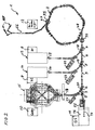
- FIG. 2 shows a schematic diagram of a particle accelerator 1 with components pointed to by the beam allocation device 21 is used in accordance with FIG.
- the particle accelerator 1 has an acceleration region 2 in the form a synchrotron, the ion packets on energies of about 4500 MeV accelerated. These ion packets are in an ion source 89 generated and a linear accelerator 56th pre-accelerated, as well as in a coupling region 47, in which also the exciter 33 is arranged in the accelerator ring 2 coupled.
- the irradiation rooms 13-15 are the Control rooms 8-10 assigned directly to the deflection magnets 18-20, and a jet break to the Effect capture chambers 22-25 in a few hundred milliseconds can. These deflection components 4-7 of the transport route 3 are thus not as fast as the jet break options through the spill abort components 32 and 33 in the irradiation ring Second
- the outputs of the ANDGATEs 63-66 are fed to an ORGATE 67 whose outputs are REQEX and REQBU each via a request line 34 to the exciter or the spill abort magnet of the spill abort system of the accelerator ring are connected,
- FIG. 4 shows a schematic diagram of a Grantscaria 68, the now from grant lines GRANTEX and GRANTBU from the Exciter or the spill abort magnet of the spill abort system over an ANDGATE 69 passed to corresponding ANDGATEs 70-73 Beyond this entrance of the ANDGATE 69 there are two more Have inputs, namely BZ1 to BZ4 and REQ1 to REQ4, which ensures that both a request signal to a the inputs REQ1 to REQ4, as well as a signal for confirmed, active beam target at one of the inputs BZ1 to BZ4 of the four ANDGATEs 70-73 is applied, so that at the output of this ANDGATEs a signal GRANT1 to GRANT4 via corresponding Grant lines 35 are returned to the control rooms can.
- FIG. 5 shows a schematic diagram of a spill-pause circuit 75.
- This Spillpause circuit 75 with the Spillpause effet 38 can be from all four control rooms of the three treatment rooms and only one quality assurance room used when a grant signal GRANT1 to GRANT4 the Spillabbruchiana the spill abort system is present.
- the spill pause circuit 75 has four ANDGATEs 76-79 on, each two inputs for a grenade signal GRANT1 up GRANT4 and a Spillsignal SPILL1 to SPILL4, wherein these signals via Grant effet 35 and Spillpause effet 38 to the ANDGATEs 76-79.
- FIG. 6 shows a schematic diagram of an interlock circuit 85 for processing interlock signals INTL1 to INTL4 via Interlock lines 37 through ANDGATEs 81-84 at their inputs at the same time a Grant signal GRANT1 to GRANT4 over the Grant lines 35 must be applied to one of the outputs of ANDGATEs 81-84 to the input of an ORGATE 86.
- the ORGATE 86 again has two outputs INTLEX and INTLBU, the to the exciter or to the spill abort magnet via interlock lines 37 lead.
- the interlock line 37 of the exciter and the spill stop magnet from all four irradiation places only be used when the grantsignal GRANT1 to GRANT4 of the spill abort elements. Does that have Accelerator sovereignty, he controls the exciter and the Spill abort magnets directly on, so that the Interlock effet 37 is not used by the accelerator.
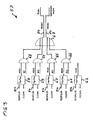
- FIG. 7 shows a schematic of a flowchart 95 of a flow control an arbitration unit.
- this flowchart 95 takes into account that a scheduler exists may or may not be. Accordingly, the changes Pass through flowchart 95.
- In flowchart 95 becomes the beam destination of the scheduler with the reference numeral SZ defines the requesting beam destination or the requesting one Control room marked with AZ and a confirmed, active beam target is indicated by the reference BZ.
- This process control receives the arbitration unit from the scheduler via a digital on / off module, the desired next request instance or the next requesting one Control room.
- the request instances listed in flowchart 95 with AZ1 to AZ4, correspond to the treatment rooms H1, H2, gantry and QS in that shown in FIG Block diagram.
- the request instance AZ5 corresponds to the Accelerator to the beam guidance to the beam destroyer of the accelerator and all released for the accelerator Radiation places belong.
- the request instance SZ6 means that at the moment there is no award of sovereignty, and the request instance SZ7 means that the Scheduler is not active, and does not supply defaults, so the arbitration unit independently awards the sovereignty. This allocation by the arbitration unit should then an all-around process in which the arbitration unit the request units or control rooms in turn the opportunity to make a reservation allows.
- the flowchart 95 for the flow control complements the processing of request, grant and interlock signals, the described above.
- the flow control of the arbitration unit reads according to the flowchart 95 of the Scheduler desired request instance or the corresponding Control room, also referred to as scheduler instance SI becomes a.
- scheduler instance SI becomes a.
- the irradiation entity BI to the request and Grant circuits passed and ensures in this way, that only the chosen place reserves the spill abort elements can.
- the interlock signal is not passed through the flow control influences.
Landscapes
- Health & Medical Sciences (AREA)
- Engineering & Computer Science (AREA)
- Biomedical Technology (AREA)
- Pathology (AREA)
- Nuclear Medicine, Radiotherapy & Molecular Imaging (AREA)
- Radiology & Medical Imaging (AREA)
- Life Sciences & Earth Sciences (AREA)
- Animal Behavior & Ethology (AREA)
- General Health & Medical Sciences (AREA)
- Public Health (AREA)
- Veterinary Medicine (AREA)
- Radiation-Therapy Devices (AREA)
- Particle Accelerators (AREA)
Abstract
Description
Entsprechend den Verbindungen zwischen Schaltlogik und Kontrollräumen bestehen entsprechende elektrische Verbindungen zwischen der Schaltlogik der Arbitrierungseinheit und dem Spillabbruchsystem des Beschleunigungsbereichs. Da jeweils eine Requestsignalleitung, eine Grantsignalleitung, eine Spillpauseleitung und eine Interlockleitung, sowohl mit dem Exciter als auch mit dem Spillabbruchmagneten vorhanden sind, ist die Anzahl der Signalleitungen zwischen Schaltlogik der Arbitrierungseinheit und dem Spillabbruchsystem doppelt ausgelegt, womit die Systemsicherheit weiter erhöht wird.
zunächst wird eine Reservierung der Teilchenstrahlhoheit, insbesondere eine Reservierung eines direkten Zugriffs auf ein Spillabbruchsystem des von allen Behandlungsräumen benötigten Beschleunigungsbereichs für eine geplante Dauer einer Bestrahlung durch einen der Kontrollräume beantragt. Anschließend wird eine sicherheitsrelevante Reservierung des Spillabbruchsystems durch eine elektronische Schaltungslogik einer Arbitrierungseinheit durchgeführt. Schließlich erfolgt ein Mitteilen der Reservierung an jeden Kontrollraum unter Zulassen nur eines Kontrollraums für einen Strahlabbruch über das Spillabbruchsystem.
- Figur 1
- zeigt ein Schema eines Blockschaltbildes einer Strahlzuteilungsvorrichtung gemäß einer Ausführungsform der Erfindung;
- Figur 2
- zeigt eine Prinzipskizze eines Teilchenbeschleunigers mit Komponenten, auf die von der Strahlzuteilungsvorrichtung zugegriffen wird;
- Figur 3
- zeigt eine Prinzipskizze einer Requestschaltung zum Verarbeiten von Requestsignalen über Requestleitungen;
- Figur 4
- zeigt eine Prinzipskizze einer Grantschaltung zur Verarbeitung von Grantsignalen über Grantleitungen;
- Figur 5
- zeigt eine Prinzipskizze einer Spillpause-Schaltung zur Verarbeitung von Spillpausesignalen über Spillpauseleitungen;
- Figur 6
- zeigt eine Prinzipskizze einer Interlockschaltung zur Verarbeitung von Interlocksignalen über Interlockleitungen;
- Figur 7
- zeigt ein Schema eines Flussdiagramms einer Ablaufsteuerung einer Arbitrierungseinheit.
- Figur 8
- zeigt eine Prinzipskizze der Serienschaltung von potenzialfreien Kontakten der Kontrollräume für einen Spillabbruch über einen Exciter des Beschleunigungsbereichs.
- Figur 9
- zeigt eine Prinzipskizze der Serienschaltung von potenzialfreien Kontakten der Kontrollräume für einen Spillabbruch über einen Spillabbruchmagneten des Beschleunigungsbereichs;
- Wenn eine Anforderungsinstanz bzw, ein Kontrollraum 8 bis 12 grundsätzlich alle Vorkehrungen getroffen hat, eine Bestrahlung zu beginnen, dann wird entweder auf Druck auf einen Knopf einer Konsole des Kontrollraums, oder durch ein von einem Rechner generiertes Signal eine Anforderung an die Arbitrierungseinheit 26 in Form eines Requestsignals über die Requestleitung 34 übermittelt. Insbesondere die Benutzer in dem Kontrollraum des bestrahlungsaktiven Behandlungsraumes, aber auch das Personal in anderen Kontrollräumen 8-12, erhalten eine optische Anzeige dieser Anforderung.
- Damit die Anforderungsinstanz die Hoheit über das Spillabbruchsystem 31 erhält, sind mehrere Bedingungen zu erfüllen:
- Es hat zunächst keine andere Anforderungsinstanz die Hoheit über das Spillabbruchsystem 31 des Beschleunigungsbereichs. Die Hoheit über das Spillabbruchsystem 31 wird erst neu vergeben, wenn die aktuelle Anforderungsinstanz mit ihrem bestrahlungsaktiven Bestrahlungsraum selber aktiv die Kontrolle abgibt.
- Der Scheduler 46 hat die Anforderungsinstanz als nächstes Ziel vorzugeben. Falls der Scheduler jedoch deaktiviert ist, werden die Zugriffsrechte reihum den Anforderungsinstanzen von der Arbitrierungseinheit 26 angeboten.
- Das Spillabbruchsystem 31 muss bereitstehen, damit eine Anforderungsinstanz die Hoheit über das Spillabbruchsystem 31 erhält.
- Die erfolgreiche Reservierung für einen Zugriff auf das Spillabbruchsystem 31 wird von beiden Elementen, nämlich dem Exciter 33 und dem Spillabbruchmagneten 32 des Spillabbruchsystems 31 quittiert, in Form eines Grantsignals über die Grantleitungen 35. Insbesondere die Benutzer des lokalen Kontrollraums, aber auch das Personal in allen anderen Kontrollräumen B-12, erhalten wiederum eine optische Anzeige dieser Reservierung.
- Während der laufenden Bestrahlung, das heißt, wenn ein Bestrahlungsraum bestrahlungsaktiv ist, kann die Anforderungsinstanz die beiden Komponenten des Spillabbruchsystems 31 mithilfe einer Spillpauseleitung 38 und alternativ über einen redundanten Signalpfad 39 bzw. 49 einer Interlockleitung jederzeit abschalten.
- Nach Ende einer Bestrahlung wird die Anforderung bzw. der "Request" von der Anforderungsinstanz bzw. den Kontrollräumen 8-12 explizit wieder zurückgenommen mit einem Clearsignal über die Clearleitung 36. Dieses löscht gleichzeitig auch das Grantsignal.
- 1
- Teilchenbeschleuniger
- 2
- Beschleunigerring
- 3
- Transportstrecke
- 4-7
- Ablenkkomponente
- 8
- Kontrollraum H1
- 9
- Kontrollraum H2
- 10
- Kontrollraum Gantry
- 11
- Kontrollraum Q2
- 12
- Kontrollraum, Beschleuniger
- 13
- Behandlungsraum
- 14
- Behandlungsraum
- 15
- Behandlungsraum (Gantry)
- 16
- Qualitätssicherzulgsraum
- 17
- Teilchenstrahl
- 18-20
- Ablenkmagnet
- 21
- Strahlzuteilungsvorrichtung
- 22-25
- Auffangkammer
- 26
- Arbitrierungseinheit
- 27
- Schaltlogik
- 28
- Überwachungseinheit
- 29
- Ablaufsteuerung
- 30
- Signalleitung
- 31
- Spillabbruchsystem
- 32
- Spillabbruchmagnet
- 33
- Exciter
- 34
- Requestsignalleitung
- 35
- Grantsignalleitung
- 36
- Clearsignalleitung
- 37
- Interlockleitung
- 38
- Spillpauseleitung
- 39
- redundanter Signalpfad zum Exciter
- 40
- Eingangssignalverbindung der Überwachungseinheit
- 41
- Eingangssignalverbindung der Überwachungseinheit
- 42
- Interlocksignal der Überwachungseinheit
- 43
- Interlocksignal (potentialfrei) der Überwachungseinheit
- 44
- Interlocksignal der Überwachungseinheit
- 45
- Interlocksignal (potentialfrei) der Überwachungseinheit
- 46
- Scheduler
- 47
- Einkopplungsbereich
- 48
- Auskopplungsbereich
- 49
- redundanter Signalpfad zum Spillabbruchmagneten
- 50
- Schaltelemente eines Kontrollraums
- 51
- Signalbus der Kontrollräume
- 52
- Signalbus der Ablaufsteuerung
- 53
- Signalbus des Schedulers
- 54
- Ausgangssignalleitung der Ablaufsteuerung
- 55
- Ausgangssignalleitung des Schedulers
- 56
- Linearbeschleuniger
- 57
- Requestschaltung
- 58-62
- Flip-Flop der Request-Schaltung
- 63-66
- ANDGATEs der Request-Schaltung
- 67
- ORGATE der Request-Schaltung
- 68
- Grant-Schaltung
- 69
- ANDGATE der Grant-Schaltung
- 70-74
- ANDGATEs der Grant-Schaltung
- 75
- Spillpause-Schaltung
- 76-79
- ANDGATEs der Spillpause-Schaltung
- 80
- ORGATE der Spillpause-Schaltung
- 81-84
- ANDGATEs der Interlock-Schaltung
- 85
- Interlock-Schaltung
- 86
- ORGATE der Interlock-Schaltung
- 87
- Serienschalter zum Exciter
- 88
- Serienschalter zum Spillabbruchmagnet
- 89
- Ionenquelle
- 95
- Flussdiagramm
Claims (21)
- Strahlzuteilungsvorrichtung für medizinische Teilchenbeschleuniger (1), wobei der Teilchenbeschleuniger (1) mindestens einen Beschleunigungsbereich (2), eine Transportstrecke (3) und Ablenkkomponenten (4 bis 7) aufweist, über welche mehrere jeweils einen Kontrollraum (8 bis 10) aufweisende Behandlungsräume (13 bis 15) mit einem Teilchenstrahl (17) aus Ionenpaketen versorgt werden
dadurch gekennzeichnet, dass
die Strahlzuteilungsvorrichtung (21) eine Arbitrierungseinheit (26) mit Schaltlogik (27), Überwachungseinheit (28) und Ablaufsteuerung (29) aufweist, die über Signalleitungen (30) mit einem Spillabbruchsystem (31), das mindestens zwei schnelle Spillabbruchelemente im Beschleunigungsbereich und/oder in der allen Bestrahlungsplätzen gemeinsamen Strahlführung aufweist, elektrisch in Verbindung steht, wobei die Strahlzuteilungsvorrichtung (21) einen direkten Zugriff des Kontrollraums (8 bis 12) des bestrahlungsaktiven Behandlungsraums (13 bis 15) für einen Teilchenstrahlabbruch bei Gefahr innerhalb von Mikrosekunden bereitstellt. - Strahlzuteilungsvorrichtung nach Anspruch 1,
dadurch gekennzeichnet, dass
das Spillabbruchsystem einen Spillabbruchmagneten aufweist. - Strahlzuteilungsvorrichtung nach Anspruch 1 oder Anspruch 2,
dadurch gekennzeichnet, dass
die Strahlzuteilungsvorrichtung Zugriff auf einen Exciter hat. - Strahlzuteilungsvorrichtung nach einem der vorhergehenden Ansprüche,
dadurch gekennzeichnet, dass
jeder Kontrollraum (8 bis 12) eines Behandlungsraumes (13 bis 15) und/oder eines Qualitätssicherungsraumes (16), sowie des Teilchenbeschleunigers (1) eine Requestsignalleitung (34) zu der Schaltlogik (27) der Arbitrierungseinheit (26) zur Anfrage einer Übertragung einer Strahlhoheit mit Zugriffsberechtigung auf den Exciter (33) und/oder den Spillabbruchmagneten (32) des Beschleunigungsbereichs (2) auf den Kontrollraum (8 bis 12) aufweist. - Strahlzuteilungsvorrichtung nach einem der vorhergehenden Ansprüche,
dadurch gekennzeichnet, dass
jeder Kontrollraum (8 bis 11) eines Behandlungsraumes (13 bis 15) und/oder eines Qualitätssicherungsraumes (16), sowie des Teilchenbeschleunigers (1) eine Grantsignalleitung (35) zu der Schaltlogik (27) der Arbitrierungseinheit (26) zur Bestätigung einer Übertragung einer Zugriffsberechtigung auf den Exciter (33) und/oder den Spillabbruchmagneten (32) des Beschleunigungsbereichs (2) für den Kontrollraum (8 bis 12) während einer bestrahlungsaktiven Phase aufweist. - Strahlzuteilungsvorrichtung nach einem der vorhergehenden Ansprüche,
dadurch gekennzeichnet, dass
jeder Kontrollraum (8 bis 11) eines Behandlungsraumes (13 bis 15) und/oder eines Qualitätssicherungsraumes (16) eine Clearsignalleitung (36) zu der Schaltlogik (27) der Arbitrierungseinheit (26) zur Bestätigung eines erfolgten Abbruchs der Bestrahlung und zur Löschung einer Zugriffsreservierung auf den Exciter (33) und/oder den Spillabbruchmagneten (32) des Beschleunigungsbereichs (2) für den Kontrollraum (8 bis 11) aufweist. - Strahlzuteilungsvorrichtung nach einem der vorhergehenden Ansprüche,
dadurch gekennzeichnet, dass
jeder Kontrollraum (B bis 11) eines Behandlungsraumes (13 bis 15) und/oder eines Qualitätssicherungsraumes (16) eine Interlockleitung (37) zu der Schaltlogik (27) der Arbitrierungseinheit (26) zum Abbruch der Bestrahlung durch unmittelbaren zugriff des Kontrollraumes (8 bis 11) auf den Exciter (33) und/oder den Spillabbruchmagneten (32) des Beschleunigungsbereichs (2) aufweist. - Strahlzuteilungsvorrichtung nach einem der vorhergehenden Ansprüche,
dadurch gekennzeichnet, dass
jeder Kontrollraum (8 bis 11) eines Behandlungsraumes (13 bis 15) und/oder eines Qualitätssicherungsraumes (16) eine Spillpauseleitung (38) zu der Schaltlogik (27) der Arbitrierungseinheit (26) zum Abbruch der Bestrahlung durch unmittelbaren Zugriff des Kontrollraumes (8 bis 11) auf den Exciter (33) und/oder den Spillabbruchmagneten (32) des Beschleunigungs (2) unter Beibehaltung einer Zugriffsreservierung aufweist. - Strahlzuteilungsvorrichtung nach einem der vorhergehenden Ansprüche,
dadurch gekennzeichnet, dass
die Schaltlogik (27) der Arbitrierungseinheit (26) jeweils eine Requestsignalleitung (34), eine Grantsignalleitung (35), eine Spillpauseleitung (38), eine Interlockleitung (37), eine Clearsignalleitung (36) aufweist, über welche die Schaltlogik (27) mit den Komponenten (32, 33) des Spillabbruchsystems (31) elektrisch in Verbindung steht. - Strahlzuteilungsvorrichtung nach einem der vorhergehenden Ansprüche,
dadurch gekennzeichnet, dass
die Überwachungseinheit (28) der Arbitrierungseinheit (26) über Eingangssignalverbindungen (40, 41) von der Schaltlogik (27) und der Ablaufsteuerung (29) Signale empfängt und über Ausgangssignalverbindungen (42 bis 45) mit dem Spillabbruchsystem (31) des Beschleunigungsbereichs (2) verbunden ist. - Strahlzuteilungsvorrichtung nach einem der vorhergehenden Ansprüche,
dadurch gekennzeichnet, dass
ein Scheduler (46) mit der Schaltlogik (27) der Arbitrierungseinheit (26) verbunden ist und über die Ablaufsteuerung (29) der Arbitrierungseinheit (26) das Abarbeiten einer im Scheduler (46) erstellten Warteschlange von Bestrahlungsanforderungen der Kontrollräume (8 bis 12) steuert. - Strahlzuteilungsvorrichtung nach einem der vorhergehenden Ansprüche,
dadurch gekennzeichnet, dass
der Exciter (33) eine Hochfrequenzresonanzkomponente für Ionenpakete im Einkopplungsbereich (47) des Beschleunigers (2) ist und durch Verstellen bzw. Fehlanpassen der Resonanzabstimmung einen Strahlabbruch in Mikrosekunden auslöst. - Strahlzuteilungsvorrichtung nach einem der vorhergehenden Ansprüche,
dadurch gekennzeichnet, dass
der Spillabbruchmagnet (32) ein Strahlführungsmagnet im Auskopplungsbereich (48) des Beschleunigungsbereichs (2) ist. - Strahlzuteilungsvorrichtung nach einem der vorhergehenden Ansprüche,
dadurch gekennzeichnet, dass
die Strahlzuteilungsvorrichtung (21) eine Steuerung und Verwaltung der Zuteilung eines Teilchenstrahls (17) eines Bestrahlungssystems mit Ionenschreibstrahl einer Ionenstrahlabtastvorrichtung für ein Zielvolumen aufweist. - Strahlzuteilungsvorrichtung für medizinische Teilchenbeschleuniger (1), wobei der Teilchenbeschleuniger (1) mindestens einen Beschleunigungsbereich (2), eine Transportstrecke (3) und Ablenkkomponenten (4 bis 7) aufweist, über welche mehrere jeweils einen Kontrollraum (B bis 10) aufweisende Behandlungsräume (13 bis 15) mit einem Teilchenstrahl (17) aus Ionenpaketen versorgt werden
dadurch gekennzeichnet, dass
die Strahlzuteilungsvorrichtung (21) eine Arbitrierungseinheit (26) mit Schaltlogik (27), Überwachungseinheit (28) und Ablaufsteuerung (29) aufweist, die über Signalleitungen (30) mit einem Spillabbruchsystem (31), das mindestens zwei schnelle Spillabbruchelemente im Beschleunigungsbereich und/oder in der allen Bestrahlungsplätzen gemeinsamen Strahlführung aufweist, elektrisch in Verbindung steht, wobei die Kontrollräume (8 bis 12) seriell mit einer potenzialfreien Interlockleitung (39) zu dem Spillabbruchsystem (31) verbunden sind, und die Strahlzuteilungsvorrichtung (21) einen direkten Zugriff auf den bestrahlungsaktiven Behandlungsraums (13 bis 15) für einen Teilchenstrahlabbruch bei Gefahr innerhalb von Mikrosekunden bereitstellt. - Strahlzuteilungsverfahren für medizinische Teilchenbeschleuniger (1), wobei der Teilchenbeschleuniger (1) mindestens einen Beschleunigungsbereich (2), eine Transportstrecke (3) und Ablenkkomponenten (4 bis 7) aufweist, über welche mehrere jeweils einen Kontrollraum (8 bis 10) aufweisende Behandlungsräume (13 bis 15) mit einem Teilchenstrahl (17) aus Ionenpaketen sequenziell versorgt werden, wobei das Strahlzuteilungsverfahren folgende Verfahrenschritte aufweist:wobei die Arbitrierungseinheit (26) bei gleichzeitiger Strahlreservierungsanforderung mehrerer Kontrollräume (8 bis 12) entscheidet, welcher Kontrollraum (8 bis 12) eines Bestrahlungsplatzes (13 bis 15) die Reservierung vornehmen kann undAnfordern einer Reservierung der Teilchenstrahlhoheit insbesondere einer Reservierung eines direkten Zugriffs auf ein Spillabbruchsystem (31) des von allen Behandlungsräumen (13 bis 15) benötigten Beschleunigungsbereichs (2) für eine geplante Dauer einer Bestrahlung durch einen der Kontrollräume (8 bis 12);Durchführen einer sicherheitsrelevanten Reservierung des Spillabbruchsystems (31) durch eine elektronische Schaltlogik (27) einer Arbitrierungseinheit (26);Mitteilen der erfolgten Reservierung an jeden Kontrollraum (8 bis 12) unter Zulassen nur eines Kontrollraumes (8 bis 12) für einen Strahlabbruch über das Spillabbruchsystem (31);Bereithalten eines von der Arbitrierungseinheit (26) unabhängigen und unmittelbaren redundanten Signalpfades (39, 49) zum Spillabbruchsystem (31) des Beschleunigungs (2) für die Kontrollräume (8 bis 12), wobei die Schaltelemente (50) der Kontrollräume (8 bis 12) in Reihe geschaltet sind,
wobei trotz Verlust einer Reservierung ein Spillabbruch von jedem Kontrollraum (8 bis 12) über den redundanten Signalpfad (39, 49) ausgelöst werden kann. - Strahlzuteilungsverfahren nach Anspruch 16,
dadurch gekennzeichnet, dass
die Strahlhoheit erst dann von einem aktiven Kontrollraum (8 bis 12) zu einem anderen Kontrollraum (8 bis 12) übergeben wird, wenn der aktuelle Kontrollraum (8 bis 12) die Kontrolle über den Teilchenstrahl (17) aktiv abgibt. - Strahlzuteilungsverfahren nach Anspruch 16 oder Anspruch 17,
dadurch gekennzeichnet, dass
das Spillabbruchsystem (31) des Beschleunigerringes (2) für eine kurzzeitige Strahlabschaltung aktiviert wird. - Strahlzuteilungsverfahren nach einem der Ansprüche 16 bis 18,
dadurch gekennzeichnet, dass
ein Kontrollraum (12) für den Teilchenbeschleuniger (1) eine Reservierung für das Spillabbruchsystem (31) vornimmt, wenn gewährleistet ist, dass entweder kein Strahl zu den Bestrahlungsräumen (13 bis 15) gelangt oder dass sich dort kein Patient aufhält. - Strahlzuteilungsverfahren nach einem der Ansprüche 16 bis 19,
dadurch gekennzeichnet, dass
der Status aller Reservierungen, Zugriffsberechtigungen und Quittungen durch eine Überwachungseinheit (28) der Arbitrierungseinheit (26) überprüft wird und bei Inkonsistenz eine Abschaltung über den redundanten Signalpfad (39, 49) durchgeführt wird. - Strahlzuteilungsverfahren nach einem der Ansprüche 16 bis 20,
dadurch gekennzeichnet, dass
durch ein nicht sicherheitsrelevantes Mikroprozessorsystem als Scheduler (46) eine Abfolge der Vergabe von Reservierungen des Spillabbruchsystems (31) der Arbitrierungseinheit (26) mitgeteilt wird und bei Fehlen des Mikroprozessorsystems oder bei Fehlen von Vergaben die Arbitrierungseinheit (26) der Kontrollräume (8 bis 12) reihum die Gelegenheit gibt, eine Reservierung vorzunehmen.
Priority Applications (1)
| Application Number | Priority Date | Filing Date | Title |
|---|---|---|---|
| EP07004468A EP1785162B1 (de) | 2004-05-19 | 2005-05-13 | Medizinsche Bestrahlungsanlage mit einem Teilchenbeschleuniger |
Applications Claiming Priority (4)
| Application Number | Priority Date | Filing Date | Title |
|---|---|---|---|
| DE102004025263 | 2004-05-19 | ||
| DE102004025263 | 2004-05-19 | ||
| DE102004027071 | 2004-06-02 | ||
| DE102004027071A DE102004027071A1 (de) | 2004-05-19 | 2004-06-02 | Strahlzuteilungsvorrichtung und Strahlzuteilungsverfahren für medizinische Teilchenbeschleuniger |
Related Child Applications (1)
| Application Number | Title | Priority Date | Filing Date |
|---|---|---|---|
| EP07004468A Division EP1785162B1 (de) | 2004-05-19 | 2005-05-13 | Medizinsche Bestrahlungsanlage mit einem Teilchenbeschleuniger |
Publications (2)
| Publication Number | Publication Date |
|---|---|
| EP1598094A1 true EP1598094A1 (de) | 2005-11-23 |
| EP1598094B1 EP1598094B1 (de) | 2007-03-07 |
Family
ID=34936492
Family Applications (2)
| Application Number | Title | Priority Date | Filing Date |
|---|---|---|---|
| EP05010450A Not-in-force EP1598094B1 (de) | 2004-05-19 | 2005-05-13 | Strahlzuteilungsverfahren für medizinische Teilchenbeschleuniger |
| EP07004468A Not-in-force EP1785162B1 (de) | 2004-05-19 | 2005-05-13 | Medizinsche Bestrahlungsanlage mit einem Teilchenbeschleuniger |
Family Applications After (1)
| Application Number | Title | Priority Date | Filing Date |
|---|---|---|---|
| EP07004468A Not-in-force EP1785162B1 (de) | 2004-05-19 | 2005-05-13 | Medizinsche Bestrahlungsanlage mit einem Teilchenbeschleuniger |
Country Status (5)
| Country | Link |
|---|---|
| US (2) | US7351988B2 (de) |
| EP (2) | EP1598094B1 (de) |
| JP (1) | JP2005353587A (de) |
| AT (2) | ATE355871T1 (de) |
| DE (3) | DE102004027071A1 (de) |
Cited By (1)
| Publication number | Priority date | Publication date | Assignee | Title |
|---|---|---|---|---|
| EP2073612B1 (de) * | 2007-12-21 | 2017-09-27 | Hitachi, Ltd. | Bestrahlungsvorrichtung für Geladene Teilchen |
Families Citing this family (127)
| Publication number | Priority date | Publication date | Assignee | Title |
|---|---|---|---|---|
| JP3859605B2 (ja) * | 2003-03-07 | 2006-12-20 | 株式会社日立製作所 | 粒子線治療システム及び粒子線出射方法 |
| DE102004027071A1 (de) * | 2004-05-19 | 2006-01-05 | Gesellschaft für Schwerionenforschung mbH | Strahlzuteilungsvorrichtung und Strahlzuteilungsverfahren für medizinische Teilchenbeschleuniger |
| EP3557956A1 (de) | 2004-07-21 | 2019-10-23 | Mevion Medical Systems, Inc. | Programmierbarer funkfrequenzwellenformgenerator für ein synchrozyklotron |
| JP4489529B2 (ja) * | 2004-07-28 | 2010-06-23 | 株式会社日立製作所 | 粒子線治療システム及び粒子線治療システムの制御システム |
| DE102005044409B4 (de) * | 2005-09-16 | 2007-11-29 | Siemens Ag | Partikeltherapieanlage und Verfahren zur Ausbildung eines Strahlpfads für einen Bestrahlungsvorgang in einer Partikeltherapieanlage |
| DE102005044408B4 (de) * | 2005-09-16 | 2008-03-27 | Siemens Ag | Partikeltherapieanlage, Verfahren und Vorrichtung zur Anforderung eines Partikelstrahls |
| ES2594619T3 (es) | 2005-11-18 | 2016-12-21 | Mevion Medical Systems, Inc. | Radioterapia con partículas cargadas |
| US8581523B2 (en) | 2007-11-30 | 2013-11-12 | Mevion Medical Systems, Inc. | Interrupted particle source |
| US8933650B2 (en) | 2007-11-30 | 2015-01-13 | Mevion Medical Systems, Inc. | Matching a resonant frequency of a resonant cavity to a frequency of an input voltage |
| US7953205B2 (en) * | 2008-05-22 | 2011-05-31 | Vladimir Balakin | Synchronized X-ray / breathing method and apparatus used in conjunction with a charged particle cancer therapy system |
| US10070831B2 (en) | 2008-05-22 | 2018-09-11 | James P. Bennett | Integrated cancer therapy—imaging apparatus and method of use thereof |
| US9910166B2 (en) | 2008-05-22 | 2018-03-06 | Stephen L. Spotts | Redundant charged particle state determination apparatus and method of use thereof |
| US8598543B2 (en) | 2008-05-22 | 2013-12-03 | Vladimir Balakin | Multi-axis/multi-field charged particle cancer therapy method and apparatus |
| AU2009249863B2 (en) * | 2008-05-22 | 2013-12-12 | Vladimir Yegorovich Balakin | Multi-field charged particle cancer therapy method and apparatus |
| US9782140B2 (en) | 2008-05-22 | 2017-10-10 | Susan L. Michaud | Hybrid charged particle / X-ray-imaging / treatment apparatus and method of use thereof |
| US8373145B2 (en) | 2008-05-22 | 2013-02-12 | Vladimir Balakin | Charged particle cancer therapy system magnet control method and apparatus |
| US8188688B2 (en) | 2008-05-22 | 2012-05-29 | Vladimir Balakin | Magnetic field control method and apparatus used in conjunction with a charged particle cancer therapy system |
| EP2283709B1 (de) | 2008-05-22 | 2018-07-11 | Vladimir Yegorovich Balakin | Patientenpositionierungsvorrichtung für die krebstherapie mit geladenen teilchen |
| US8129699B2 (en) * | 2008-05-22 | 2012-03-06 | Vladimir Balakin | Multi-field charged particle cancer therapy method and apparatus coordinated with patient respiration |
| US9737734B2 (en) | 2008-05-22 | 2017-08-22 | Susan L. Michaud | Charged particle translation slide control apparatus and method of use thereof |
| US7940894B2 (en) * | 2008-05-22 | 2011-05-10 | Vladimir Balakin | Elongated lifetime X-ray method and apparatus used in conjunction with a charged particle cancer therapy system |
| US8374314B2 (en) | 2008-05-22 | 2013-02-12 | Vladimir Balakin | Synchronized X-ray / breathing method and apparatus used in conjunction with a charged particle cancer therapy system |
| CN102172106B (zh) * | 2008-05-22 | 2015-09-02 | 弗拉迪米尔·叶戈罗维奇·巴拉金 | 带电粒子癌症疗法束路径控制方法和装置 |
| US10029122B2 (en) | 2008-05-22 | 2018-07-24 | Susan L. Michaud | Charged particle—patient motion control system apparatus and method of use thereof |
| WO2009142547A2 (en) * | 2008-05-22 | 2009-11-26 | Vladimir Yegorovich Balakin | Charged particle beam acceleration method and apparatus as part of a charged particle cancer therapy system |
| US9095040B2 (en) | 2008-05-22 | 2015-07-28 | Vladimir Balakin | Charged particle beam acceleration and extraction method and apparatus used in conjunction with a charged particle cancer therapy system |
| US8378321B2 (en) * | 2008-05-22 | 2013-02-19 | Vladimir Balakin | Charged particle cancer therapy and patient positioning method and apparatus |
| US8089054B2 (en) | 2008-05-22 | 2012-01-03 | Vladimir Balakin | Charged particle beam acceleration and extraction method and apparatus used in conjunction with a charged particle cancer therapy system |
| US20090314960A1 (en) * | 2008-05-22 | 2009-12-24 | Vladimir Balakin | Patient positioning method and apparatus used in conjunction with a charged particle cancer therapy system |
| US9168392B1 (en) | 2008-05-22 | 2015-10-27 | Vladimir Balakin | Charged particle cancer therapy system X-ray apparatus and method of use thereof |
| US8045679B2 (en) * | 2008-05-22 | 2011-10-25 | Vladimir Balakin | Charged particle cancer therapy X-ray method and apparatus |
| US8975600B2 (en) | 2008-05-22 | 2015-03-10 | Vladimir Balakin | Treatment delivery control system and method of operation thereof |
| US9937362B2 (en) | 2008-05-22 | 2018-04-10 | W. Davis Lee | Dynamic energy control of a charged particle imaging/treatment apparatus and method of use thereof |
| US8569717B2 (en) * | 2008-05-22 | 2013-10-29 | Vladimir Balakin | Intensity modulated three-dimensional radiation scanning method and apparatus |
| US8093564B2 (en) * | 2008-05-22 | 2012-01-10 | Vladimir Balakin | Ion beam focusing lens method and apparatus used in conjunction with a charged particle cancer therapy system |
| US9682254B2 (en) | 2008-05-22 | 2017-06-20 | Vladimir Balakin | Cancer surface searing apparatus and method of use thereof |
| US8436327B2 (en) * | 2008-05-22 | 2013-05-07 | Vladimir Balakin | Multi-field charged particle cancer therapy method and apparatus |
| US8969834B2 (en) | 2008-05-22 | 2015-03-03 | Vladimir Balakin | Charged particle therapy patient constraint apparatus and method of use thereof |
| US7943913B2 (en) | 2008-05-22 | 2011-05-17 | Vladimir Balakin | Negative ion source method and apparatus used in conjunction with a charged particle cancer therapy system |
| US8309941B2 (en) * | 2008-05-22 | 2012-11-13 | Vladimir Balakin | Charged particle cancer therapy and patient breath monitoring method and apparatus |
| US8144832B2 (en) * | 2008-05-22 | 2012-03-27 | Vladimir Balakin | X-ray tomography method and apparatus used in conjunction with a charged particle cancer therapy system |
| US9155911B1 (en) | 2008-05-22 | 2015-10-13 | Vladimir Balakin | Ion source method and apparatus used in conjunction with a charged particle cancer therapy system |
| US8373143B2 (en) * | 2008-05-22 | 2013-02-12 | Vladimir Balakin | Patient immobilization and repositioning method and apparatus used in conjunction with charged particle cancer therapy |
| US9744380B2 (en) | 2008-05-22 | 2017-08-29 | Susan L. Michaud | Patient specific beam control assembly of a cancer therapy apparatus and method of use thereof |
| US8718231B2 (en) | 2008-05-22 | 2014-05-06 | Vladimir Balakin | X-ray tomography method and apparatus used in conjunction with a charged particle cancer therapy system |
| US8288742B2 (en) * | 2008-05-22 | 2012-10-16 | Vladimir Balakin | Charged particle cancer therapy patient positioning method and apparatus |
| US9737733B2 (en) | 2008-05-22 | 2017-08-22 | W. Davis Lee | Charged particle state determination apparatus and method of use thereof |
| US8519365B2 (en) * | 2008-05-22 | 2013-08-27 | Vladimir Balakin | Charged particle cancer therapy imaging method and apparatus |
| US9056199B2 (en) | 2008-05-22 | 2015-06-16 | Vladimir Balakin | Charged particle treatment, rapid patient positioning apparatus and method of use thereof |
| US8378311B2 (en) | 2008-05-22 | 2013-02-19 | Vladimir Balakin | Synchrotron power cycling apparatus and method of use thereof |
| US8624528B2 (en) * | 2008-05-22 | 2014-01-07 | Vladimir Balakin | Method and apparatus coordinating synchrotron acceleration periods with patient respiration periods |
| US10092776B2 (en) | 2008-05-22 | 2018-10-09 | Susan L. Michaud | Integrated translation/rotation charged particle imaging/treatment apparatus and method of use thereof |
| US8373146B2 (en) * | 2008-05-22 | 2013-02-12 | Vladimir Balakin | RF accelerator method and apparatus used in conjunction with a charged particle cancer therapy system |
| MX2010012716A (es) * | 2008-05-22 | 2011-07-01 | Vladimir Yegorovich Balakin | Metodo y aparato de rayos x usados en conjunto con un sistema de terapia contra el cancer mediante particulas cargadas. |
| US10143854B2 (en) | 2008-05-22 | 2018-12-04 | Susan L. Michaud | Dual rotation charged particle imaging / treatment apparatus and method of use thereof |
| US9044600B2 (en) | 2008-05-22 | 2015-06-02 | Vladimir Balakin | Proton tomography apparatus and method of operation therefor |
| US8642978B2 (en) * | 2008-05-22 | 2014-02-04 | Vladimir Balakin | Charged particle cancer therapy dose distribution method and apparatus |
| US8399866B2 (en) | 2008-05-22 | 2013-03-19 | Vladimir Balakin | Charged particle extraction apparatus and method of use thereof |
| EP2283705B1 (de) | 2008-05-22 | 2017-12-13 | Vladimir Yegorovich Balakin | Vorrichtung zur extraktion eines strahls geladener teilchen zur verwendung in verbindung mit einem krebstherapiesystem mit geladenen teilchen |
| US9974978B2 (en) | 2008-05-22 | 2018-05-22 | W. Davis Lee | Scintillation array apparatus and method of use thereof |
| US10684380B2 (en) | 2008-05-22 | 2020-06-16 | W. Davis Lee | Multiple scintillation detector array imaging apparatus and method of use thereof |
| US9737272B2 (en) | 2008-05-22 | 2017-08-22 | W. Davis Lee | Charged particle cancer therapy beam state determination apparatus and method of use thereof |
| US8901509B2 (en) * | 2008-05-22 | 2014-12-02 | Vladimir Yegorovich Balakin | Multi-axis charged particle cancer therapy method and apparatus |
| US9498649B2 (en) | 2008-05-22 | 2016-11-22 | Vladimir Balakin | Charged particle cancer therapy patient constraint apparatus and method of use thereof |
| US9579525B2 (en) | 2008-05-22 | 2017-02-28 | Vladimir Balakin | Multi-axis charged particle cancer therapy method and apparatus |
| US8178859B2 (en) | 2008-05-22 | 2012-05-15 | Vladimir Balakin | Proton beam positioning verification method and apparatus used in conjunction with a charged particle cancer therapy system |
| US8129694B2 (en) * | 2008-05-22 | 2012-03-06 | Vladimir Balakin | Negative ion beam source vacuum method and apparatus used in conjunction with a charged particle cancer therapy system |
| US10548551B2 (en) | 2008-05-22 | 2020-02-04 | W. Davis Lee | Depth resolved scintillation detector array imaging apparatus and method of use thereof |
| US9981147B2 (en) | 2008-05-22 | 2018-05-29 | W. Davis Lee | Ion beam extraction apparatus and method of use thereof |
| US8710462B2 (en) * | 2008-05-22 | 2014-04-29 | Vladimir Balakin | Charged particle cancer therapy beam path control method and apparatus |
| US9177751B2 (en) | 2008-05-22 | 2015-11-03 | Vladimir Balakin | Carbon ion beam injector apparatus and method of use thereof |
| US9616252B2 (en) | 2008-05-22 | 2017-04-11 | Vladimir Balakin | Multi-field cancer therapy apparatus and method of use thereof |
| US7939809B2 (en) | 2008-05-22 | 2011-05-10 | Vladimir Balakin | Charged particle beam extraction method and apparatus used in conjunction with a charged particle cancer therapy system |
| US8198607B2 (en) * | 2008-05-22 | 2012-06-12 | Vladimir Balakin | Tandem accelerator method and apparatus used in conjunction with a charged particle cancer therapy system |
| US8368038B2 (en) | 2008-05-22 | 2013-02-05 | Vladimir Balakin | Method and apparatus for intensity control of a charged particle beam extracted from a synchrotron |
| US8907309B2 (en) | 2009-04-17 | 2014-12-09 | Stephen L. Spotts | Treatment delivery control system and method of operation thereof |
| US8637833B2 (en) | 2008-05-22 | 2014-01-28 | Vladimir Balakin | Synchrotron power supply apparatus and method of use thereof |
| US9855444B2 (en) | 2008-05-22 | 2018-01-02 | Scott Penfold | X-ray detector for proton transit detection apparatus and method of use thereof |
| US8896239B2 (en) * | 2008-05-22 | 2014-11-25 | Vladimir Yegorovich Balakin | Charged particle beam injection method and apparatus used in conjunction with a charged particle cancer therapy system |
| WO2010101489A1 (en) | 2009-03-04 | 2010-09-10 | Zakrytoe Aktsionernoe Obshchestvo Protom | Multi-field charged particle cancer therapy method and apparatus |
| US8625739B2 (en) | 2008-07-14 | 2014-01-07 | Vladimir Balakin | Charged particle cancer therapy x-ray method and apparatus |
| US8229072B2 (en) | 2008-07-14 | 2012-07-24 | Vladimir Balakin | Elongated lifetime X-ray method and apparatus used in conjunction with a charged particle cancer therapy system |
| US8627822B2 (en) * | 2008-07-14 | 2014-01-14 | Vladimir Balakin | Semi-vertical positioning method and apparatus used in conjunction with a charged particle cancer therapy system |
| US11648420B2 (en) | 2010-04-16 | 2023-05-16 | Vladimir Balakin | Imaging assisted integrated tomography—cancer treatment apparatus and method of use thereof |
| US10188877B2 (en) | 2010-04-16 | 2019-01-29 | W. Davis Lee | Fiducial marker/cancer imaging and treatment apparatus and method of use thereof |
| US10349906B2 (en) | 2010-04-16 | 2019-07-16 | James P. Bennett | Multiplexed proton tomography imaging apparatus and method of use thereof |
| US10638988B2 (en) | 2010-04-16 | 2020-05-05 | Scott Penfold | Simultaneous/single patient position X-ray and proton imaging apparatus and method of use thereof |
| US10179250B2 (en) | 2010-04-16 | 2019-01-15 | Nick Ruebel | Auto-updated and implemented radiation treatment plan apparatus and method of use thereof |
| US10625097B2 (en) | 2010-04-16 | 2020-04-21 | Jillian Reno | Semi-automated cancer therapy treatment apparatus and method of use thereof |
| US10086214B2 (en) | 2010-04-16 | 2018-10-02 | Vladimir Balakin | Integrated tomography—cancer treatment apparatus and method of use thereof |
| US10376717B2 (en) | 2010-04-16 | 2019-08-13 | James P. Bennett | Intervening object compensating automated radiation treatment plan development apparatus and method of use thereof |
| US10556126B2 (en) | 2010-04-16 | 2020-02-11 | Mark R. Amato | Automated radiation treatment plan development apparatus and method of use thereof |
| US10518109B2 (en) | 2010-04-16 | 2019-12-31 | Jillian Reno | Transformable charged particle beam path cancer therapy apparatus and method of use thereof |
| US10555710B2 (en) | 2010-04-16 | 2020-02-11 | James P. Bennett | Simultaneous multi-axes imaging apparatus and method of use thereof |
| US9737731B2 (en) | 2010-04-16 | 2017-08-22 | Vladimir Balakin | Synchrotron energy control apparatus and method of use thereof |
| US10751551B2 (en) | 2010-04-16 | 2020-08-25 | James P. Bennett | Integrated imaging-cancer treatment apparatus and method of use thereof |
| US10589128B2 (en) | 2010-04-16 | 2020-03-17 | Susan L. Michaud | Treatment beam path verification in a cancer therapy apparatus and method of use thereof |
| JP5347070B2 (ja) * | 2010-09-09 | 2013-11-20 | 三菱電機株式会社 | 粒子線治療装置 |
| US8700228B2 (en) * | 2011-03-29 | 2014-04-15 | Sumitomo Heavy Industries, Ltd. | Beam scheduler and beam allocation method of beam scheduler |
| US8963112B1 (en) | 2011-05-25 | 2015-02-24 | Vladimir Balakin | Charged particle cancer therapy patient positioning method and apparatus |
| JP6254600B2 (ja) | 2012-09-28 | 2017-12-27 | メビオン・メディカル・システムズ・インコーポレーテッド | 粒子加速器 |
| EP2900326B1 (de) | 2012-09-28 | 2019-05-01 | Mevion Medical Systems, Inc. | Steuerung einer partikeltherapie |
| TW201424466A (zh) | 2012-09-28 | 2014-06-16 | Mevion Medical Systems Inc | 磁場再生器 |
| TW201434508A (zh) | 2012-09-28 | 2014-09-16 | Mevion Medical Systems Inc | 一粒子束之能量調整 |
| WO2014052721A1 (en) | 2012-09-28 | 2014-04-03 | Mevion Medical Systems, Inc. | Control system for a particle accelerator |
| WO2014052718A2 (en) | 2012-09-28 | 2014-04-03 | Mevion Medical Systems, Inc. | Focusing a particle beam |
| US10254739B2 (en) | 2012-09-28 | 2019-04-09 | Mevion Medical Systems, Inc. | Coil positioning system |
| EP2901823B1 (de) | 2012-09-28 | 2021-12-08 | Mevion Medical Systems, Inc. | Steuerung der intensität eines partikelstrahls |
| JP6523957B2 (ja) | 2012-09-28 | 2019-06-05 | メビオン・メディカル・システムズ・インコーポレーテッド | 磁場を変更するための磁性シム |
| US8933651B2 (en) | 2012-11-16 | 2015-01-13 | Vladimir Balakin | Charged particle accelerator magnet apparatus and method of use thereof |
| US8791656B1 (en) | 2013-05-31 | 2014-07-29 | Mevion Medical Systems, Inc. | Active return system |
| US9730308B2 (en) | 2013-06-12 | 2017-08-08 | Mevion Medical Systems, Inc. | Particle accelerator that produces charged particles having variable energies |
| EP3049151B1 (de) | 2013-09-27 | 2019-12-25 | Mevion Medical Systems, Inc. | Teilchenstrahlabtastung |
| WO2015075797A1 (ja) * | 2013-11-21 | 2015-05-28 | 三菱電機株式会社 | 粒子線治療装置 |
| US10675487B2 (en) | 2013-12-20 | 2020-06-09 | Mevion Medical Systems, Inc. | Energy degrader enabling high-speed energy switching |
| US9962560B2 (en) | 2013-12-20 | 2018-05-08 | Mevion Medical Systems, Inc. | Collimator and energy degrader |
| US9661736B2 (en) | 2014-02-20 | 2017-05-23 | Mevion Medical Systems, Inc. | Scanning system for a particle therapy system |
| US9950194B2 (en) | 2014-09-09 | 2018-04-24 | Mevion Medical Systems, Inc. | Patient positioning system |
| KR101639369B1 (ko) * | 2014-10-22 | 2016-07-13 | 사회복지법인 삼성생명공익재단 | 방사선 치료기의 정도 관리 시스템 및 방법 |
| JP6427069B2 (ja) * | 2015-05-27 | 2018-11-21 | 株式会社日立製作所 | 粒子線治療システム |
| US10786689B2 (en) | 2015-11-10 | 2020-09-29 | Mevion Medical Systems, Inc. | Adaptive aperture |
| US9907981B2 (en) | 2016-03-07 | 2018-03-06 | Susan L. Michaud | Charged particle translation slide control apparatus and method of use thereof |
| US10037863B2 (en) | 2016-05-27 | 2018-07-31 | Mark R. Amato | Continuous ion beam kinetic energy dissipater apparatus and method of use thereof |
| US10925147B2 (en) | 2016-07-08 | 2021-02-16 | Mevion Medical Systems, Inc. | Treatment planning |
| US11103730B2 (en) | 2017-02-23 | 2021-08-31 | Mevion Medical Systems, Inc. | Automated treatment in particle therapy |
| US10653892B2 (en) | 2017-06-30 | 2020-05-19 | Mevion Medical Systems, Inc. | Configurable collimator controlled using linear motors |
| US11311746B2 (en) | 2019-03-08 | 2022-04-26 | Mevion Medical Systems, Inc. | Collimator and energy degrader for a particle therapy system |
Citations (5)
| Publication number | Priority date | Publication date | Assignee | Title |
|---|---|---|---|---|
| US5260581A (en) | 1992-03-04 | 1993-11-09 | Loma Linda University Medical Center | Method of treatment room selection verification in a radiation beam therapy system |
| US5895926A (en) | 1995-02-15 | 1999-04-20 | Loma Linda University Medical Center | Beamline control and security system for a radiation treatment facility |
| EP0986070A1 (de) * | 1998-09-11 | 2000-03-15 | Gesellschaft für Schwerionenforschung mbH | Ionenstrahl-Therapieanlage und Verfahren zum Anlagebetrieb |
| WO2000048673A1 (de) * | 1999-02-19 | 2000-08-24 | Gesellschaft für Schwerionenforschung mbH | Verfahren zur überprüfung der strahlerzeugungsmittel und der strahlbeschleunigungsmittel eines ionenstrahl-therapiesystems |
| EP1454654A2 (de) * | 2003-03-07 | 2004-09-08 | Hitachi, Ltd. | System zur Strahlentherapie mittels Teilchen |
Family Cites Families (19)
| Publication number | Priority date | Publication date | Assignee | Title |
|---|---|---|---|---|
| US4870287A (en) * | 1988-03-03 | 1989-09-26 | Loma Linda University Medical Center | Multi-station proton beam therapy system |
| JP2634513B2 (ja) * | 1991-09-11 | 1997-07-30 | 三菱電機株式会社 | 放射線治療装置 |
| JPH05190300A (ja) * | 1992-01-10 | 1993-07-30 | Toshiba Corp | 加速器システム |
| JPH076900A (ja) * | 1993-06-15 | 1995-01-10 | Hitachi Ltd | 高周波加速空胴及びイオンシンクロトロン加速器 |
| JP3518270B2 (ja) * | 1996-08-30 | 2004-04-12 | 株式会社日立製作所 | 荷電粒子ビーム装置 |
| JPH10247600A (ja) * | 1997-03-04 | 1998-09-14 | Toshiba Corp | 陽子加速器 |
| US6118848A (en) * | 1998-01-14 | 2000-09-12 | Reiffel; Leonard | System to stabilize an irradiated internal target |
| JPH10199700A (ja) * | 1998-02-27 | 1998-07-31 | Hitachi Ltd | 荷電粒子ビーム装置およびその運転方法 |
| JPH11329798A (ja) * | 1998-05-18 | 1999-11-30 | Toshiba Corp | 加速器のタイミング制御装置 |
| DE19835209A1 (de) * | 1998-08-04 | 2000-02-10 | Schwerionenforsch Gmbh | Vorrichtung und Verfahren zum Steuern einer Bestrahlungseinrichtung |
| DE19907064A1 (de) * | 1999-02-19 | 2000-08-31 | Schwerionenforsch Gmbh | Verfahren zur Überprüfung einer Notabschaltung eines Ionenstrahl-Therapiesystems |
| JP2000340400A (ja) * | 1999-05-26 | 2000-12-08 | Hitachi Ltd | 加速器装置 |
| JP2001085200A (ja) * | 1999-09-14 | 2001-03-30 | Hitachi Ltd | 加速器システム |
| JP2001307900A (ja) * | 2000-04-24 | 2001-11-02 | Hitachi Ltd | 加速器の運転監視装置 |
| DE10031074A1 (de) * | 2000-06-30 | 2002-01-31 | Schwerionenforsch Gmbh | Vorrichtung zur Bestrahlung eines Tumorgewebes |
| JP2003086400A (ja) * | 2001-09-11 | 2003-03-20 | Hitachi Ltd | 加速器システム及び医療用加速器施設 |
| JP4982180B2 (ja) * | 2003-05-13 | 2012-07-25 | イヨン ベアム アプリカスィヨン エッス.アー. | 多室型粒子線照射施設における自動ビーム割り当てのための方法およびシステム |
| JP4443917B2 (ja) * | 2003-12-26 | 2010-03-31 | 株式会社日立製作所 | 粒子線治療装置 |
| DE102004027071A1 (de) * | 2004-05-19 | 2006-01-05 | Gesellschaft für Schwerionenforschung mbH | Strahlzuteilungsvorrichtung und Strahlzuteilungsverfahren für medizinische Teilchenbeschleuniger |
-
2004
- 2004-06-02 DE DE102004027071A patent/DE102004027071A1/de not_active Withdrawn
-
2005
- 2005-05-13 EP EP05010450A patent/EP1598094B1/de not_active Not-in-force
- 2005-05-13 DE DE502005000438T patent/DE502005000438D1/de active Active
- 2005-05-13 AT AT05010450T patent/ATE355871T1/de not_active IP Right Cessation
- 2005-05-13 DE DE502005011004T patent/DE502005011004D1/de active Active
- 2005-05-13 EP EP07004468A patent/EP1785162B1/de not_active Not-in-force
- 2005-05-13 AT AT07004468T patent/ATE499145T1/de active
- 2005-05-18 JP JP2005146061A patent/JP2005353587A/ja active Pending
- 2005-05-18 US US11/131,978 patent/US7351988B2/en not_active Expired - Fee Related
-
2008
- 2008-03-31 US US12/059,494 patent/US20080258083A1/en not_active Abandoned
Patent Citations (5)
| Publication number | Priority date | Publication date | Assignee | Title |
|---|---|---|---|---|
| US5260581A (en) | 1992-03-04 | 1993-11-09 | Loma Linda University Medical Center | Method of treatment room selection verification in a radiation beam therapy system |
| US5895926A (en) | 1995-02-15 | 1999-04-20 | Loma Linda University Medical Center | Beamline control and security system for a radiation treatment facility |
| EP0986070A1 (de) * | 1998-09-11 | 2000-03-15 | Gesellschaft für Schwerionenforschung mbH | Ionenstrahl-Therapieanlage und Verfahren zum Anlagebetrieb |
| WO2000048673A1 (de) * | 1999-02-19 | 2000-08-24 | Gesellschaft für Schwerionenforschung mbH | Verfahren zur überprüfung der strahlerzeugungsmittel und der strahlbeschleunigungsmittel eines ionenstrahl-therapiesystems |
| EP1454654A2 (de) * | 2003-03-07 | 2004-09-08 | Hitachi, Ltd. | System zur Strahlentherapie mittels Teilchen |
Non-Patent Citations (1)
| Title |
|---|
| PEDRONI E ET AL: "THE 200-MEV PROTON THERAPY PROJECT AT THE PAUL SCHERRER INSTITUTE: CONCEPTUAL DESIGN AND PRACTICAL REALIZATION", MEDICAL PHYSICS, AMERICAN INSTITUTE OF PHYSICS. NEW YORK, US, vol. 22, no. 1, January 1995 (1995-01-01), pages 37 - 53, XP000505145, ISSN: 0094-2405 * |
Cited By (1)
| Publication number | Priority date | Publication date | Assignee | Title |
|---|---|---|---|---|
| EP2073612B1 (de) * | 2007-12-21 | 2017-09-27 | Hitachi, Ltd. | Bestrahlungsvorrichtung für Geladene Teilchen |
Also Published As
| Publication number | Publication date |
|---|---|
| ATE355871T1 (de) | 2007-03-15 |
| EP1785162A2 (de) | 2007-05-16 |
| DE502005000438D1 (de) | 2007-04-19 |
| US7351988B2 (en) | 2008-04-01 |
| ATE499145T1 (de) | 2011-03-15 |
| EP1785162B1 (de) | 2011-02-23 |
| DE502005011004D1 (de) | 2011-04-07 |
| US20080258083A1 (en) | 2008-10-23 |
| JP2005353587A (ja) | 2005-12-22 |
| DE102004027071A1 (de) | 2006-01-05 |
| EP1598094B1 (de) | 2007-03-07 |
| US20060113487A1 (en) | 2006-06-01 |
| EP1785162A3 (de) | 2007-07-18 |
Similar Documents
| Publication | Publication Date | Title |
|---|---|---|
| EP1598094B1 (de) | Strahlzuteilungsverfahren für medizinische Teilchenbeschleuniger | |
| EP1764131B1 (de) | Therapieanlage und Verfahren zur Zuordnung eines Partikelstrahls zu einem Bestrahlungsplatz | |
| EP1764133B1 (de) | Partikeltherapieanlage und Verfahren zur Ausbildung eines Strahlpfads für einen Bestrahlungsvorgang in einer Partikeltherapieanlage | |
| DE602004007647T2 (de) | Verfahren und system zur automatischen strahlzuweisung in einer teilchenstrahlentherapieanlage mit mehreren räumen | |
| EP1335778B1 (de) | VORRICHTUNG ZUR ANPASSUNG EINER IONENSTRAHLFLECKGRÖssE IN DER TUMORBESTRAHLUNG | |
| EP1764132A1 (de) | Verfahren und Vorrichtung zur Einstellung eines Strahlpfades einer Partikeltherapieanlage | |
| DE602005005744T2 (de) | Teilchenstrahl-Therapiesystem und Steuersystem für die Teilchenstrahltherapie | |
| DE102010038800B4 (de) | Medizinischer Arbeitsplatz | |
| DE10261099B4 (de) | Ionenstrahlanlage | |
| EP0978294B1 (de) | Vorrichtung und Verfahren zum Steuern einer Bestrahlungseinrichtung | |
| EP1987859A2 (de) | Partikeltherapieanlage | |
| WO2011006733A1 (de) | Bestrahlung bzw. bestrahlungsplanung für ein rescanning-verfahren mit einem partikelstrahl | |
| EP1948313A1 (de) | Partikeltherapieanlage, therapieplan und bestrahlungsverfahren für eine derartige partikeltherapieanlage | |
| EP2830709B1 (de) | Verfahren und vorrichtung zum bestimmen eines bestrahlungsplans für eine partikelbestrahlungsanlage | |
| EP2039394A1 (de) | Anlage sowie Verfahren zum Betreiben einer Anlage | |
| EP1909905A1 (de) | Bestrahlungseinrichtung | |
| EP2247339B1 (de) | Protonenstrahl-therapiesystem | |
| WO2008067893A1 (de) | Strahlentherapieanlage | |
| EP2830710B1 (de) | Verfahren und vorrichtung zum bestimmen eines bestrahlungsplans für eine partikelbestrahlungsanlage | |
| DE102012210241B4 (de) | Verfahren und Vorrichtung zur Optimierung einer Bestrahlung mit einer Partikelbestrahlungsanlage mit mehreren Strahlauslässen | |
| DE4230603C1 (de) | Verfahren und Einrichtung zum schaltfehlergeschützten Steuern von Schaltgeräten einer Schaltanlage | |
| EP4254281A1 (de) | Verfahren und anordnung zur wartung von funktionseinheiten in einer gleisanlage |
Legal Events
| Date | Code | Title | Description |
|---|---|---|---|
| PUAI | Public reference made under article 153(3) epc to a published international application that has entered the european phase |
Free format text: ORIGINAL CODE: 0009012 |
|
| AK | Designated contracting states |
Kind code of ref document: A1 Designated state(s): AT BE BG CH CY CZ DE DK EE ES FI FR GB GR HU IE IS IT LI LT LU MC NL PL PT RO SE SI SK TR |
|
| AX | Request for extension of the european patent |
Extension state: AL BA HR LV MK YU |
|
| 17P | Request for examination filed |
Effective date: 20060222 |
|
| AKX | Designation fees paid |
Designated state(s): AT BE BG CH CY CZ DE DK EE ES FI FR GB GR HU IE IS IT LI LT LU MC NL PL PT RO SE SI SK TR |
|
| GRAP | Despatch of communication of intention to grant a patent |
Free format text: ORIGINAL CODE: EPIDOSNIGR1 |
|
| RTI1 | Title (correction) |
Free format text: BEAM ALLOCATION METHOD FOR MEDICAL PARTICLE ACCELERATORS |
|
| GRAS | Grant fee paid |
Free format text: ORIGINAL CODE: EPIDOSNIGR3 |
|
| GRAA | (expected) grant |
Free format text: ORIGINAL CODE: 0009210 |
|
| AK | Designated contracting states |
Kind code of ref document: B1 Designated state(s): AT BE BG CH CY CZ DE DK EE ES FI FR GB GR HU IE IS IT LI LT LU MC NL PL PT RO SE SI SK TR |
|
| PG25 | Lapsed in a contracting state [announced via postgrant information from national office to epo] |
Ref country code: PL Free format text: LAPSE BECAUSE OF FAILURE TO SUBMIT A TRANSLATION OF THE DESCRIPTION OR TO PAY THE FEE WITHIN THE PRESCRIBED TIME-LIMIT Effective date: 20070307 Ref country code: NL Free format text: LAPSE BECAUSE OF FAILURE TO SUBMIT A TRANSLATION OF THE DESCRIPTION OR TO PAY THE FEE WITHIN THE PRESCRIBED TIME-LIMIT Effective date: 20070307 Ref country code: FI Free format text: LAPSE BECAUSE OF FAILURE TO SUBMIT A TRANSLATION OF THE DESCRIPTION OR TO PAY THE FEE WITHIN THE PRESCRIBED TIME-LIMIT Effective date: 20070307 Ref country code: IE Free format text: LAPSE BECAUSE OF FAILURE TO SUBMIT A TRANSLATION OF THE DESCRIPTION OR TO PAY THE FEE WITHIN THE PRESCRIBED TIME-LIMIT Effective date: 20070307 Ref country code: SI Free format text: LAPSE BECAUSE OF FAILURE TO SUBMIT A TRANSLATION OF THE DESCRIPTION OR TO PAY THE FEE WITHIN THE PRESCRIBED TIME-LIMIT Effective date: 20070307 |
|
| REG | Reference to a national code |
Ref country code: GB Ref legal event code: FG4D Free format text: NOT ENGLISH |
|
| REG | Reference to a national code |
Ref country code: CH Ref legal event code: EP |
|
| REG | Reference to a national code |
Ref country code: CH Ref legal event code: NV Representative=s name: E. BLUM & CO. AG PATENT- UND MARKENANWAELTE VSP |
|
| REF | Corresponds to: |
Ref document number: 502005000438 Country of ref document: DE Date of ref document: 20070419 Kind code of ref document: P |
|
| REG | Reference to a national code |
Ref country code: IE Ref legal event code: FG4D Free format text: LANGUAGE OF EP DOCUMENT: GERMAN |
|
| PG25 | Lapsed in a contracting state [announced via postgrant information from national office to epo] |
Ref country code: SE Free format text: LAPSE BECAUSE OF FAILURE TO SUBMIT A TRANSLATION OF THE DESCRIPTION OR TO PAY THE FEE WITHIN THE PRESCRIBED TIME-LIMIT Effective date: 20070607 |
|
| PG25 | Lapsed in a contracting state [announced via postgrant information from national office to epo] |
Ref country code: ES Free format text: LAPSE BECAUSE OF FAILURE TO SUBMIT A TRANSLATION OF THE DESCRIPTION OR TO PAY THE FEE WITHIN THE PRESCRIBED TIME-LIMIT Effective date: 20070618 |
|
| PG25 | Lapsed in a contracting state [announced via postgrant information from national office to epo] |
Ref country code: IS Free format text: LAPSE BECAUSE OF FAILURE TO SUBMIT A TRANSLATION OF THE DESCRIPTION OR TO PAY THE FEE WITHIN THE PRESCRIBED TIME-LIMIT Effective date: 20070707 |
|
| PG25 | Lapsed in a contracting state [announced via postgrant information from national office to epo] |
Ref country code: PT Free format text: LAPSE BECAUSE OF FAILURE TO SUBMIT A TRANSLATION OF THE DESCRIPTION OR TO PAY THE FEE WITHIN THE PRESCRIBED TIME-LIMIT Effective date: 20070807 |
|
| ET | Fr: translation filed | ||
| NLV1 | Nl: lapsed or annulled due to failure to fulfill the requirements of art. 29p and 29m of the patents act | ||
| GBV | Gb: ep patent (uk) treated as always having been void in accordance with gb section 77(7)/1977 [no translation filed] |
Effective date: 20070307 |
|
| REG | Reference to a national code |
Ref country code: IE Ref legal event code: FD4D |
|
| PG25 | Lapsed in a contracting state [announced via postgrant information from national office to epo] |
Ref country code: SK Free format text: LAPSE BECAUSE OF FAILURE TO SUBMIT A TRANSLATION OF THE DESCRIPTION OR TO PAY THE FEE WITHIN THE PRESCRIBED TIME-LIMIT Effective date: 20070307 Ref country code: GB Free format text: LAPSE BECAUSE OF FAILURE TO SUBMIT A TRANSLATION OF THE DESCRIPTION OR TO PAY THE FEE WITHIN THE PRESCRIBED TIME-LIMIT Effective date: 20070307 |
|
| PG25 | Lapsed in a contracting state [announced via postgrant information from national office to epo] |
Ref country code: CZ Free format text: LAPSE BECAUSE OF FAILURE TO SUBMIT A TRANSLATION OF THE DESCRIPTION OR TO PAY THE FEE WITHIN THE PRESCRIBED TIME-LIMIT Effective date: 20070307 Ref country code: RO Free format text: LAPSE BECAUSE OF FAILURE TO SUBMIT A TRANSLATION OF THE DESCRIPTION OR TO PAY THE FEE WITHIN THE PRESCRIBED TIME-LIMIT Effective date: 20070307 |
|
| PLBE | No opposition filed within time limit |
Free format text: ORIGINAL CODE: 0009261 |
|
| STAA | Information on the status of an ep patent application or granted ep patent |
Free format text: STATUS: NO OPPOSITION FILED WITHIN TIME LIMIT |
|
| PG25 | Lapsed in a contracting state [announced via postgrant information from national office to epo] |
Ref country code: DK Free format text: LAPSE BECAUSE OF FAILURE TO SUBMIT A TRANSLATION OF THE DESCRIPTION OR TO PAY THE FEE WITHIN THE PRESCRIBED TIME-LIMIT Effective date: 20070307 Ref country code: MC Free format text: LAPSE BECAUSE OF NON-PAYMENT OF DUE FEES Effective date: 20070531 |
|
| 26N | No opposition filed |
Effective date: 20071210 |
|
| PG25 | Lapsed in a contracting state [announced via postgrant information from national office to epo] |
Ref country code: LT Free format text: LAPSE BECAUSE OF FAILURE TO SUBMIT A TRANSLATION OF THE DESCRIPTION OR TO PAY THE FEE WITHIN THE PRESCRIBED TIME-LIMIT Effective date: 20070307 |
|
| PG25 | Lapsed in a contracting state [announced via postgrant information from national office to epo] |
Ref country code: IT Free format text: LAPSE BECAUSE OF FAILURE TO SUBMIT A TRANSLATION OF THE DESCRIPTION OR TO PAY THE FEE WITHIN THE PRESCRIBED TIME-LIMIT Effective date: 20070307 Ref country code: GR Free format text: LAPSE BECAUSE OF FAILURE TO SUBMIT A TRANSLATION OF THE DESCRIPTION OR TO PAY THE FEE WITHIN THE PRESCRIBED TIME-LIMIT Effective date: 20070608 |
|
| PG25 | Lapsed in a contracting state [announced via postgrant information from national office to epo] |
Ref country code: AT Free format text: LAPSE BECAUSE OF NON-PAYMENT OF DUE FEES Effective date: 20070513 |
|
| PG25 | Lapsed in a contracting state [announced via postgrant information from national office to epo] |
Ref country code: EE Free format text: LAPSE BECAUSE OF FAILURE TO SUBMIT A TRANSLATION OF THE DESCRIPTION OR TO PAY THE FEE WITHIN THE PRESCRIBED TIME-LIMIT Effective date: 20070307 |
|
| PG25 | Lapsed in a contracting state [announced via postgrant information from national office to epo] |
Ref country code: CY Free format text: LAPSE BECAUSE OF FAILURE TO SUBMIT A TRANSLATION OF THE DESCRIPTION OR TO PAY THE FEE WITHIN THE PRESCRIBED TIME-LIMIT Effective date: 20070307 |
|
| PG25 | Lapsed in a contracting state [announced via postgrant information from national office to epo] |
Ref country code: BG Free format text: LAPSE BECAUSE OF FAILURE TO SUBMIT A TRANSLATION OF THE DESCRIPTION OR TO PAY THE FEE WITHIN THE PRESCRIBED TIME-LIMIT Effective date: 20070607 Ref country code: LU Free format text: LAPSE BECAUSE OF NON-PAYMENT OF DUE FEES Effective date: 20070513 |
|
| PG25 | Lapsed in a contracting state [announced via postgrant information from national office to epo] |
Ref country code: HU Free format text: LAPSE BECAUSE OF FAILURE TO SUBMIT A TRANSLATION OF THE DESCRIPTION OR TO PAY THE FEE WITHIN THE PRESCRIBED TIME-LIMIT Effective date: 20070908 Ref country code: TR Free format text: LAPSE BECAUSE OF FAILURE TO SUBMIT A TRANSLATION OF THE DESCRIPTION OR TO PAY THE FEE WITHIN THE PRESCRIBED TIME-LIMIT Effective date: 20070307 |
|
| REG | Reference to a national code |
Ref legal event code: R082 Ref document number: 502005000438 Country of ref document: DE Ref country code: DE Representative=s name: BOETERS & LIECK, DE |
|
| REG | Reference to a national code |
Ref country code: DE Ref legal event code: R081 Ref document number: 502005000438 Country of ref document: DE Owner name: GSI HELMHOLTZZENTRUM FUER SCHWERIONENFORSCHUNG, DE Free format text: FORMER OWNER: GESELLSCHAFT FUER SCHWERIONENFORSCHUNG MBH, 64291 DARMSTADT, DE Effective date: 20111122 |
|
| REG | Reference to a national code |
Ref country code: FR Ref legal event code: PLFP Year of fee payment: 12 |
|
| REG | Reference to a national code |
Ref country code: FR Ref legal event code: PLFP Year of fee payment: 13 |
|
| PGFP | Annual fee paid to national office [announced via postgrant information from national office to epo] |
Ref country code: FR Payment date: 20170522 Year of fee payment: 13 Ref country code: CH Payment date: 20170523 Year of fee payment: 13 |
|
| PGFP | Annual fee paid to national office [announced via postgrant information from national office to epo] |
Ref country code: BE Payment date: 20170522 Year of fee payment: 13 |
|
| REG | Reference to a national code |
Ref country code: CH Ref legal event code: PL |
|
| REG | Reference to a national code |
Ref country code: BE Ref legal event code: MM Effective date: 20180531 |
|
| PG25 | Lapsed in a contracting state [announced via postgrant information from national office to epo] |
Ref country code: CH Free format text: LAPSE BECAUSE OF NON-PAYMENT OF DUE FEES Effective date: 20180531 Ref country code: LI Free format text: LAPSE BECAUSE OF NON-PAYMENT OF DUE FEES Effective date: 20180531 |
|
| PG25 | Lapsed in a contracting state [announced via postgrant information from national office to epo] |
Ref country code: FR Free format text: LAPSE BECAUSE OF NON-PAYMENT OF DUE FEES Effective date: 20180531 |
|
| PG25 | Lapsed in a contracting state [announced via postgrant information from national office to epo] |
Ref country code: BE Free format text: LAPSE BECAUSE OF NON-PAYMENT OF DUE FEES Effective date: 20180531 |
|
| PGFP | Annual fee paid to national office [announced via postgrant information from national office to epo] |
Ref country code: DE Payment date: 20200525 Year of fee payment: 16 |
|
| REG | Reference to a national code |
Ref country code: DE Ref legal event code: R119 Ref document number: 502005000438 Country of ref document: DE |
|
| PG25 | Lapsed in a contracting state [announced via postgrant information from national office to epo] |
Ref country code: DE Free format text: LAPSE BECAUSE OF NON-PAYMENT OF DUE FEES Effective date: 20211201 |