EP1597997B1 - Geschirrspülmaschine und Verriegelungsvorrichtung dazu - Google Patents
Geschirrspülmaschine und Verriegelungsvorrichtung dazu Download PDFInfo
- Publication number
- EP1597997B1 EP1597997B1 EP05291083A EP05291083A EP1597997B1 EP 1597997 B1 EP1597997 B1 EP 1597997B1 EP 05291083 A EP05291083 A EP 05291083A EP 05291083 A EP05291083 A EP 05291083A EP 1597997 B1 EP1597997 B1 EP 1597997B1
- Authority
- EP
- European Patent Office
- Prior art keywords
- latch
- locking device
- door locking
- holder
- door
- Prior art date
- Legal status (The legal status is an assumption and is not a legal conclusion. Google has not performed a legal analysis and makes no representation as to the accuracy of the status listed.)
- Ceased
Links
- XLYOFNOQVPJJNP-UHFFFAOYSA-N water Substances O XLYOFNOQVPJJNP-UHFFFAOYSA-N 0.000 claims description 44
- 238000001514 detection method Methods 0.000 claims description 15
- 230000008878 coupling Effects 0.000 claims description 13
- 238000010168 coupling process Methods 0.000 claims description 13
- 238000005859 coupling reaction Methods 0.000 claims description 13
- 238000005406 washing Methods 0.000 description 43
- 239000007921 spray Substances 0.000 description 9
- 230000000881 depressing effect Effects 0.000 description 6
- 238000003780 insertion Methods 0.000 description 5
- 230000037431 insertion Effects 0.000 description 5
- 230000004308 accommodation Effects 0.000 description 2
- 238000012986 modification Methods 0.000 description 2
- 230000004048 modification Effects 0.000 description 2
- 230000000994 depressogenic effect Effects 0.000 description 1
- 238000004851 dishwashing Methods 0.000 description 1
- 238000001035 drying Methods 0.000 description 1
- 239000012535 impurity Substances 0.000 description 1
- 238000000034 method Methods 0.000 description 1
- 239000012466 permeate Substances 0.000 description 1
- 230000008569 process Effects 0.000 description 1
- 238000005086 pumping Methods 0.000 description 1
- 230000003578 releasing effect Effects 0.000 description 1
- 239000011435 rock Substances 0.000 description 1
- 238000005507 spraying Methods 0.000 description 1
Images

Classifications
-
- B—PERFORMING OPERATIONS; TRANSPORTING
- B31—MAKING ARTICLES OF PAPER, CARDBOARD OR MATERIAL WORKED IN A MANNER ANALOGOUS TO PAPER; WORKING PAPER, CARDBOARD OR MATERIAL WORKED IN A MANNER ANALOGOUS TO PAPER
- B31B—MAKING CONTAINERS OF PAPER, CARDBOARD OR MATERIAL WORKED IN A MANNER ANALOGOUS TO PAPER
- B31B70/00—Making flexible containers, e.g. envelopes or bags
- B31B70/14—Cutting, e.g. perforating, punching, slitting or trimming
- B31B70/146—Cutting, e.g. perforating, punching, slitting or trimming using tools mounted on a drum
-
- E—FIXED CONSTRUCTIONS
- E05—LOCKS; KEYS; WINDOW OR DOOR FITTINGS; SAFES
- E05C—BOLTS OR FASTENING DEVICES FOR WINGS, SPECIALLY FOR DOORS OR WINDOWS
- E05C3/00—Fastening devices with bolts moving pivotally or rotatively
- E05C3/12—Fastening devices with bolts moving pivotally or rotatively with latching action
- E05C3/16—Fastening devices with bolts moving pivotally or rotatively with latching action with operating handle or equivalent member moving otherwise than rigidly with the latch
- E05C3/22—Fastening devices with bolts moving pivotally or rotatively with latching action with operating handle or equivalent member moving otherwise than rigidly with the latch the bolt being spring controlled
- E05C3/24—Fastening devices with bolts moving pivotally or rotatively with latching action with operating handle or equivalent member moving otherwise than rigidly with the latch the bolt being spring controlled in the form of a bifurcated member
-
- A—HUMAN NECESSITIES
- A01—AGRICULTURE; FORESTRY; ANIMAL HUSBANDRY; HUNTING; TRAPPING; FISHING
- A01G—HORTICULTURE; CULTIVATION OF VEGETABLES, FLOWERS, RICE, FRUIT, VINES, HOPS OR SEAWEED; FORESTRY; WATERING
- A01G13/00—Protection of plants
- A01G13/20—Protective coverings for plants
- A01G13/27—Protective coverings for plants protecting specific parts of plants, e.g. roots, trunks or fruits
-
- A—HUMAN NECESSITIES
- A47—FURNITURE; DOMESTIC ARTICLES OR APPLIANCES; COFFEE MILLS; SPICE MILLS; SUCTION CLEANERS IN GENERAL
- A47L—DOMESTIC WASHING OR CLEANING; SUCTION CLEANERS IN GENERAL
- A47L15/00—Washing or rinsing machines for crockery or tableware
- A47L15/42—Details
- A47L15/4251—Details of the casing
- A47L15/4257—Details of the loading door
- A47L15/4259—Arrangements of locking or security/safety devices for doors, e.g. door latches, switch to stop operation when door is open
-
- B—PERFORMING OPERATIONS; TRANSPORTING
- B31—MAKING ARTICLES OF PAPER, CARDBOARD OR MATERIAL WORKED IN A MANNER ANALOGOUS TO PAPER; WORKING PAPER, CARDBOARD OR MATERIAL WORKED IN A MANNER ANALOGOUS TO PAPER
- B31B—MAKING CONTAINERS OF PAPER, CARDBOARD OR MATERIAL WORKED IN A MANNER ANALOGOUS TO PAPER
- B31B70/00—Making flexible containers, e.g. envelopes or bags
- B31B70/14—Cutting, e.g. perforating, punching, slitting or trimming
- B31B70/16—Cutting webs
- B31B70/18—Cutting webs longitudinally
-
- B—PERFORMING OPERATIONS; TRANSPORTING
- B31—MAKING ARTICLES OF PAPER, CARDBOARD OR MATERIAL WORKED IN A MANNER ANALOGOUS TO PAPER; WORKING PAPER, CARDBOARD OR MATERIAL WORKED IN A MANNER ANALOGOUS TO PAPER
- B31B—MAKING CONTAINERS OF PAPER, CARDBOARD OR MATERIAL WORKED IN A MANNER ANALOGOUS TO PAPER
- B31B70/00—Making flexible containers, e.g. envelopes or bags
- B31B70/60—Uniting opposed surfaces or edges; Taping
- B31B70/62—Uniting opposed surfaces or edges; Taping by adhesives
-
- E—FIXED CONSTRUCTIONS
- E05—LOCKS; KEYS; WINDOW OR DOOR FITTINGS; SAFES
- E05B—LOCKS; ACCESSORIES THEREFOR; HANDCUFFS
- E05B47/00—Operating or controlling locks or other fastening devices by electric or magnetic means
- E05B2047/0048—Circuits, feeding, monitoring
- E05B2047/0067—Monitoring
- E05B2047/0068—Door closed
Definitions
- the present invention relates to a dishwasher, and more particularly, to a dishwasher and door locking device for the same, in which a latch body and a latch can be easily connected to each other and a switch attached to the latch body is securely protected from a washing water to prevent an electrical trouble.
- a dishwasher is an electrically operated machine that washes, rinses, and dries dishes and utensils by strongly spraying water to the dishes and utensils.
- the dishwasher includes a tub forming a washing chamber, an extendable dish rack installed in the tub, a sump installed at a lower portion of the tub to store a washing water, a washing pump for pumping the washing water of the sump, and a spray nozzle for directing the pumped washing water to dishes and utensils.
- the dishwasher includes a door pivotably installed at a front of the tub.
- the door is hinged to the tub at its lower portion, such that the door can be rotated about the lower portion in forward and backward directions. Therefore, a user can open and close the door by pulling and pushing a handle formed at an upper portion of the door.
- a door locking device is installed between the door and the tub.
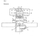
- Fig. 1 is a front view of a door locking device according to the related art
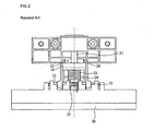
- Fig. 2 is a rear view of the door locking device depicted in Fig. 1 .
- a door locking device of the related art is designed to be installed in a door.
- the door locking device includes a latch body 10 and a latch 20.
- the latch 20 is disposed in the latch body 10 for coupling with a latch lock (not shown) protruded from a front upper portion of a tub.
- the latch 20 includes a latch holder 21 and a latch link 22 connected to a lower end of the latch holder 21.
- the latch holder 21 includes a notched portion 27 at a front for coupling with the latch lock.
- the latch holder 21 and the latch link 22 are connected using a variable hinge 26.
- the variable hinge 26 pivotably connects the latch holder 21 with the latch link 22 and it is a movable hinge.
- a latch spring 23 is fitted around the latch link 22, and the latch link 22 is formed with a latch link hinge 24 at a lower end for coupling with the latch body 10.
- the latch body 10 includes a door wing 15, a latch lock inserting hole 11, and a switch receiving portion 12.
- the door wing 15 is to be fixed to an inside of the door
- the latch lock inserting hole 11 is defined in a center of the door wing 15, and the switch receiving portion 12 is formed at a lower end of the latch body 10.
- the latch body 10 includes an over-rotation preventing board 14 at a rear to prevent the latch holder 21 from over rotation.
- a door handle 30 is connected to a lower rear lower of the latch body 10 via a hinge.
- the latch body 10 defines handle hinge holes 13 at both lower sides, and a handle hinge pin 33 is inserted through the handle hinge holes 13 and knuckle portions of the door handle 30.
- a handle spring 32 is fitted around a middle portion of the handle hinge pin 33, such that the handle 30 can return to its initial position when rotated.
- a door switch 40 is seated on the switch receiving portion 12 formed at the lower end of the latch body 10.
- the door switch 40 includes a contact terminal 41 protruded on a top, and the door handle 30 includes a protruded depressing portion 31 at a front.
- the depressing portion 31 is abutted on the contact terminal 41. Therefore, when a user pulls the door handle 30 to open the door, the door handle 30 is rotated upward and the depressing portion 31 depresses the contact terminal 41 of the door switch 40. Upon the depressing of the contact terminal 41, the opening of the door is detected and a dish-washing operation is terminated.
- the door locking device of the related art is designed such that the top of the door switch 40 is opened to allow the depressing portion 31 to press the contact terminal 41 of the door switch 40.
- a washing water can permeate into the latch body 10 through the latch holder 21, and it can flows down along the inner wall of the latch link 22 or the latch body 10. Therefore, the door switch 40 can be damaged when the washing water drops from the inner wall of the latch link 22 or from the latch body 10 to the opened top of the switch 40.
- the over-rotation preventing board 14 which is formed at the rear of the latch body 10 to prevent the latch holder 21 from over-rotation, makes it hard to install the latch 20 in the latch body 10.
- Documents DE 44 24 201 and US 3 244 830 discloses dishwasher with a door locking device having a latch lock installed at an upper edge of a tub; a latch including a latch holder and a latch link pivotably connected to a lower end of the latch holder, the latch holder being inserted in a door and being formed with a notched portion at a front for coupling with the latch lock; a latch body accommodating the latch, an upper side and/or a lower side of the latch being hinged to the latch body; and at least one detection switch attached to the latch body to detect opening and closing of the door.
- the present invention is directed to a dishwasher and door locking device for the same that substantially obviates one or more problems due to limitations and disadvantages of the related art.
- An object of the present invention is to provide a dishwasher and door locking device for the same, in which a latch and a latch body can be easily assembled, and a washing water is prevented from permeating into a micro switch attached to the latch body to prevent electrical troubles of the micro switch.
- a dishwasher includes: a tub in which a washing chamber is formed; a door opening and closing a front of the tub; a latch lock having a tub insertion portion inserted in an upper edge of the tub and a latch lock ring formed at a front of the tub insertion portion, the latch rock ring defining a hole with a predetermined size; a latch including a latch holder and a latch link pivotably connected to a lower end of the latch holder, the latch holder being inserted in a door and being formed with a notched portion at a front for coupling with the latch lock; a latch body fixed in the door to accommodate the latch; and at least one detection switch attached to the latch body to detect opening and closing of the door, wherein the latch body is formed at a front with a stopper to prevent over rotation of the latch holder.
- a door locking device for a dishwasher includes: a latch lock installed at an upper edge of a tub; a latch including a latch holder and a latch link pivotably connected to a lower end of the latch holder, the latch holder being inserted in a door and being formed with a notched portion at a front for coupling with the latch lock; a latch body accommodating the latch, an upper side and/or a lower side of the latch being hinged to the latch body; and at least one detection switch attached to the latch body to detect opening and closing of the door.
- a door locking device for a dishwasher includes: a latch including a latch holder, a latch link connected to a lower end of the latch holder, and a hinge portion integrally formed at a side of the latch holder and/or the latch link; a latch body having an opened back from which the latch is inserted and a hinge inserting hole at a side for coupling with the hinge portion; at least one detection switch attached to a side of the latch body to detect opening and closing of a door; and a latch lock provided to be hooked by a front portion of the latch holder.
- the latch and the latch body can be assembled through one process, and the micro switch can be protected from water.
- a contact lever is integrally formed with the latch holder, such that a contact detection part of the detection switch can make contact with the contact lever more exactly. Therefore, the opening and closing of the door can be more securely detected.
- Fig. 1 is a front view of a door locking device according to the related art
- Fig. 2 is a rear view of the door locking device depicted in Fig. 1 ;
- Fig. 3 is a schematic section of a dishwasher with a door locking device according to the present invention.
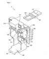
- Fig. 4 is a rear perspective view of a door locking device according to the present invention.
- Fig. 5 is a front view of the door locking device depicted in Fig. 4 ;
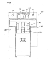
- Fig. 6 is a perspective view showing a connection between a latch and a latch lock of a door locking device according to the present invention.
- Fig. 3 is a schematic section of a dishwasher with a door locking device according to the present invention.
- a door locking device (A) of the present invention is installed between upper portions of a door and a tub of a dishwasher.
- a dishwasher 100 of the present invention includes a tub 110 forming the outside of the dishwasher 100 and defining a washing chamber inside, a door 111 pivotably installed at a front of the tub 110 to open and close the door 111, and a sump 170 installed at a bottom center of the tub 110 to collect a washing water.
- the dishwasher 100 includes a washing pump 180 and a motor 190.
- the washing pump 180 is connected to the sump 170 to pump the washing water of the sump 170 at a high pressure, and the motor 190 is connected to a back of the washing pump 180 to drive it.
- the dishwasher 100 includes a water guide 140 through which the pumped washing water passes, a lower nozzle 160 mounted on the sump 170 to spray the washing water upwardly, an upper nozzle 150 disposed along a middle line of the tub 110 in connection with the water guide 140 to spray the washing water upwardly and/or downwardly, and a top nozzle 155 connected to a terminating end of the water guide 140 to spray the washing water downwardly from a top of the tub 110.
- the dishwasher 100 includes an extendable upper rack 120 and an extendable lower rack 130.
- the upper rack 120 is installed between the upper nozzle 150 and the top nozzle 155 to hold dishes and utensils when the washing water is sprayed from the upper nozzle 150 and/or the top nozzle 155.
- the lower rack 130 is installed between the lower nozzle 160 and the upper nozzle 150 to hold dishes and utensils when the washing water is sprayed from the lower nozzle 160 and/or the upper nozzle 150.
- the upper rack 120 is slidably supported by a rail (not shown) formed on the tub 110, such that the upper rack 120 can be extended and retracted from and into the tub 110.
- the lower rack 130 is formed with rollers that roll along a groove defined at the door 111 when the lower rack 130 is extended from the tub 110.
- a user opens the door 111 and extends the upper rack 120 and/or the lower rack 130 to load dishes or utensils. After loading the dishes or the utensils and closing the door 111, the user inputs washing conditions and presses an operation button to start a washing operation.
- a washing water (detergent-added water) is filled in the sump 170, and the motor 190 drives an impeller (not shown) of the washing pump 180 to pump the washing water from the sump 170 toward the lower nozzle 160 and the water guide 140.
- the washing pump 180 pumps the washing water to the lower nozzle 160 and the water guide 140 in an alternating manner at regular intervals.
- the water pumped to the lower nozzle 160 is sprayed upwardly to the inside of the tub 110, and the washing water pumped to the water guide 140 is sprayed to the inside of tub 110 at the top nozzle 155 and the upper nozzle 150.
- the sprayed washing water washes the dishes and utensils loaded in the upper rack 120 and the lower rack 130.
- the top nozzle 155 sprays the washing water in a downward direction
- the upper nozzle 150 sprays the washing water in an upward direction.
- the lower nozzle 160 sprays the washing water in an upward direction
- the upper nozzle 150 sprays the washing water from its lower spray holes in a downward direction, such that each sides of the dishes and utensils loaded in the lower rack 130 can be washed.
- the contaminated washing water flows back to the sump 170 and passes through a filter (not shown).
- the filtered impurities are discharged by a drain pump (not shown) when the used washing water is discharged from the dishwasher 100.
- pure water is filled in the sump 170 through a water inlet and it is sprayed through the upper nozzle 150 and the lower nozzle 160 in the same way as described above.
- the sprayed pure water rinses the dishes and utensils and then it is discharged from the dishwasher 100.
- a hot air is supplied to the inside of the tub to dry the dishes and utensils. That is, the dishes and utensils are cleaned through the washing, rinsing, and drying processes of the dishwasher 100.
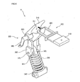
- Fig. 4 is a rear perspective view of a door locking device according to the present invention
- Fig. 5 is a front view of the door locking device depicted in Fig. 4 .
- the door locking device (A) of the present invention includes a latch body 200, a latch 300, and a latch lock 400.
- the latch body encloses inner parts and it is installed in the door 111.
- the latch 300 is hinged on the inside of the latch body 200 to lock the door 111 when the door 111 closes the tub 110, and the latch lock 400 is fixedly inserted in an upper edge of the tub 110 for coupling with the latch 300.
- the latch lock 400 includes a tub insertion portion 410 and a latch lock ring 420 extended forwardly from the tub insertion portion 410. When assembled, the tub insertion portion 410 is inserted into the upper edge of the tub 110, and the latch lock ring 420 is protruded from the tub 110.
- the latch 300 includes a latch holder (refer to 310 in Fig. 6 ) and a latch link (refer to 320 in Fig. 6 ).
- the latch holder 310 is fitted into the latch lock ring 420 when the door 111 is closed, and the latch link 320 is pivotably connected to a lower end of the latch holder 310.
- the latch 300 will be described later in detail with reference to Fig. 6 .
- the latch body 200 defines an accommodation space to receive the latch 300. Also, the latch body 200 is formed with a latch holder receiving portion 210 to receive the latch holder 310. At both sides of the latch holder receiving portion 210, fastener holes 211 are defined to fix the latch body 200 to the inside of the door by using fasteners such as screws.
- the latch body 200 defines hinge inserting holes 270 under the fastener holes 211 for coupling with latch holder hinges (refer to 350 in Fig. 6 ). Further, the latch body 200 includes a handle mounting portion 260 at a lower end and latch link hinge holes 250 at both sides. A handle (not shown) is to be mounted on the handle mounting portion 260 for a user to grip it.
- a micro switch 500 is attached to each side of the latch body 200 to detect opening and closing of the door 111. Also, a switch cover 220 is formed at a front of the latch body 200 to prevent a washing water from permeating into the switch cover 220.
- the latch body 200 includes protruded support ribs 240 to support a front and a back of the micro switch 500. Also, the latch body 200 includes fixing protrusions 241 projected from a side to support the micro switch 500.
- the micro switch 500 defines protrusion inserting holes 530 at corners for coupling with the fixing protrusions 241. Also, the micro switch 500 includes a contact detection part such as contact terminal 510 at a back and a wire connecting terminal 520 at a bottom and/or a side.
- the contact terminal 510 is protrusively formed to detect opening and closing of the door 111. The contact terminal 510 is depressed by a contact lever (refer to 360 in Fig. 6 ) formed at an end of the latch holder hinge 350.
- the latch body 200 defines a ring inserting hole 212 at a front of the latch holder receiving portion 210 to receive the latch lock ring 420 of the latch lock 400. Further, the latch body 200 is formed with a latch holder supporting portion 230 that is stepped under the ring inserting hole 212.
- the latch holder supporting portion 230 prevents the latch holder 310 from being rotated too much by the latch lock ring 420 when the door 111 is opened.
- the switch cover 220 is integrally formed with the latch holder supporting portion 230.
- the switch cover 220 is horizontally extended from the latch holder supporting portion 230 by a predetermined length and then it is bent to lengthily extend in a downward direction. That is, the switch cover 220 covers a top and a front of the micro switch 500. Therefore, a washing water permeated through the ring inserting hole 212 is prevented from flowing into the micro switch 500.
- Fig. 6 is a perspective view showing a connection between a latch and a latch lock of a door locking device according to the present invention.
- the latch 300 of the present invention includes the latch holder 310 and the latch link 320 connected to the lower end of the latch holder 310.
- the latch holder 310 has a notched portion 311 with a predetermined depth at an upper end for coupling with the latch lock ring 420. Also, the latch holder 310 includes a latch holder hinge 350 that is protruded from each side in a horizontal direction for coupling with the hinge inserting holes 270 of the latch body 200. The contact lever 360 is downwardly extended from the end of the latch holder hinge 350 to depress the contact terminal 510 of the micro switch 500. Further, the latch holder 310 includes latch holder legs 380 that are symmetrically extended in a downward direction. Between the latch holder legs 380, the upper end of the latch link 320 is pivotably inserted using a variable hinge 370.
- the upper end of the latch link 320 has a flat shape. That is, the width of the flat portion of the latch link 320 is smaller than the width of the gap between the latch holder legs 380.
- the length of the flat portion is about one half of the total length of the latch link 320.
- the latch link 320 defines a variable hinge slot 321 at the flat portion.
- the variable hinge 370 is inserted through the variable hinge slot 321 and its both ends are inserted hinge holes defined in the latch holder legs 380. That is, the latch holder 310 and the latch link 320 are connected by the variable hinge 370.
- variable hinge slot 321 is extended in a length direction of the latch link 320, such that the variable hinge 370 can move up and down when the door 111 is opened and closed.
- a latch spring 330 with a predetermined elasticity is fitted around the latch link 320, and a latch link hinge 340 is formed at a lower end of the latch link 320.
- the latch link hinge 340 is extended in a perpendicular direction to the length direction of the latch link 320.
- the latch holder hinge 350 of the latch 300 is inserted into the hinge inserting holes 270 of the latch body 200, and then the latch 300 is pushed toward the accommodation space formed in the latch body 200 to insert the latch 300 in the latch body 200.
- the latch link hinge 340 is inserted in the latch link hinge holes 250 defined in both the lower sides of the latch body 200.
- the latch 300 is pivotably fixed to the latch body 200 at the latch holder hinge 350 and the latch link hinge 340.
- the variable hinge 370 reciprocates in the variable hinge slot 321 when the door 111 is opened and closed.
- the latch body 200 is characterized in that the back of the latch body 200 is opened to easily receive the latch 300. That is, the latch body 200 does not require the over-rotation preventing board that is employed in the related art, such that the latch 300 can be easily assembled into the latch body 200.
- the latch holder hinge 350 is directly inserted into the hinge inserting holes 270 of the latch body 200 without using a hinge pin that is required in the related art, thereby removing the inconvenience of using the hinge pin.
- the switch cover 220 is extended from the upper front of the latch body 200 as one piece to cover the top and front of the micro switch 500, such that the washing water can be prevented from permeating through the micro switch 500.
- the contact lever 360 is integrally formed with the latch holder hinge 350 to depress the contact terminal 510 formed at the back of the micro switch 500, such that the opening and closing of the door 111 can be exactly detected.
- the contact lever 360 is rotated together with the latch holder 310 when the door 111 is opened and closed, such that the depressing and releasing actions of the contact lever 360 can be exactly carried out.
Landscapes
- Engineering & Computer Science (AREA)
- Mechanical Engineering (AREA)
- Health & Medical Sciences (AREA)
- General Health & Medical Sciences (AREA)
- Toxicology (AREA)
- Life Sciences & Earth Sciences (AREA)
- Environmental Sciences (AREA)
- Washing And Drying Of Tableware (AREA)
Claims (14)
- Türverriegelungsvorrichtung für einen Geschirrspüler, umfassend:ein Fallenschloss (400), das an einem oberen Rand eines Spülbehälters (110) installiert ist;einen Fallenriegel (300), der einen Fallenriegelhalter (310) und ein Fallenriegelglied (320), das schwenkbar mit einem unteren Ende des Fallenriegelhalters (310) verbunden ist, enthält, wobei der Fallenriegelhalter (310) in einer Tür (111) eingesetzt und mit einem gekerbten Abschnitt (311) an einer Vorderseite zur Kopplung mit dem Fallenschloss (400) ausgebildet ist;einen Fallenriegelkörper (200), der den Fallenriegel (300) aufnimmt, wobei eine Oberseite und/oder eine Unterseite des Fallenriegels (300) über ein Scharnier mit dem Fallenriegelkörper (200) verbunden ist; undmindestens einen Erfassungsschalter (500), der an dem Fallenriegelkörper (200) zur Erfassung des Öffnens und Schließens der Tür (111) befestigt ist,dadurch gekennzeichnet, dass der Fallenriegelkörper (200) an einer Vorderseite mit einem Anschlag (230) ausgebildet ist, um ein Überdrehen des Fallenriegelhalters (310) zu verhindern.
- Türverriegelungsvorrichtung nach Anspruch 1, wobei der Fallenriegelhalter ein Fallenriegelhalterscharnier (350) enthält, wobei sich das Fallenriegelhalterscharnier über eine vorbestimmte Länge von einer Seite des Fallenriegelhalters und/oder jeder Seite des Fallenriegelhalters erstreckt und drehbar in dem Fallenriegelkörper eingesetzt ist.
- Türverriegelungsvorrichtung nach Anspruch 2, wobei das Fallenriegelhalterscharnier integral mit dem Fallenriegelhalter ausgebildet ist.
- Türverriegelungsvorrichtung nach Anspruch 2, wobei der Fallenriegelkörper ein Scharniereinsetzloch (270) an mindestens einer Seite definiert, um das Fallenriegelhalterscharnier drehbar aufzunehmen.
- Türverriegelungsvorrichtung nach Anspruch 1, wobei der Fallenriegelhalter einen Kontakthebel (360) enthält, der sich von einer Seite und/oder jeder Seite mit einer vorbestimmten Länge erstreckt und gebogen ist, um den Erfassungsschalter zu berühren.
- Türverriegelungsvorrichtung nach Anspruch 5, wobei der Erfassungsschalter an einer Seite mit einem Kontaktanschluss (410) zur Herstellung von Kontakt mit dem Kontakthebel ausgebildet ist.
- Türverriegelungsvorrichtung nach Anspruch 1, wobei der Fallenriegelkörper eine Schalterabdeckung (220) enthält, um zu verhindern, dass Wasser in den Erfassungsschalter eindringt.
- Türverriegelungsvorrichtung nach Anspruch 7, wobei die Schalterabdeckung eine Oberseite und/oder eine Vorderseite des Erfassungsschalters abdeckt.
- Türverriegelungsvorrichtung nach Anspruch 1, wobei der Fallenriegelkörper an einer Rückseite geöffnet ist, um den Fallenriegel aufzunehmen.
- Türverriegelungsvorrichtung nach Anspruch 1, wobei der Fallenriegelkörper mindestens eine Stützrippe (240) an mindestens einer Seite enthält, um den Erfassungsschalter fest zu halten.
- Türverriegelungsvorrichtung nach Anspruch 10, wobei sich die Stützrippen gegenüber einander befinden.
- Türverriegelungsvorrichtung nach Anspruch 1, wobei der Fallenriegelkörper mindestens einen Befestigungsvorsprung (241) an mindestens einer Seite zur Befestigung des Erfassungsschalters enthält und der Erfassungsschalter mindestens ein Loch (530) definiert, in dem der Befestigungsvorsprung eingesetzt ist.
- Türverriegelungsvorrichtung nach Anspruch 1, wobei der Fallenriegelkörper an einer Vorderseite mit einem Loch (212) zum Anbringen oder Loslösen eines Fallenriegelrings (420) des Fallenriegelschlosses ausgebildet ist.
- Geschirrspüler, der eine Türverriegelungsvorrichtung nach einem der vorhergehenden Ansprüche umfasst.
Applications Claiming Priority (2)
| Application Number | Priority Date | Filing Date | Title |
|---|---|---|---|
| KR2004035896 | 2004-05-20 | ||
| KR1020040035896A KR101054134B1 (ko) | 2004-05-20 | 2004-05-20 | 식기 세척기의 도어 잠금장치 |
Publications (3)
| Publication Number | Publication Date |
|---|---|
| EP1597997A2 EP1597997A2 (de) | 2005-11-23 |
| EP1597997A3 EP1597997A3 (de) | 2007-08-29 |
| EP1597997B1 true EP1597997B1 (de) | 2012-10-17 |
Family
ID=34942319
Family Applications (1)
| Application Number | Title | Priority Date | Filing Date |
|---|---|---|---|
| EP05291083A Ceased EP1597997B1 (de) | 2004-05-20 | 2005-05-19 | Geschirrspülmaschine und Verriegelungsvorrichtung dazu |
Country Status (3)
| Country | Link |
|---|---|
| US (1) | US7552738B2 (de) |
| EP (1) | EP1597997B1 (de) |
| KR (1) | KR101054134B1 (de) |
Families Citing this family (7)
| Publication number | Priority date | Publication date | Assignee | Title |
|---|---|---|---|---|
| KR101294777B1 (ko) * | 2006-02-13 | 2013-08-08 | 엘지전자 주식회사 | 식기세척기의 도어 개폐장치 |
| US8347902B2 (en) * | 2010-02-10 | 2013-01-08 | Whirlpool Corporation | Lever handle mechanism for a dishwasher |
| KR20140035413A (ko) * | 2011-05-19 | 2014-03-21 | 에코랍 인코퍼레이티드 | 기계식 식기세척을 위한 세정 방법 |
| US9267315B2 (en) * | 2013-03-18 | 2016-02-23 | Poong Won Industry Co., Ltd. | Door safety locking apparatus |
| WO2014161793A1 (en) * | 2013-04-05 | 2014-10-09 | Arcelik Anonim Sirketi | A household appliance comprising a lock |
| CN104337487B (zh) * | 2013-07-31 | 2018-11-09 | 伊利诺斯工具制品有限公司 | 门锁和安装有门锁的洗碗机 |
| DE102020120817A1 (de) * | 2020-08-06 | 2022-02-10 | Pilz Gmbh & Co. Kg | Schutztürüberwachungsmodul |
Family Cites Families (21)
| Publication number | Priority date | Publication date | Assignee | Title |
|---|---|---|---|---|
| US3024074A (en) * | 1958-07-18 | 1962-03-06 | Gen Motors Corp | Domestic appliance |
| US3244830A (en) * | 1963-08-19 | 1966-04-05 | Nat Lock Co | Latching mechanism for front opening cabinets |
| US3328062A (en) * | 1965-07-26 | 1967-06-27 | Hobart Mfg Co | Latch mechanism |
| US3323822A (en) * | 1965-12-01 | 1967-06-06 | Design & Mfg Corp | Latch |
| US3415961A (en) * | 1966-09-26 | 1968-12-10 | Whirlpool Co | Latch mechanism |
| US3854762A (en) * | 1973-08-02 | 1974-12-17 | Whirlpool Co | Rotary handle door latch for dishwashers |
| DE2826712C2 (de) | 1978-06-19 | 1983-01-05 | Bosch-Siemens Hausgeräte GmbH, 7000 Stuttgart | Verschlußvorrichtung für die Tür von elektrischen Haushaltgeräten |
| KR890008084Y1 (ko) * | 1986-12-30 | 1989-11-20 | 삼성전자 주식회사 | 식기 세척기의 도어 잠금 장치 |
| IT229049Y1 (it) * | 1992-07-23 | 1998-06-24 | Zanussi Elettrodomestici | Mobile, in particolare per elettrodomestico, con porta di chiusura |
| US5440103A (en) * | 1994-05-27 | 1995-08-08 | Robertshaw Controls Company | Cooking apparatus, latching construction therefor and methods of making the same |
| DE4424201C2 (de) * | 1994-07-09 | 1996-05-09 | Ymos Ag Ind Produkte | Schließvorrichtung, insbesondere für die Tür einer Spülmaschine |
| DE19504797C2 (de) | 1995-02-14 | 1997-04-24 | Ymos Ag Ind Produkte | Schließvorrichtung für die Tür einer Spülmaschine |
| DE19601229C2 (de) * | 1996-01-15 | 1998-02-12 | Zangenstein Elektro | Türschloß für wasserbrauchende Wasch- oder Spülmaschinen |
| KR19980057010U (ko) * | 1997-01-28 | 1998-10-15 | 구자홍 | 식기 세척기의 도어 개방장치 |
| JP3962446B2 (ja) | 1997-03-17 | 2007-08-22 | ホシザキ電機株式会社 | 食器洗浄機のラック支持構造 |
| US6155616A (en) * | 1997-06-16 | 2000-12-05 | Randall C. Hansen | Locking mechanism and closure assembly including same |
| IT243440Y1 (it) | 1997-11-03 | 2002-03-04 | Gaetano Pagano | Dispositivo di bloccaggio per porta di apparecchio domestico,per esempio lavastoviglie |
| KR19990023287U (ko) * | 1997-12-04 | 1999-07-05 | 구자홍 | 식기세척기의 도어 개폐장치 |
| US6390518B1 (en) * | 2000-08-15 | 2002-05-21 | Maytag Corporation | Latching mechanism for an appliance door |
| DE50014457D1 (de) * | 2000-12-01 | 2007-08-16 | Emz Hanauer Gmbh & Co Kgaa | Türverriegelung |
| US7306266B2 (en) * | 2004-03-05 | 2007-12-11 | Illinois Tool Works, Inc. | Appliance latch having a rotating latch hook mounted on a linear slide |
-
2004
- 2004-05-20 KR KR1020040035896A patent/KR101054134B1/ko not_active Expired - Fee Related
-
2005
- 2005-05-19 US US11/132,346 patent/US7552738B2/en not_active Expired - Fee Related
- 2005-05-19 EP EP05291083A patent/EP1597997B1/de not_active Ceased
Also Published As
| Publication number | Publication date |
|---|---|
| US20050257813A1 (en) | 2005-11-24 |
| KR20050110927A (ko) | 2005-11-24 |
| EP1597997A3 (de) | 2007-08-29 |
| EP1597997A2 (de) | 2005-11-23 |
| KR101054134B1 (ko) | 2011-08-03 |
| US7552738B2 (en) | 2009-06-30 |
Similar Documents
| Publication | Publication Date | Title |
|---|---|---|
| US7493905B2 (en) | Dishwasher | |
| KR101054117B1 (ko) | 워터 가이드 탈거 방지구조가 구비된 식기 세척기 | |
| WO2006028324A1 (en) | A nozzle structure of dish washer | |
| EP1597997B1 (de) | Geschirrspülmaschine und Verriegelungsvorrichtung dazu | |
| US20050285412A1 (en) | Dishwasher and door locking device for the same | |
| CA2442292C (en) | Dishwasher | |
| KR100892672B1 (ko) | 식기 세척기용 디스펜서 | |
| KR20200124976A (ko) | 식기세척기 | |
| CN217610950U (zh) | 一种洗碗机 | |
| EP2371256A2 (de) | Geschirrspüler | |
| JP3546809B2 (ja) | 食器洗浄機 | |
| JP4470340B2 (ja) | 食器洗い機 | |
| KR101070104B1 (ko) | 식기 세척기의 도어 잠금장치 | |
| KR20170137520A (ko) | 도어 잠금장치 및 이를 이용한 식기 세척기 | |
| JP2001070218A (ja) | 食器洗浄機 | |
| KR100662156B1 (ko) | 식기 세척기의 워터 가이드 결합 구조 | |
| KR101054105B1 (ko) | 식기 세척기의 도어 개폐구조 | |
| JP3540559B2 (ja) | 洗浄機 | |
| KR20070078131A (ko) | 식기 세척기의 도어 개폐 장치 | |
| KR101054144B1 (ko) | 식기 세척기의 도어 로킹구조 | |
| JP2006263174A (ja) | 食器洗浄機および扉の開閉検知装置 | |
| CN111050620B (zh) | 洗碗机 | |
| KR101127987B1 (ko) | 식기세척기의 세척수 튐 방지장치 | |
| KR101178693B1 (ko) | 식기 세척기 | |
| JP2004000790A (ja) | 食器洗浄機 |
Legal Events
| Date | Code | Title | Description |
|---|---|---|---|
| PUAI | Public reference made under article 153(3) epc to a published international application that has entered the european phase |
Free format text: ORIGINAL CODE: 0009012 |
|
| AK | Designated contracting states |
Kind code of ref document: A2 Designated state(s): AT BE BG CH CY CZ DE DK EE ES FI FR GB GR HU IE IS IT LI LT LU MC NL PL PT RO SE SI SK TR |
|
| AX | Request for extension of the european patent |
Extension state: AL BA HR LV MK YU |
|
| PUAL | Search report despatched |
Free format text: ORIGINAL CODE: 0009013 |
|
| AK | Designated contracting states |
Kind code of ref document: A3 Designated state(s): AT BE BG CH CY CZ DE DK EE ES FI FR GB GR HU IE IS IT LI LT LU MC NL PL PT RO SE SI SK TR |
|
| AX | Request for extension of the european patent |
Extension state: AL BA HR LV MK YU |
|
| RIC1 | Information provided on ipc code assigned before grant |
Ipc: E05C 3/24 20060101ALI20070724BHEP Ipc: A47L 15/42 20060101AFI20050907BHEP |
|
| 17P | Request for examination filed |
Effective date: 20080221 |
|
| AKX | Designation fees paid |
Designated state(s): DE |
|
| 17Q | First examination report despatched |
Effective date: 20111220 |
|
| GRAP | Despatch of communication of intention to grant a patent |
Free format text: ORIGINAL CODE: EPIDOSNIGR1 |
|
| GRAS | Grant fee paid |
Free format text: ORIGINAL CODE: EPIDOSNIGR3 |
|
| GRAA | (expected) grant |
Free format text: ORIGINAL CODE: 0009210 |
|
| AK | Designated contracting states |
Kind code of ref document: B1 Designated state(s): DE |
|
| REG | Reference to a national code |
Ref country code: DE Ref legal event code: R096 Ref document number: 602005036557 Country of ref document: DE Effective date: 20121213 |
|
| PLBE | No opposition filed within time limit |
Free format text: ORIGINAL CODE: 0009261 |
|
| STAA | Information on the status of an ep patent application or granted ep patent |
Free format text: STATUS: NO OPPOSITION FILED WITHIN TIME LIMIT |
|
| 26N | No opposition filed |
Effective date: 20130718 |
|
| REG | Reference to a national code |
Ref country code: DE Ref legal event code: R097 Ref document number: 602005036557 Country of ref document: DE Effective date: 20130718 |
|
| PGFP | Annual fee paid to national office [announced via postgrant information from national office to epo] |
Ref country code: DE Payment date: 20190405 Year of fee payment: 15 |
|
| REG | Reference to a national code |
Ref country code: DE Ref legal event code: R119 Ref document number: 602005036557 Country of ref document: DE |
|
| PG25 | Lapsed in a contracting state [announced via postgrant information from national office to epo] |
Ref country code: DE Free format text: LAPSE BECAUSE OF NON-PAYMENT OF DUE FEES Effective date: 20201201 |