EP1597461B1 - Kühlkreislauf für einen personenkraftwagen und der entsprechende personenkraftwagen - Google Patents
Kühlkreislauf für einen personenkraftwagen und der entsprechende personenkraftwagen Download PDFInfo
- Publication number
- EP1597461B1 EP1597461B1 EP04715351A EP04715351A EP1597461B1 EP 1597461 B1 EP1597461 B1 EP 1597461B1 EP 04715351 A EP04715351 A EP 04715351A EP 04715351 A EP04715351 A EP 04715351A EP 1597461 B1 EP1597461 B1 EP 1597461B1
- Authority
- EP
- European Patent Office
- Prior art keywords
- orifice
- valve
- circuit according
- stopper
- escape
- Prior art date
- Legal status (The legal status is an assumption and is not a legal conclusion. Google has not performed a legal analysis and makes no representation as to the accuracy of the status listed.)
- Expired - Lifetime
Links
- 238000001816 cooling Methods 0.000 title claims description 40
- 239000012809 cooling fluid Substances 0.000 claims description 6
- 238000002485 combustion reaction Methods 0.000 claims description 4
- 238000007789 sealing Methods 0.000 claims description 2
- 208000031968 Cadaver Diseases 0.000 description 6
- 239000002826 coolant Substances 0.000 description 6
- 239000012530 fluid Substances 0.000 description 5
- 239000007788 liquid Substances 0.000 description 3
- 230000002093 peripheral effect Effects 0.000 description 3
- 230000000694 effects Effects 0.000 description 2
- 238000002955 isolation Methods 0.000 description 2
- 235000005921 Cynara humilis Nutrition 0.000 description 1
- 240000002228 Cynara humilis Species 0.000 description 1
- 241000920340 Pion Species 0.000 description 1
- 230000003213 activating effect Effects 0.000 description 1
- 238000004891 communication Methods 0.000 description 1
- 230000000295 complement effect Effects 0.000 description 1
- 230000005484 gravity Effects 0.000 description 1
- 238000013021 overheating Methods 0.000 description 1
- 239000013589 supplement Substances 0.000 description 1
- 238000013022 venting Methods 0.000 description 1
- XLYOFNOQVPJJNP-UHFFFAOYSA-N water Substances O XLYOFNOQVPJJNP-UHFFFAOYSA-N 0.000 description 1
Images

Classifications
-
- F—MECHANICAL ENGINEERING; LIGHTING; HEATING; WEAPONS; BLASTING
- F01—MACHINES OR ENGINES IN GENERAL; ENGINE PLANTS IN GENERAL; STEAM ENGINES
- F01P—COOLING OF MACHINES OR ENGINES IN GENERAL; COOLING OF INTERNAL-COMBUSTION ENGINES
- F01P11/00—Component parts, details, or accessories not provided for in, or of interest apart from, groups F01P1/00 - F01P9/00
- F01P11/02—Liquid-coolant filling, overflow, venting, or draining devices
- F01P11/029—Expansion reservoirs
-
- F—MECHANICAL ENGINEERING; LIGHTING; HEATING; WEAPONS; BLASTING
- F01—MACHINES OR ENGINES IN GENERAL; ENGINE PLANTS IN GENERAL; STEAM ENGINES
- F01P—COOLING OF MACHINES OR ENGINES IN GENERAL; COOLING OF INTERNAL-COMBUSTION ENGINES
- F01P11/00—Component parts, details, or accessories not provided for in, or of interest apart from, groups F01P1/00 - F01P9/00
- F01P11/02—Liquid-coolant filling, overflow, venting, or draining devices
- F01P11/0204—Filling
- F01P11/0209—Closure caps
- F01P11/0247—Safety; Locking against opening
-
- F—MECHANICAL ENGINEERING; LIGHTING; HEATING; WEAPONS; BLASTING
- F01—MACHINES OR ENGINES IN GENERAL; ENGINE PLANTS IN GENERAL; STEAM ENGINES
- F01P—COOLING OF MACHINES OR ENGINES IN GENERAL; COOLING OF INTERNAL-COMBUSTION ENGINES
- F01P11/00—Component parts, details, or accessories not provided for in, or of interest apart from, groups F01P1/00 - F01P9/00
- F01P11/02—Liquid-coolant filling, overflow, venting, or draining devices
- F01P11/0204—Filling
- F01P11/0209—Closure caps
- F01P11/0238—Closure caps with overpressure valves or vent valves
-
- F—MECHANICAL ENGINEERING; LIGHTING; HEATING; WEAPONS; BLASTING
- F01—MACHINES OR ENGINES IN GENERAL; ENGINE PLANTS IN GENERAL; STEAM ENGINES
- F01P—COOLING OF MACHINES OR ENGINES IN GENERAL; COOLING OF INTERNAL-COMBUSTION ENGINES
- F01P11/00—Component parts, details, or accessories not provided for in, or of interest apart from, groups F01P1/00 - F01P9/00
- F01P11/02—Liquid-coolant filling, overflow, venting, or draining devices
- F01P11/0204—Filling
- F01P11/0209—Closure caps
- F01P11/0247—Safety; Locking against opening
- F01P2011/0266—Safety; Locking against opening activated by pressure
Definitions
- the present invention relates to a cooling system for a motor vehicle, and a motor vehicle provided with such a cooling circuit.
- a cooling circuit comprises various pipes, also called hoses, which extend in the vicinity of the engine and the radiator of the motor vehicle. There is further provided a member for selectively accessing the interior volume of this circuit, so that a user can periodically proceed with a makeup of coolant.
- the aforementioned member in the form of a plug, which is movable between respective positions of closure and access to this interior volume.
- the cap is fixed on the body of the cooling circuit, for example by screwing or by means of a quick fixing, type "quarter turn".
- This cap is further provided with a valve allowing the escape of air and water, out of the cooling circuit, when the coolant pressure reaches an abnormally high value, especially in case of overheating. It also has an additional valve, allowing the admission of air, by depression, in the cooling circuit.
- Such a plug is known from document SU 1178916A.
- the invention proposes to provide a cooling circuit to overcome the various disadvantages of the prior art mentioned above.
- a cooling circuit for a motor vehicle in particular for a motor vehicle with internal combustion, comprising a body comprising at least one pipe intended to extend in the vicinity of the engine and the radiator of said vehicle, this body having an internal volume for receiving a cooling fluid, this circuit also comprising a plug selectively closing an access orifice to this interior volume, this cap being removably attached to the body, and means ensuring the escape of said cooling fluid, especially in the event of overpressure, via an exhaust port, characterized in that the respective exhaust and access ports to the internal volume are distinct and in that there is provided a valve, removably attached to the plug, this valve being movable, when it is disengaged with respect to the plug, between respective positions s shutter and release of the access port, the valve being able to leave its closed position only when the pressure in the interior volume becomes less than a predetermined pressure.
- the invention also relates to a motor vehicle, in particular an internal combustion engine, which is provided with a cooling circuit as defined above.
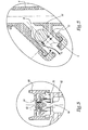
- the cooling circuit conventionally comprises several pipes, or hoses, of which only one is shown on this Figure 1, where it is assigned the reference 2. These different hoses extend, in a usual manner, in the vicinity of the engine and the radiator of a motor vehicle, which are not shown.
- a connector 4 coaxial with the hose 2 is stitched at the end of the latter. It is hollowed out with a lateral orifice 6, intended for the escape of the fluid admitted into the cooling circuit, as will be seen later.
- This orifice 6 opens into a housing 8, within which is received a valve 10, able to selectively close the orifice 6 above.
- This valve is mounted against a spring 12, supported by one of its ends against a plug 14, which is hollowed with an opening 16 for communicating the housing 8 with the atmosphere.
- the housing 8 extends obliquely, generally downwards. In this way, as will be seen more precisely in what follows, this makes it possible to give a descending direction to the fluid possibly escaping from the cooling circuit.
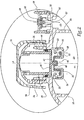
- the hose 2 is connected to an expansion vessel 18, of a type known per se, which has a vertical main axis, denoted A.
- This vessel 18 is divided, in its upper part, into a main chamber 20 and a peripheral chamber 22 which are separated by a vertical annular wall 24.
- the expansion vessel 18 is provided with a threaded neck 26.
- a reentrant peripheral flange 28 defining an orifice 30. allowing access to the interior volume V of the expansion tank.
- the expansion vessel 18 is further capped with a cap, generally designated by the reference 32.
- the latter comprises a threaded body 34, intended to cooperate with the threaded neck 26, and an outer shell 36, ensuring the grip by a user.
- the body 34 and the shell 36 are such that they confer a disengageable character to the screwing of the cap 32 on the neck 26. This means that, prior to the rotational movement allowing the cap to be unscrewed, the user must proceed with a complementary movement in this case press down on the shell 36.
- This disengageable nature may, however, be provided in a different manner, in particular by providing that the user must pinch the shell 36 against the body 34, before proceeding to the aforementioned unscrewing.
- the plug 32 is provided with a skirt 38, having a closed bottom 40, which is provided with a pin 42, whose function will be explained in the following.
- An O-ring 44 is moreover imprisoned between the facing faces of the neck 26 and the skirt 38.
- valve 46 having a core 48, extended by a side wall 50, which is itself terminated by an outer flange 52.
- This valve 46 is removably attached to the plug 32, by any appropriate means, the occurrence by resilient snapping of the core 48 on the pin 42.
- the side wall 50 and the flange 52 of the valve 46 are received in a housing 54, defined by an annular piece 56, which is fixed on the body of the expansion vessel, in the vicinity of the flange 28.
- This annular piece 56 is hollowed out of a light 58, for communicating the internal volume V with the access port 30.
- the peripheral chamber 22 is placed in communication, at its upper end, with an opening 60, defined by a recessed rim 62. Above the latter is provided a plug 64, hollowed out with an orifice 66, intended for the putting the interior volume V at atmospheric pressure, as will be seen later.
- This cap is equipped with a valve 68, which selectively closes the orifice 66.
- the latter is mounted against a spring 70, one end of which bears against the aforementioned flange 62.
- FIGS 1 and 2 illustrate the cooling circuit in a normal operating state.
- the valve 10 closes the exhaust port 6, while the valve 68 closes the atmospheric pressure port 66 and the main cap 32 is screwed onto the neck 26.
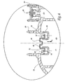
- valve 68 When the internal volume V of the expansion vessel 18 is at a pressure much lower than the atmospheric pressure, the valve 68 tends to move away from its seat, formed on the plug 64. This then releases the orifice 66, of so that outside air can penetrate towards the interior volume V, according to the arrows F 1 in Figure 3, which induces an increase in the internal pressure of the cooling circuit.
- valve 68 can also allow the filling of the cooling circuit by a professional, via the orifice 66. This is advantageous, in terms of simplicity and speed, for the manufacturer who can fill the circuit cooling without removing the plug 32.
- valve 46 which now occupies a position of release from the orifice 30, rests against the annular piece 56.
- the predetermined pressure value, below which the valve 46 leaves its closed position of the orifice 30, may be different from that mentioned above. It is thus possible to provide means, for example resilient, opposing the movement of this valve in one or the other direction.
- valve 10 is pushed away from its seat, which releases the exhaust port 6. Therefore, the superheated liquid is expelled of the cooling circuit via this orifice.
- this liquid is located downward, for example towards the ground, along the arrow F 3 in Figure 5. In this way, this phenomenon is not likely to affect the physical integrity of the driver.
- the invention is not limited to the example described and shown.
- valve 68 of atmospheric pressure can in particular be integrated in the plug 32.
- valve 10 may for example be provided on the body of the expansion vessel 18.
- the invention makes it possible to achieve the objectives mentioned above.
- the respective exhaust and access ports to the interior volume are distinct. This allows to close the access port by means of a plug, which is able to present a first degree of security for the user. Furthermore, it is possible to arrange the exhaust port, so that the fluid possibly expelled from the cooling circuit is not directed towards the user.
- valve 46 which allows access to the internal volume only when the pressure drops below a threshold value, provides an additional degree of safety to the cooling circuit of the invention. Indeed, thanks to this measure, the user can not make a refill of coolant, when the internal pressure is likely to affect his physical integrity.
- main plug 32 provided with a threaded body, can be adapted to existing cooling circuits. This is particularly advantageous, especially in economic terms.
Landscapes
- Engineering & Computer Science (AREA)
- Chemical & Material Sciences (AREA)
- Combustion & Propulsion (AREA)
- Mechanical Engineering (AREA)
- General Engineering & Computer Science (AREA)
- Cooling, Air Intake And Gas Exhaust, And Fuel Tank Arrangements In Propulsion Units (AREA)
- Quick-Acting Or Multi-Walled Pipe Joints (AREA)
- Motor Or Generator Cooling System (AREA)
- Closures For Containers (AREA)
- Devices That Are Associated With Refrigeration Equipment (AREA)
Claims (13)
- Kühlkreislauf für ein Kraftfahrzeug, insbesondere für ein Kraftfahrzeug mit innerer Verbrennung, umfassend einen Körper, welcher mindestens eine Leitung (2) aufweist, die dazu vorgesehen ist, sich in die Nähe des Motors und des Kühlers des besagten Fahrzeugs zu erstrecken, wobei dieser Körper einen Innenraum (V) zur Aufnahme eines Kühlmediums besitzt, wobei dieser Kreislauf ebenfalls einen Stopfen (32) zum wahlweisen Verschließen einer Zugangsöffnung (30) zu diesem Innenraum (V) umfasst, wobei dieser Stopfen abnehmbar am Körper befestigt ist, sowie Mittel (10), welche über eine Entweichöffnung (6) das Entweichen des besagten Kühlmediums insbesondere bei Überdruck gewährleisten, wobei die Entweichöffnung (6) und die Zugangsöffnung (30) zum Innenraum voneinander verschieden sind, dadurch gekennzeichnet, dass eine Klappe (46) vorgesehen ist, welche abnehmbar am Stopfen (32) befestigt ist, wobei diese Klappe, wenn sie vom Stopfen getrennt ist, zwischen einer Verschließstellung bzw. einer Freigabestellung der Zugangsöffnung (30) beweglich ist, wobei diese Klappe ihre Verschließstellung nur dann verlassen kann, wenn der im Innenraum (V) herrschende Druck unter einen vorbestimmten Druck absinkt.
- Kreislauf nach Anspruch 1, dadurch gekennzeichnet, dass der vorbestimmte Druck dem Luftdruck nahe kommt, insbesondere dass er leicht höher ist als dieser.
- Kreislauf nach Anspruch 1 oder 2, dadurch gekennzeichnet, dass der Körper des Kühlkreislaufs Mittel (56) zum Stützen der Klappe (46) in ihrer Freigabestellung umfasst.
- Kreislauf nach einem der vorangegangenen Ansprüche, dadurch gekennzeichnet, dass der Körper des Kühlkreislaufs Anschlagmittel (28) umfasst, die in der Lage sind, einer Translationsbewegung der Klappe (46), insbesondere nach oben, derart entgegenzuwirken, dass diese Klappe vom Stopfen (32) getrennt wird.
- Kreislauf nach einem der vorangegangenen Ansprüche, dadurch gekennzeichnet, dass der Stopfen einen insbesondere durch Verschrauben an den Körper des Kühlkreislaufs anbringbaren Körper (34) sowie eine vom Körper (34) des Stopfens lösbare Greifschale (36) zum Greifen durch einen Nutzer aufweist.
- Kreislauf nach einem der vorangegangenen Ansprüche, dadurch gekennzeichnet, dass der Stopfen (32) mit einem Mantel (38) versehen ist, welcher in das Innere eines Halses (26) des Kühlkreislaufs einbringbar ist, wobei auf der diesem Mantel und diesem Hals gegenüberliegenden Seite Dichtungsmittel (34) zwischen den Wänden eingeschlossen sind.
- Kreislauf nach einem der vorangegangenen Ansprüche, dadurch gekennzeichnet, dass die abnehmbaren Befestigungsmittel zur Befestigung der Klappe (46) am Stopfen (32) Mittel zur Befestigung (42, 48) durch federndes Einrasten sind, insbesondere ein dem Stopfen (32) zugehöriger Zapfen (42)., welcher durch federndes Einrasten in einem Boden (48) der Klappe (46) befestigbar ist.
- Kreislauf nach einem der vorangegangenen Ansprüche, dadurch gekennzeichnet, dass die Entweichmittel eine Entweichklappe (10) zum wahlweisen Verschließen der Entweichöffnung (6) aufweisen.
- Kreislauf nach Anspruch 8, dadurch gekennzeichnet, dass die Entweichöffnung (6) dafür ausgelegt ist, das aus dem Innenraum (V) ausgestoßene Kühlmittel im Wesentlichen nach unten (Pfeil F3) zu richten.
- Kreislauf nach einem der vorangegangenen Ansprüche, dadurch gekennzeichnet, dass eine Öffnung (66) zur Luftdruckbeaufschlagung des Innenraums (V) vorgesehen ist, welche von der Entweichöffnung (6) und von der Zugangsöffnung (30) verschieden ist.
- Kreislauf nach einem der vorangegangenen Ansprüche, dadurch gekennzeichnet, dass der Körper des Kühlkreislaufs einen Ausgleichbehälter (18) umfasst, wobei die Zugangsöffnung (30) im oberen Bereich dieses Ausgleichbehälters vorgesehen ist, während die Entweichöffnung (6) unterhalb dieses Ausgleichbehälters vorgesehen ist.
- Kreislauf nach den Ansprüchen 10 und 11, dadurch gekennzeichnet, dass die Öffnung (66) zur Luftdruckbeaufschlagung oben am Ausgleichgefäß (18), neben der Zugangsöffnung (30) vorgesehen ist.
- Kraftfahrzeug, insbesondere mit innerer Verbrennung, umfassend einen Kühlkreislauf nach einem der vorangegangenen Ansprüche.
Applications Claiming Priority (3)
| Application Number | Priority Date | Filing Date | Title |
|---|---|---|---|
| FR0302417A FR2851786B1 (fr) | 2003-02-27 | 2003-02-27 | Circuit de refroidissement pour vehicule automobile, et vehicule automobile correspondant |
| FR0302417 | 2003-02-27 | ||
| PCT/FR2004/000456 WO2004077916A2 (fr) | 2003-02-27 | 2004-02-27 | Circuit de refroidissement pour vehicule automobile, et vehicule automobile correspondant |
Publications (2)
| Publication Number | Publication Date |
|---|---|
| EP1597461A2 EP1597461A2 (de) | 2005-11-23 |
| EP1597461B1 true EP1597461B1 (de) | 2006-12-27 |
Family
ID=32843042
Family Applications (1)
| Application Number | Title | Priority Date | Filing Date |
|---|---|---|---|
| EP04715351A Expired - Lifetime EP1597461B1 (de) | 2003-02-27 | 2004-02-27 | Kühlkreislauf für einen personenkraftwagen und der entsprechende personenkraftwagen |
Country Status (7)
| Country | Link |
|---|---|
| US (1) | US7441517B2 (de) |
| EP (1) | EP1597461B1 (de) |
| CA (1) | CA2517165C (de) |
| DE (1) | DE602004003915T2 (de) |
| ES (1) | ES2279352T3 (de) |
| FR (1) | FR2851786B1 (de) |
| WO (1) | WO2004077916A2 (de) |
Families Citing this family (7)
| Publication number | Priority date | Publication date | Assignee | Title |
|---|---|---|---|---|
| FR2913456B1 (fr) * | 2007-03-08 | 2009-04-10 | Itw Bailly Comte Soc Par Actio | Reservoir de degazage pour circuit de refroidissement, circuit de refroidissement et vehicule automobile correspondants |
| DE102007042050A1 (de) * | 2007-09-05 | 2009-03-12 | Behr Gmbh & Co. Kg | Ausgleichsbehälter, insbesondere für Kühlmittel eines Kühlsystems |
| GB2458263A (en) * | 2008-03-10 | 2009-09-16 | Ford Global Tech Llc | Cooling system expansion tank |
| GB2458264A (en) | 2008-03-10 | 2009-09-16 | Ford Global Tech Llc | Flow restrictor for use in the cooling system of an i.c. engine |
| DE202012101545U1 (de) * | 2011-10-10 | 2013-01-17 | Dieter Bächle | Verschlussdeckel zum Verschließen einer Kontrollöffnung an einem Kunststoff-Abgasrohr und System mit einem Verschlussdeckel |
| RU168690U1 (ru) * | 2016-08-05 | 2017-02-15 | Общество с ограниченной ответственностью "АЛЬСТОМ Атомэнергомаш "( ООО "ААЭМ ") | Дыхательное устройство расширительного бака |
| FR3103474A1 (fr) * | 2019-11-21 | 2021-05-28 | Psa Automobiles Sa | Systeme de securite pour l’ouverture d’un conteneur par un bouchon en translation |
Family Cites Families (7)
| Publication number | Priority date | Publication date | Assignee | Title |
|---|---|---|---|---|
| US4995452A (en) * | 1981-09-18 | 1991-02-26 | Minnesota Mining And Manufacturing Company | Filter-conditioner for motor cooling liquid |
| US4489883A (en) * | 1984-01-19 | 1984-12-25 | General Motors Corporation | Temperature regulated dual pressure device |
| SU1178916A1 (ru) * | 1984-03-05 | 1985-09-15 | Всесоюзный Научно-Исследовательский Институт По Охране Труда В Сельском Хозяйстве | Радиатор двигател внутреннего сгорани |
| US5279025A (en) * | 1990-07-13 | 1994-01-18 | Kinast Leonard L | Method of securing a cap assembly to a radiator |
| FR2741133B1 (fr) * | 1995-11-15 | 1997-12-12 | Journee Paul Sa | Bouchon perfectionne pour un circuit de refroidissement de vehicule automobile |
| WO1999010636A1 (en) * | 1997-08-21 | 1999-03-04 | Tesma International Inc. | Coolant container cap assembly |
| CA2383856A1 (en) * | 2001-04-27 | 2002-10-27 | Bombardier, Inc. | Fluid reservoir |
-
2003
- 2003-02-27 FR FR0302417A patent/FR2851786B1/fr not_active Expired - Fee Related
-
2004
- 2004-02-27 CA CA002517165A patent/CA2517165C/en not_active Expired - Fee Related
- 2004-02-27 WO PCT/FR2004/000456 patent/WO2004077916A2/fr not_active Ceased
- 2004-02-27 DE DE602004003915T patent/DE602004003915T2/de not_active Expired - Lifetime
- 2004-02-27 EP EP04715351A patent/EP1597461B1/de not_active Expired - Lifetime
- 2004-02-27 US US10/546,044 patent/US7441517B2/en not_active Expired - Fee Related
- 2004-02-27 ES ES04715351T patent/ES2279352T3/es not_active Expired - Lifetime
Also Published As
| Publication number | Publication date |
|---|---|
| CA2517165C (en) | 2009-04-28 |
| EP1597461A2 (de) | 2005-11-23 |
| FR2851786A1 (fr) | 2004-09-03 |
| ES2279352T3 (es) | 2007-08-16 |
| WO2004077916A3 (fr) | 2004-10-14 |
| US7441517B2 (en) | 2008-10-28 |
| CA2517165A1 (en) | 2004-09-16 |
| FR2851786B1 (fr) | 2005-04-15 |
| DE602004003915D1 (de) | 2007-02-08 |
| DE602004003915T2 (de) | 2007-10-18 |
| WO2004077916A2 (fr) | 2004-09-16 |
| US20060090713A1 (en) | 2006-05-04 |
Similar Documents
| Publication | Publication Date | Title |
|---|---|---|
| EP1064205B1 (de) | Airless-abgabevorrichtung | |
| EP1597461B1 (de) | Kühlkreislauf für einen personenkraftwagen und der entsprechende personenkraftwagen | |
| CA2878835A1 (fr) | Dispositif d'emplissage pour reservoir de fluide | |
| EP1354579A1 (de) | Saugflasche | |
| EP0345102B1 (de) | Behälterverschlusskappe | |
| FR2753138A1 (fr) | Dispositif de remplissage d'un reservoir de carburant de vehicule automobile comportant des moyens de tarage de la pression de gaz | |
| FR2793450A1 (fr) | Reservoir a carburant a poche souple | |
| EP2189344B1 (de) | Behälter für Hydraulikflüssigkeit mit ausgerichtetem Belüftungskanal | |
| EP2090818B1 (de) | Ventilkappe für Ventilkörper zum Auffüllen eines Klimaanlagenkreislaufs für Kraftfahrzeug | |
| FR2503345A1 (fr) | Echangeur de chaleur et son dispositif de boite a eau et vase d'expansion | |
| FR2662426A1 (fr) | Dispositif applicateur et de fermeture pour recipients. | |
| FR2913456A1 (fr) | Reservoir de degazage pour circuit de refroidissement, circuit de refroidissement et vehicule automobile correspondants | |
| EP0516528B1 (de) | Sicherheitsventil für den Entlüftungskreislauf eines Kfz-Kraftstoffbehälters | |
| EP0134020A1 (de) | Verbindungsvorrichtung mit einer Maschine mit einer Anlage zum Konstanthalten des Schmiermittelstandes einer Maschine | |
| FR2877691A1 (fr) | Dispositif de remplissage en liquide pour moteur | |
| FR2714178A1 (fr) | Dispositif de contrôle du niveau de liquide contenu dans un réservoir. | |
| EP3705621B1 (de) | Bügeleisen, das eine einfüllklappe umfasst, die mit einer dichtungsfuge ausgestattet ist | |
| EP0222707A1 (de) | Kaffeemaschine mit Dampfabgabevorrichtung | |
| FR2510047A2 (fr) | Appareil destine a equiper le reservoir d'alimentation d'un moteur fonctionnant au gaz de petrole liquefie | |
| FR2981899A1 (fr) | Bouchon de reservoir de liquide avec obturateur d'event de mise a l'air et reservoir presentant un tel bouchon. | |
| FR2896532A1 (fr) | Dispositif de remplissagee d'huile d'un moteur de vehicule automobile | |
| FR3061704A1 (fr) | Dispositif, systeme et procede de remplissage en liquide d'un contenant | |
| EP2101924B1 (de) | Tragbare sprühvorrichtung | |
| FR2675570A1 (fr) | Dispositif de securite pour un bouchon de fermeture d'un echangeur thermique. | |
| FR2726064A1 (fr) | Dispositif de purge notamment pour un circuit de refroidissement de moteur de vehicule automobile |
Legal Events
| Date | Code | Title | Description |
|---|---|---|---|
| PUAI | Public reference made under article 153(3) epc to a published international application that has entered the european phase |
Free format text: ORIGINAL CODE: 0009012 |
|
| 17P | Request for examination filed |
Effective date: 20050811 |
|
| AK | Designated contracting states |
Kind code of ref document: A2 Designated state(s): AT BE BG CH CY CZ DE DK EE ES FI FR GB GR HU IE IT LI LU MC NL PT RO SE SI SK TR |
|
| AX | Request for extension of the european patent |
Extension state: AL LT LV MK |
|
| GRAP | Despatch of communication of intention to grant a patent |
Free format text: ORIGINAL CODE: EPIDOSNIGR1 |
|
| GRAS | Grant fee paid |
Free format text: ORIGINAL CODE: EPIDOSNIGR3 |
|
| DAX | Request for extension of the european patent (deleted) | ||
| RBV | Designated contracting states (corrected) |
Designated state(s): DE ES FR GB IT |
|
| GRAA | (expected) grant |
Free format text: ORIGINAL CODE: 0009210 |
|
| AK | Designated contracting states |
Kind code of ref document: B1 Designated state(s): DE ES FR GB IT |
|
| RBV | Designated contracting states (corrected) |
Designated state(s): DE ES FR GB IT |
|
| REG | Reference to a national code |
Ref country code: GB Ref legal event code: FG4D Free format text: NOT ENGLISH |
|
| REF | Corresponds to: |
Ref document number: 602004003915 Country of ref document: DE Date of ref document: 20070208 Kind code of ref document: P |
|
| REG | Reference to a national code |
Ref country code: ES Ref legal event code: FG2A Ref document number: 2279352 Country of ref document: ES Kind code of ref document: T3 |
|
| PLBE | No opposition filed within time limit |
Free format text: ORIGINAL CODE: 0009261 |
|
| STAA | Information on the status of an ep patent application or granted ep patent |
Free format text: STATUS: NO OPPOSITION FILED WITHIN TIME LIMIT |
|
| 26N | No opposition filed |
Effective date: 20070928 |
|
| PGFP | Annual fee paid to national office [announced via postgrant information from national office to epo] |
Ref country code: DE Payment date: 20110225 Year of fee payment: 8 Ref country code: FR Payment date: 20110309 Year of fee payment: 8 Ref country code: IT Payment date: 20110224 Year of fee payment: 8 |
|
| PGFP | Annual fee paid to national office [announced via postgrant information from national office to epo] |
Ref country code: ES Payment date: 20110224 Year of fee payment: 8 Ref country code: GB Payment date: 20110223 Year of fee payment: 8 |
|
| GBPC | Gb: european patent ceased through non-payment of renewal fee |
Effective date: 20120227 |
|
| REG | Reference to a national code |
Ref country code: FR Ref legal event code: ST Effective date: 20121031 |
|
| PG25 | Lapsed in a contracting state [announced via postgrant information from national office to epo] |
Ref country code: IT Free format text: LAPSE BECAUSE OF NON-PAYMENT OF DUE FEES Effective date: 20120227 |
|
| REG | Reference to a national code |
Ref country code: DE Ref legal event code: R119 Ref document number: 602004003915 Country of ref document: DE Effective date: 20120901 |
|
| PG25 | Lapsed in a contracting state [announced via postgrant information from national office to epo] |
Ref country code: GB Free format text: LAPSE BECAUSE OF NON-PAYMENT OF DUE FEES Effective date: 20120227 Ref country code: FR Free format text: LAPSE BECAUSE OF NON-PAYMENT OF DUE FEES Effective date: 20120229 |
|
| PG25 | Lapsed in a contracting state [announced via postgrant information from national office to epo] |
Ref country code: DE Free format text: LAPSE BECAUSE OF NON-PAYMENT OF DUE FEES Effective date: 20120901 |
|
| REG | Reference to a national code |
Ref country code: ES Ref legal event code: FD2A Effective date: 20131030 |
|
| PG25 | Lapsed in a contracting state [announced via postgrant information from national office to epo] |
Ref country code: ES Free format text: LAPSE BECAUSE OF NON-PAYMENT OF DUE FEES Effective date: 20120228 |