EP1597174B1 - Platte für schwimmende abdeckungen, schwimmende abdeckungen und herstellungsverfahren dafür - Google Patents
Platte für schwimmende abdeckungen, schwimmende abdeckungen und herstellungsverfahren dafür Download PDFInfo
- Publication number
- EP1597174B1 EP1597174B1 EP04706916A EP04706916A EP1597174B1 EP 1597174 B1 EP1597174 B1 EP 1597174B1 EP 04706916 A EP04706916 A EP 04706916A EP 04706916 A EP04706916 A EP 04706916A EP 1597174 B1 EP1597174 B1 EP 1597174B1
- Authority
- EP
- European Patent Office
- Prior art keywords
- panels
- infill
- panel
- portions
- extent
- Prior art date
- Legal status (The legal status is an assumption and is not a legal conclusion. Google has not performed a legal analysis and makes no representation as to the accuracy of the status listed.)
- Expired - Lifetime
Links
- 238000007667 floating Methods 0.000 title claims description 41
- 238000000034 method Methods 0.000 title claims description 31
- 238000012360 testing method Methods 0.000 claims description 44
- 239000007788 liquid Substances 0.000 claims description 23
- 238000010276 construction Methods 0.000 claims description 13
- 238000003860 storage Methods 0.000 claims description 13
- 238000005304 joining Methods 0.000 claims description 8
- 238000010998 test method Methods 0.000 claims description 8
- 238000009415 formwork Methods 0.000 claims description 7
- IJGRMHOSHXDMSA-UHFFFAOYSA-N Atomic nitrogen Chemical compound N#N IJGRMHOSHXDMSA-UHFFFAOYSA-N 0.000 claims description 6
- 239000011521 glass Substances 0.000 claims description 5
- 239000007789 gas Substances 0.000 claims description 4
- 239000008149 soap solution Substances 0.000 claims description 4
- 230000008859 change Effects 0.000 claims description 3
- 229910052757 nitrogen Inorganic materials 0.000 claims description 3
- 239000000428 dust Substances 0.000 claims description 2
- 238000005096 rolling process Methods 0.000 claims description 2
- 230000001419 dependent effect Effects 0.000 claims 7
- 238000004140 cleaning Methods 0.000 claims 1
- 238000005086 pumping Methods 0.000 claims 1
- 238000007788 roughening Methods 0.000 claims 1
- 238000007789 sealing Methods 0.000 claims 1
- 239000010410 layer Substances 0.000 description 110
- 239000002131 composite material Substances 0.000 description 26
- 229920005989 resin Polymers 0.000 description 19
- 239000011347 resin Substances 0.000 description 19
- 239000003365 glass fiber Substances 0.000 description 9
- 239000011162 core material Substances 0.000 description 6
- 239000004593 Epoxy Substances 0.000 description 5
- 230000002950 deficient Effects 0.000 description 5
- 229910000831 Steel Inorganic materials 0.000 description 4
- 238000012423 maintenance Methods 0.000 description 4
- 239000012528 membrane Substances 0.000 description 4
- 239000000203 mixture Substances 0.000 description 4
- 239000010959 steel Substances 0.000 description 4
- 238000003466 welding Methods 0.000 description 4
- 239000004411 aluminium Substances 0.000 description 3
- 229910052782 aluminium Inorganic materials 0.000 description 3
- XAGFODPZIPBFFR-UHFFFAOYSA-N aluminium Chemical compound [Al] XAGFODPZIPBFFR-UHFFFAOYSA-N 0.000 description 3
- 238000005260 corrosion Methods 0.000 description 3
- 230000007797 corrosion Effects 0.000 description 3
- 239000011152 fibreglass Substances 0.000 description 3
- 238000004519 manufacturing process Methods 0.000 description 3
- 229910052751 metal Inorganic materials 0.000 description 3
- 239000002184 metal Substances 0.000 description 3
- 210000002445 nipple Anatomy 0.000 description 3
- 230000002787 reinforcement Effects 0.000 description 3
- 230000003014 reinforcing effect Effects 0.000 description 3
- 239000003054 catalyst Substances 0.000 description 2
- 238000011109 contamination Methods 0.000 description 2
- 239000003822 epoxy resin Substances 0.000 description 2
- 230000008020 evaporation Effects 0.000 description 2
- 238000001704 evaporation Methods 0.000 description 2
- 238000011065 in-situ storage Methods 0.000 description 2
- 239000000463 material Substances 0.000 description 2
- 229920000647 polyepoxide Polymers 0.000 description 2
- -1 polypropylene core Polymers 0.000 description 2
- 230000008569 process Effects 0.000 description 2
- 239000011241 protective layer Substances 0.000 description 2
- 238000005070 sampling Methods 0.000 description 2
- 239000011800 void material Substances 0.000 description 2
- XLYOFNOQVPJJNP-UHFFFAOYSA-N water Substances O XLYOFNOQVPJJNP-UHFFFAOYSA-N 0.000 description 2
- OKTJSMMVPCPJKN-UHFFFAOYSA-N Carbon Chemical compound [C] OKTJSMMVPCPJKN-UHFFFAOYSA-N 0.000 description 1
- JOYRKODLDBILNP-UHFFFAOYSA-N Ethyl urethane Chemical compound CCOC(N)=O JOYRKODLDBILNP-UHFFFAOYSA-N 0.000 description 1
- 238000010521 absorption reaction Methods 0.000 description 1
- 230000015572 biosynthetic process Effects 0.000 description 1
- 229910052799 carbon Inorganic materials 0.000 description 1
- 238000000576 coating method Methods 0.000 description 1
- 239000004035 construction material Substances 0.000 description 1
- 239000000356 contaminant Substances 0.000 description 1
- 230000008602 contraction Effects 0.000 description 1
- 238000013461 design Methods 0.000 description 1
- 229910001651 emery Inorganic materials 0.000 description 1
- 229920006241 epoxy vinyl ester resin Polymers 0.000 description 1
- 239000004744 fabric Substances 0.000 description 1
- 239000006260 foam Substances 0.000 description 1
- 239000003517 fume Substances 0.000 description 1
- 231100001261 hazardous Toxicity 0.000 description 1
- 238000009434 installation Methods 0.000 description 1
- 238000012986 modification Methods 0.000 description 1
- 230000004048 modification Effects 0.000 description 1
- 230000035515 penetration Effects 0.000 description 1
- 230000002093 peripheral effect Effects 0.000 description 1
- 239000000049 pigment Substances 0.000 description 1
- 238000012545 processing Methods 0.000 description 1
- 230000001681 protective effect Effects 0.000 description 1
- 239000002994 raw material Substances 0.000 description 1
- 230000001105 regulatory effect Effects 0.000 description 1
- 230000008439 repair process Effects 0.000 description 1
- 230000029058 respiratory gaseous exchange Effects 0.000 description 1
- 230000000284 resting effect Effects 0.000 description 1
- 229920001169 thermoplastic Polymers 0.000 description 1
- 239000004416 thermosoftening plastic Substances 0.000 description 1
- 238000010407 vacuum cleaning Methods 0.000 description 1
Images


Classifications
-
- B—PERFORMING OPERATIONS; TRANSPORTING
- B65—CONVEYING; PACKING; STORING; HANDLING THIN OR FILAMENTARY MATERIAL
- B65D—CONTAINERS FOR STORAGE OR TRANSPORT OF ARTICLES OR MATERIALS, e.g. BAGS, BARRELS, BOTTLES, BOXES, CANS, CARTONS, CRATES, DRUMS, JARS, TANKS, HOPPERS, FORWARDING CONTAINERS; ACCESSORIES, CLOSURES, OR FITTINGS THEREFOR; PACKAGING ELEMENTS; PACKAGES
- B65D90/00—Component parts, details or accessories for large containers
- B65D90/02—Wall construction
- B65D90/08—Interconnections of wall parts; Sealing means therefor
-
- B—PERFORMING OPERATIONS; TRANSPORTING
- B65—CONVEYING; PACKING; STORING; HANDLING THIN OR FILAMENTARY MATERIAL
- B65D—CONTAINERS FOR STORAGE OR TRANSPORT OF ARTICLES OR MATERIALS, e.g. BAGS, BARRELS, BOTTLES, BOXES, CANS, CARTONS, CRATES, DRUMS, JARS, TANKS, HOPPERS, FORWARDING CONTAINERS; ACCESSORIES, CLOSURES, OR FITTINGS THEREFOR; PACKAGING ELEMENTS; PACKAGES
- B65D88/00—Large containers
- B65D88/34—Large containers having floating covers, e.g. floating roofs or blankets
-
- B—PERFORMING OPERATIONS; TRANSPORTING
- B65—CONVEYING; PACKING; STORING; HANDLING THIN OR FILAMENTARY MATERIAL
- B65D—CONTAINERS FOR STORAGE OR TRANSPORT OF ARTICLES OR MATERIALS, e.g. BAGS, BARRELS, BOTTLES, BOXES, CANS, CARTONS, CRATES, DRUMS, JARS, TANKS, HOPPERS, FORWARDING CONTAINERS; ACCESSORIES, CLOSURES, OR FITTINGS THEREFOR; PACKAGING ELEMENTS; PACKAGES
- B65D90/00—Component parts, details or accessories for large containers
- B65D90/02—Wall construction
- B65D90/022—Laminated structures
-
- B—PERFORMING OPERATIONS; TRANSPORTING
- B65—CONVEYING; PACKING; STORING; HANDLING THIN OR FILAMENTARY MATERIAL
- B65D—CONTAINERS FOR STORAGE OR TRANSPORT OF ARTICLES OR MATERIALS, e.g. BAGS, BARRELS, BOTTLES, BOXES, CANS, CARTONS, CRATES, DRUMS, JARS, TANKS, HOPPERS, FORWARDING CONTAINERS; ACCESSORIES, CLOSURES, OR FITTINGS THEREFOR; PACKAGING ELEMENTS; PACKAGES
- B65D90/00—Component parts, details or accessories for large containers
- B65D90/02—Wall construction
- B65D90/023—Modular panels
Definitions
- This invention relates to panels for floating covers, floating covers and methods of forming them, particularly for use in large liquid storage tanks, for example for preventing contamination to/from the content of the tanks and evaporation losses. More specifically it relates to such covers being made from pre-fabricated sandwich panels.
- Storage tanks are in common use at storage terminals or processing plants where huge stockpiles of liquid raw materials are necessary for their continuous operations. These storage tanks usually employ floating covers that move as the liquid levels change, and these covers provide protection against contamination to/from the external environment or weather and against evaporation losses.
- the covers are typically made of steel or aluminium, mainly due to their ease of welding and their availability as construction materials.
- steel covers corrode relatively easily and are costly to maintain.
- aluminium covers the initial capital outlay is high but the maintenance cost is lower than that of steel.
- the materials of these covers or their coatings must also be compatible with the content in the tanks.
- CA 966 430 A discloses a floating roof cover in which panels are secured together in edge-to-edge relationship including reinforcing means both above and below the adjacent panels.
- a generally planar buoyant panel for a floating cover according to claim 1.
- a plurality of panels as above, wherein the first portion of each panel has an edge generally orthogonal to the plane of the panel, and the edges of the first portions of adjacent panels abut each other.
- a buoyant cover for a liquid storage tank comprising a plurality of panels as above.
- a method of joining a plurality of generally planar buoyant panels together according to claim 28.
- This may be used to produce a buoyant cover as above and/or may be a method of forming a floating cover.
- a fifth aspect of this invention there is provided a method of constructing a floating cover for a liquid tank from a plurality of panels, wherein the panels are securely joined together by people working on just one side of the cover.
- a method of constructing a floating cover for a liquid tank from a plurality of panels comprising the steps of:
- a seventh aspect of this invention there is provided a method of testing the integrity of joints in a floating cover formed by a plurality of panels, as above, comprising the steps of:
- a pump delivers air or nitrogen to the test port at a predetermined pressure.
- a liquid such as a soap solution, may be used for detecting leaks from any defective portion of the cover.
- a plurality of drain holes may be provided at the lower surface of the floating cover of one or more of the above aspects.
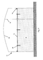
- Fig. 1 illustrates a large storage tank 10 having a cover 12 floating on liquid 14 contained in the tank.
- This floating cover 12 is made up of a number of prefabricated sandwich panels joined together.
- the cover 12 includes other components for operation of the storage tank.
- a ring flange with a cross-sectional shape of an inverted "L" is provided around the peripheral edge of the cover.
- a flexible metal seal 16 is mounted on this flange to co-operate with the internal wall of the tank to keep the content of the tank beneath the cover 12 and to prevent external contaminants from entering.
- a plurality of vents is equally spaced along the ring flange is to allow for expansion or contraction of vapour that may be present in the tank as its temperature varies during the day.
- Other types of vents may also be provided, for example a vacuum breaker vent to allow the liquid in the tanks to be emptied, when the cover is resting on the tank floor and is no longer floating. This is to prevent damage to the cover caused by negative pressure when the balance of the content is pumped out.
- Draining or sampling points are arranged in order to allow samples of the contents of a tank to be taken. Further, a gauge pole well is also provided for determining the quantity of the content in the tank.
- Fittings such as a wire rope 18 fixed between the roof and floor of the tank and passing through the cover prevent the cover 12 from rotating.
- Vertically extending legs 20 are spaced apart below the cover 12 at regular intervals. These legs are provided to support the cover 12 when the scaffolding has been removed after the cover is completed and before the tank 10 is filled with sufficient liquid for the cover 12 to float. The legs 20 also provide headroom below the cover 12 for maintenance purposes. A hatch-cover complete with seals over a man-hole is also provided for maintenance purposes.
- a roof 22 covers the whole tank 10.
- a prefabricated sandwich panel 30, used to make up the floating cover 12 is shown in cross-section in Fig. 2 . Because each panel is very much thinner than it is long or wide, the relative depth and width is distorted in Fig. 2 and other figures. Likewise, there is a distortion in the relative thicknesses of the different layers.
- Each panel 30 has a lower glass-fibre reinforced composite layered portion 32, an upper glass-fibre reinforced composite layered portion 34 and a honeycomb section (portion) 36, to provide buoyancy, sandwiched between the lower and upper layered portions 32,34.
- Each portion is preferably continuous, in that there are no holes or gaps all the way through them. The panels are joined together, with the lower layered portions 32, edge 38 to edge 38, to form the entire floating cover 12.
- Both the lower layered portion 32 and the upper layered portion 34 are themselves composite, laminar structures of several layers, each of which contains a liquid polymerise resin such as an epoxy resin, for instance epoxy vinyl ester resin, and glass fibres.
- a liquid polymerise resin such as an epoxy resin, for instance epoxy vinyl ester resin
- the glass fibres are orientated in different patterns or directions, at least relative to immediately adjacent layers to provide each panel with required strength and other desired mechanical properties.
- the lower and upper layered portions 32,34 are mirror images of each other, although extending different amounts in the plane of each panel 30.
- the lowermost (outer) layer 42 is a V-layer.
- a first mat or M-layer 44 Above the V-layer 42 is a first mat or M-layer 44.
- An R-layer 46 is disposed above the first M-layer 44.
- a second M-layer 48, of a similar composition to the first M-layer 44 is provided on top of R-layer 46. This is the topmost layer of the lower layered portion 32 and is adjacent the underside of the honeycomb section 36.
- the upper layered portion 34 is the inverse of the lower layered portion 32, with a V-layer 52 uppermost, above a first M-layer 54, above a R-layer 56 above a second M-layer 58, which is adjacent the topside of the honeycomb section 36.
- the V-layer 52, first M-layer 54, R-layer 56 and second M-layer 58 of the upper layered portion 34 have the same general composition as their corresponding layers in the lower layered portion 32.
- the V-layers (surface veil layers) 42, 52 have a surfacing veil glass fibre mat of C glass reinforcements and have carbon (and colour pigments if desired) and enhance the surface finish as well as providing weather protection and corrosion resistant properties. Typically they are about 90 - 95% by weight of resin and about 0.5 - 0.6 mm thick. Different V-layers within the same panel can be of differing construction.
- the M-layers (mat layers) 44, 48, 54, 58 have a chopped strand mat of glass fibres that are of certain lengths but are randomly orientated. Typically they are about 60 - 70% by weight of resin and about 1.1 - 1.2 mm thick.
- the M-layers absorb relatively more resin and give relatively higher resistance to corrosion to the composite layered portions 32, 34. Different M-layers within the same panel can be of differing construction.
- the R-layers (woven roving layers) 46, 56 have a woven roving mat of glass reinforcements that are woven in two perpendicular directions. Typically they are about 40 - 50% by weight of resin and about 1.1 - 1.2 mm thick. Due to the orientations of the reinforcement, the R-layers provide mechanical strength in two directions. The lower resin absorption of these layers increases the glass to resin ratio with consequent increased mechanical strength. Different R-layers within the same panel can be of differing construction.
- the honeycomb layer 36 is made of a polypropylene core, with two membranes on each side.
- An inner membrane permanently attaches to the core and acts as a seal to prevent resin penetration into the cells of the core.
- An outer membrane of a nonwoven thermoplastic mat is porous and allows the resin of the composite layered portions (when wet) to penetrate and bond to the membrane's surface. The resulting bond contributes to the overall structural integrity of each panel 30.
- This honeycomb layer 36 and its core may be substituted with other types of lightweight core materials as desired or appropriate.
- the panels 30 are prefabricated at a factory. Each panel is typically 2.2 m square, this size being selected on a weight of about 70-80 kg per panel and general cumbersomeness. Each panel is not too heavy or large for a group of four to manhandle. As most storage tanks are cylindrical, a cover for such a tank would also be circular. This means that not all panels will be square, but some will have a rounded edge according to the overall radius of the tank.
- the composite is made in a large continuous and uniform sheet which is cut into appropriately sized panels 30. Portions of each panel are then removed around its edges to give it a stepped form, as is shown in Fig. 2 .
- the upper layered portion 34 and honeycomb section 36 are removed from a strip around every edge, in this example the strip is 0.1m wide.
- the lower layered portion 32 extends 0.1m beyond the upper layered portion 34 and honeycomb section 36 in an exposed portion 50 in each direction in the plane of the panel 30.
- the top V-layer 52 is stripped back a bit further at its edges, leaving an exposed strip 40 of the top first M-layer 54. Again this strip is 0.1m wide in this example.
- the panels do not have to be formed in this way, the stepped form can be achieved in the original fabrication stage or in other ways.
- form work scaffolding is erected and a platform is provided so that the panels 30 making up the entire cover 12 can be laid out with contiguous contact between the edges of the lower layered portions 32.
- the upper, horizontal surfaces are roughened with sandpaper, emery cloth or similar abrasive (for example having a grade size of about 30), if this has not been already been done.
- the resulting dust is removed by vacuum cleaning, otherwise the residue may cause weak bonding and joint failure.
- FIG. 3 A joint between adjacent panels 30 is shown in Fig. 3 .
- An exploded view of this is shown in Fig. 4 .
- the resin used in the V-layer is then applied to the extended facing edges 38 of the lower layered portions 32.
- a reinforcing structure is mounted over the joints between adjacent panels 30.
- the gap is filled with what amounts to a narrower inverted panel with the top V-layer 52 completely removed. That is there is a reinforcing infill composite 60, having a first M-layer 62 in contact with the abutting second M-layers 48 of two abutting lower layer portions 32. Above this is a first R-layer 64, then a second M-layer 66. Atop this is a honeycomb structure 68, on top of which is a third M-layer 70, then a second R-layer 72, then a fourth M-layer 74 and finally a topmost V-layer 76.
- the infill composite 60 Whilst it is possible to prefabricate the infill composite 60 in panels, for improved strength it is preferred that they be made in situ.
- a catalysed resin is applied to the exposed and roughened surfaces 50 of the second M-layers 48 and the infill composite is applied one layer at a time, either with each layer prefabricated or more preferably each layer made in situ, with some of the resin seeping down between the abutting edges 50 of the panels to help join them together. After each layer is laid down, it is compacted and air bubbles that may be present are rolled out, for example using metal rollers.
- a catalysed resin is applied to the underside of the infill honeycomb structure 68 and this is applied to the top of the infill second M-layer 66. It is held down by weights until it has completely cured.
- An infill top structural infill portion 80, with the remaining layers, is then applied to the top of the infill honeycomb structure 68. Again this is done on a layer by layer basis, compressing the layers and rolling out the air bubbles each time. This completes the joint. Once all the cover joints have been completed, the top surface can be finished off with any required top coat.
- the creation of the infill composite 60 reflects the creation of the initial composite from which the panels are formed. Thus if there are additional or fewer processes in creating that, they could be reflected in the creation of the infill. This means that the infill has similar properties to the panels. Additionally it means that the heights of various layers of the infill correspond to heights of other layers in the panels. In particular, the top of the infill honeycomb structure 68 is level with the top of the exposed top first M-layer 54 and the infill third M-layer 70 is level with the top V-layer 52.
- top infill structural portion 80 that is the third M-layer 70, second R-layer 72, fourth M-layer 74 and topmost V-layer 76, extend further outwards relative to the rest of the infill structure 60. It is about 0.4m wide, whilst the infill honeycomb structure 68 and lower structural infill portion are about 0.2m, or a little less wide (to allow resin between the panels 30 and the infill composite 60. This means that the top infill structural portion 80 extends as far as the exposed top first M-layer 54, the infill third M-layer 70 bonding to the top exposed surface 40 of the top first M-layer 54.
- the top V-layer 76 may also be extended down the exposed sides of the top structural infill portion 80, to join up with the top V-layers 52 of the panels being joined, to complete the outer protective layer.
- the form work is removed from the underside and exposed edges on the underside are sealed and laminated with a further V-layer. This is to improve corrosion resistance, rather than being necessary for strength.
- the construction of the cover 12 from separate panels 30 by this method can be carried out from just one side, the top side, although the preferred finishing step after completion is carried out below. This is partly due to the fact that the panels are connected edge to edge, with vertical edges next to each other and without overlap. This means that people do not have to work in cramped and badly ventilated conditions underneath, thereby improving safety. Breathing equipment is therefore not necessary, or does not need to be used so much and there are improvements in work conditions and costs.
- the prefabricated panels are joined together to form an entire cover having similar structural layers.
- This method provides a cover that is mainly prefabricated at the factory and minimal work is carried out on site. As the working conditions and quality at the factory is easily controlled, this means that the structural integrity of the cover thus formed is relatively superior to that if .formed on site. With this method, the entire job for completing a cover is also shorter, which means cost savings.
- the lower and upper layered portions 32,34 are formed layer by layer in the factory to suit each application.
- the resins binding the fibres in each layer may also differ from the adjacent layers, and together with the glass-fibres, each layer provides the composite plate unique mechanical properties.
- the composition and number of layers of panels can vary from job to job, within the scope of the invention.
- each lower and upper layered portion 32,34 is 4 mm thick and the honeycomb layer is 60 mm thick.
- the core thickness, the spacing between the supporting legs, the self-weight of the cover, the strength of the resin and glass fibres, the rigidity of the cover, the composite plate thickness or the number of laminates may vary, all relative to each other.
- the honeycomb thickness or number of honeycomb layer may be increased for greater strength or rigidity. Yet it is also possible to maintain a common composite thickness and strength by providing more supporting legs at the lower side of the cover.
- the exposed portions in the described embodiment are 0.1m wide.
- the invention covers other possibilities as required. For example, they could range from 0.05 to 0.2m or to other widths.
- the extension of the lower layered portion 32 relative to the upper layered portion 34 and core 36, and the overlap of the top infill structural portion 80 need not be 0.1m but could be different from each other and can be varied as desired, for instance depending on the type of resin used and the shear forces induced at these joints, etc.
- the steps do not need to have vertical faces, but can be sloped.
- the materials chosen for the cover need to be compatible with the liquid in the tank.
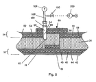
- testing ports 90 may be provided at the infill composite section 60 near the cut edges of the honeycomb 36, 68 as shown in Fig. 5 .
- the infill honeycomb sections 68 are generally slightly smaller than the space between two adjacent honeycomb sections 36. This is to allow for dimensional tolerances in the fabrication of the panels 30 and honeycomb sections 68. As a result there is a gap 92 in between the cut edges of the honeycomb sections 36, 68, and this gap 92 runs along the fabricated joints between the panels 30. In an integrally constructed floating cover 12, the gap 92 is sealed by the lower composite layers 32, 78, upper composite layers 34, 80 and honeycomb sections 36, 68.
- a hole 94 is drilled through the upper composite layer 80 to the cut edge of the honeycomb 68.
- Epoxy resin such as that mixed with the catalyst used in fabricating the panels 30 is applied onto the walls of the hole 94.
- a sleeve 96 preselected to suit the hole 94, is inserted into the hole 94, and the gap, if any, between the hole 94 and the sleeve 96 is further filled with epoxy and catalyst so that there is no void between the hole 94 and the sleeve 96.
- the bonding between the composite layer 80 and the sleeve 96 can thereby be as strong as the composite layer 80 itself.
- the sleeve 96 has a through hole with an internal thread. In the process of inserting the sleeve 96 in the hole 94, precautions are taken not to allow the epoxy to block the internal hole of the sleeve 96.
- the upper end of the sleeve 96 may be temporary closed with a plug 98 (which may extend all the way to the bottom of the sleeve 96).
- a number of test ports 90 are provided at spaced apart positions.
- One such port 90 should normally be sufficient, as the gaps 92 are all joined together. However, more than one is provided to give the tester a choice of testing positions or in case some groups of the gaps are isolated.
- a nipple 100 is attached to the test port 90 which is not plugged. The nipple 100 is screwed into the internal thread of the sleeve 96 so as to form an airtight joint.
- a first end of a T-joint 102 is connected to the other end of the nipple 100. The other two distal ends of the T-joint 102 are connected to a pressure gauge 104 and a shutoff valve 106.
- the shutoff valve 106 has a thread that is suitable for connection to a line from a pump 200.
- the pump 200 is operated to deliver a gas, for example air or nitrogen, to the enclosed space created by the gap 92 between the panels 30 in the floating cover 12.
- the gas is delivered with a positive pressure, for example 0.005 bar gauge (or 50 mm water head), and the shutoff valve 106 is closed once a predetermined pressure is attained.
- the pressure in the enclosed space in the floating cover 12 is monitored over a period of time, for example 24 hours. If this pressure is maintained over this time period, the joints formed in the panel are airtight. If the pressure is not maintained, one or more joints is not airtight.
- the actual leaking joints may be detected by applying a liquid such as a soap solution to a portion of the floating cover and observing air bubbles from a defective portion of the cover 12. The defective portion of the cover can then be identified, repaired and tested again to ensure that the joints formed in the floating cover 12 are not defective.
- a liquid such as a soap solution
- a vacuum pressure may be used instead of a positive pressure. Accordingly, the pressure gauge must be suitable for vacuum sensing. However, to identify the defective portion of the cover with ease, a positive pressure and a liquid such as a soap solution are used.
- these testing ports 90 are plugged up to prevent entry of vapour or liquid into the cover.
- the hole 94 is smooth in the above embodiment, alternatively, the hole 94 may be threaded to fit an externally threaded sleeve.
- Another alternative is to locate the sleeve 96 in the infill composite section 60 as the infill composite section 60 is made.
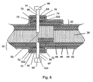
- test ports are provided with the sleeve 96 with a flange 300 having an internal hole through which the sleeve 96 is positioned and to which the sleeve 96 is welded, to form a test port 91 as shown in Fig. 6 .
- the flange 300 and sleeve 96 may both be made of metal, for example, steel or aluminium.
- the flange 300 is toroidal, for example with an outside diameter of about 70 mm and a thickness from about 3 mm to about 5 mm.
- Other shapes of the flange 300 are also suitable, although preferably they can fit an inscribed circle within them, for example of at least 70 mm diameter.
- the sleeve 96 has an internal thread and an internal bore of 12-mm, for example, nominal diameter. In the preferred embodiment, the internal pressure is to be 0.005 bar gauge.
- the external diameter of the sleeve may, for instance, be 25 mm.
- the diameter of the flange through hole matches the external diameter of the sleeve 96.
- the external diameter of the sleeve 96 might change, and so would the size of the flange through hole.
- the sizes of the sleeve 96 and flange 300 are not limited by these examples, and the sizes of the sleeve 96 and flange 300 are merely design choices.
- the sleeve 96 and flange 300 which are prejoined together, are inserted during the formation of the infill composite portion 60.
- the hole 94 is drilled.
- Catalysed epoxy is applied to the walls of the hole 94 and the sleeve 96 is inserted such that there is no void between the hole 94 and sleeve 96, as done in the previous embodiment.
- Catalysed epoxy is also applied to the upper, lower and edge surfaces of the flange 300.
- a plurality of drain ports 191 are provided on the lower side of the floating cover 12. These drain ports 191 are provided so that any liquid that has entered the cover 12, such as the liquid from the storage tank 10 (which entered during maintenance or repair of the floating cover 12 or otherwise) or rain water collected on the uncompleted floating cover 12 during its fabrication, can be drained out.
- Each drain port 191 is fabricated in the same manner as a test port 91, i.e. having a flange 302 welded to a sleeve 97.
- a plurality of positions directly below the gap 92 are marked on the lower surface of the cover 12. These positions are spaced apart as desired. At each position, a hole 95 is drilled through the structural layers 42,44,46,48 of the cover 12. The V-layer 42 in the area around each hole 95 is removed, if not previously done, over an area extending beyond the size and shape of the flange 302.
- the flange 302 is positioned on the sleeve 97 and they are prejoined together, such that when of the sleeve 99 is inserted into the hole 95 until the flange 302 is in contact with the exposed area of the outer M-layer 44 and the upper end of the sleeve 97 is about flush with the inner M-layer 48.
- Catalysed epoxy is applied onto the exposed area of the outer M-layer 44, onto the surfaces of the hole 95 and also on the upper, lower and edge surfaces of the flange 302.
- the sleeve 97 is then inserted into the hole 95 until the flange 302 is in contact with the exposed layer 44.
- Each drain port is mounted and secured onto the cover 12 by forming a set of structural layers of fibreglass 70,72,74 over and around the flange 300 of the drain port 191 similar to layers 70,72,74 over and around the test port 91.
- a V-layer similar to layer 42 is formed over the exposed surfaces of the newly laid structural layers 70,72,74 and the exposed area of layer 44 to complete the finishing and protective coat on the lower surface of the floating cover.
- test ports 91 and drain ports 191 may have one or more test ports 91 without any drain ports 191 and yet further embodiments may have one or more drain ports 191 without any test ports 91.
- cover having a slight camber and/or rainwater drainage which is particularly suitable for a tank without a roof.
- the cover need not be round and it may be square, rectangular, or of any shape for fitting into any storage tank or reservoir to function as a cover. Instead of forming the in-fill sandwich sections on site, these could be prefabricated at the factory.
Landscapes
- Engineering & Computer Science (AREA)
- Mechanical Engineering (AREA)
- Filling Or Discharging Of Gas Storage Vessels (AREA)
Claims (48)
- Eine im Wesentlichen ebene schwimmfähige Platte (30) für eine schwimmende Abdeckung (12) für einen Flüssigkeitsspeichertank (10), bei welcher die Platte erste (32) und zweite (36) Abschnitte in Kontakt miteinander umfasst, dadurch gekennzeichnet, dass:der erste Abschnitt (32) eine Ausdehnung in der Ebene der Platte und eine erste, dem zweiten Abschnitt zugewandte Seite aufweist;der zweite Abschnitt (36) eine Ausdehnung in der Ebene der Platte aufweist, wobei diese Ausdehnung kleiner ist als die Ausdehnung des ersten Abschnitts; undder erste Abschnitt (32) auf der ersten Seite einen freiliegenden Abschnitt (50) in jeder Richtung in der Ebene der Platte (30) aufweist.
- Platte nach Anspruch 1, bei welcher der zweite Abschnitt (36) eine Kante aufweist und sich der freiliegende Abschnitt (50) über den gesamten Weg um die Kante des zweiten Abschnittes (36) erstreckt.
- Platte nach Anspruch 1 oder 2, bei welcher der erste Abschnitt (32) eine Laminatstruktur ist.
- Platte nach irgendeinem der vorhergehenden Ansprüche, bei welcher der erste Abschnitt (32) eine glasverstärkte Struktur ist.
- Platte nach irgendeinem der vorhergehenden Ansprüche, bei welcher der zweite Abschnitt (36) schwimmfähig ist.
- Platte nach irgendeinem der vorhergehenden Ansprüche zur Verwendung mit dem zweiten Abschnitt (36), der sich über dem ersten Abschnitt (32) befindet.
- Platte nach irgendeinem der vorhergehenden Ansprüche, bei welcher die ersten und zweiten Abschnitte (32), (36) kontinuierlich sind.
- Platte nach irgendeinem der vorhergehenden Ansprüche, weiterhin einen dritten Abschnitt (34) in Kontakt mit dem zweiten Abschnitt (36) auf der anderen Seite des zweiten Abschnitts (36) von dem ersten Abschnitt (32) umfassend.
- Platte nach Anspruch 8, bei welcher der dritte Abschnitt (34) eine erste Seite aufweist, die dem zweiten Abschnitt (36) zugewandt ist, und eine Ausdehnung in der Ebene der Platte aufweist, wobei die Ausdehnung gleich oder kleiner als die Ausdehnung des zweiten Abschnitts (36) ist.
- Platte nach Anspruch 8 oder 9, bei welcher der dritte Abschnitt (34) eine Laminatstruktur aufweist.
- Platte nach Anspruch 10, bei welcher die Schichten (52, 54, 56, 58) des dritten Abschnitts (34) jeweils eine Ausdehnung in der Ebene der Platte aufweist, und die Ausdehnung der Schicht (52) des dritten Abschnitts (34) am weitesten entfernt von dem zweiten Abschnitt (36) kleiner als die Ausdehnung der Schicht (58) des dritten Abschnitts (34) am nächsten zum zweiten Abschnitt (36) ist.
- Platte nach irgendeinem der Ansprüche 8 bis 11, bei welcher der dritte Abschnitt (34) eine glasverstärkte Struktur ist.
- Platte nach irgendeinem der Ansprüche 8 bis 12, bei welcher der dritte Abschnitt (34) dieselbe Konstruktion wie der erste Abschnitt aufweist.
- Platte nach irgendeinem der vorhergehenden Ansprüche, bei welcher die Platte im Wesentlichen ein Parallelepiped in der Ebene der Platte ist.
- Eine Vielzahl von Platten, wobei jede nach irgendeinem der vorhergehenden Ansprüche definiert ist, bei welcher der erste Abschnitt (32) jeder Platte eine Kante (38) aufweist, die im Allgemeinen senkrecht zu der Ebene der Platte ist, und die Kanten (38) der ersten Abschnitte (32) benachbarter Platten aneinander anstoßen.
- Vielzahl von Platten nach Anspruch 15, weiterhin eine Vielzahl von Füllabschnitten (60) umfassend, wobei jeder Füllabschnitt (60) sich in Kontakt mit den freiliegenden Abschnitten (50) zweier benachbarter und aneinanderstoßender Platten erstreckt.
- Vielzahl von Platten nach Anspruch 16, bei welcher jeder Füllabschnitt (60) einen ersten Füllabschnitt (78), einen zweiten Füllabschnitt (68) und einen dritten Füllabschnitt (80) umfasst, wobei sich der zweite Abschnitt (68) zwischen dem ersten Füllabschnitt (78) und dem dritten Füllabschnitt (80) befindet, und der zweite Füllabschnitt (68) die gleiche Konstruktion wie ein zweiter Plattenabschnitt (36) aufweist.
- Vielzahl von Platten nach Anspruch 17, bei welcher jeder dritte Füllabschnitt (80) dieselbe Konstruktion wie ein invertierter erster Plattenabschnitt (32) aufweist.
- Vielzahl von Platten nach Anspruch 17 oder 18, bei welcher in jedem Füllabschnitt (60):der dritte Füllabschnitt (80) eine Ausdehnung in der Ebene der Platten aufweist, zwischen welchen sich der Füllabschnitt (60) erstreckt und eine erste Seite dem zweiten Füllabschnitt (68) zugewandt ist;der zweite Füllabschnitt (68) eine Ausdehnung in der Ebene der Platten aufweist, zwischen welchen sich der Füllabschnitt (60) erstreckt, dessen Ausdehnung kleiner als die Ausdehnung des dritten Füllabschnitts (80) ist; unddie Ausdehnung des dritten Füllabschnitts (80) nicht durch den zweiten Füllabschnitt (68) abgedeckt ist, der sich mit äußeren Oberflächen (40) der Platten erstreckt und in Kontakt steht, zwischen welchen sich der Füllabschnitt (60) erstreckt.
- Vielzahl von Platten nach Anspruch 19, soweit er zumindest von Anspruch 8 abhängig ist, bei welcher die Ausdehnung des dritten Füllabschnitts (80), die nicht durch den zweiten Füllabschnitt (68) abgedeckt ist, sich auf und in Kontakt mit äußeren Oberflächen (40) der dritten Plattenabschnitte (34) der Platten erstreckt, zwischen welchen sich der Füllabschnitt (60) erstreckt.
- Vielzahl von Platten nach Anspruch 20, soweit er zumindest von Anspruch 11 abhängig ist, bei welcher die Ausdehnung des dritten Füllabschnitts (80), die nicht durch den zweiten Füllabschnitt (68) abgedeckt ist, in Kontakt mit den Schichten (54, 56, 58) der dritten Plattenabschnitte (34) steht, zwischen welchen sich der Füllabschnitt (60) erstreckt, anders als die Schicht (52) jeder der Platten, die am weitesten von dem zweiten Plattenabschnitt (36) entfernt sind.
- Vielzahl von Platten nach irgendeinem der Ansprüche 17 bis 21, soweit sie von zumindest Anspruch 10 abhängig sind, bei welcher jeder erster Füllabschnitt (78) dieselbe Konstruktion wie ein dritter Plattenabschnitt (80) aufweist ohne die Schicht (76), die am weitesten von dem zweiten Plattenabschnitt (68) entfernt ist und umgekehrt.
- Vielzahl von Platten nach irgendeinem der Ansprüche 16 bis 22, weiterhin umfassend:einen oder mehrere Abflussanschlüsse (91, 97), die sich von einer Grenze zwischen den Füllabschnitten (60) und einem der zweiten Plattenabschnitte (36) erstrecken.
- Vielzahl von Platten nach Anspruch 23, soweit er zumindest von Anspruch 3 abhängig ist, bei welcher sich einer oder mehrere der Abflussanschlüsse (97) von einem ersten Ende davon bündig mit einer innersten Laminatschicht (48) der Laminatstruktur erstrecken.
- Vielzahl von Platten nach irgendeinem der Ansprüche 15 bis 24, bei welcher die Platten vorproduziert werden, bevor sie ausgelegt und miteinander verbunden werden, an dem Ort, wo sie zu verwenden sind.
- Vielzahl von Platten nach irgendeinem der Ansprüche 16 bis 24 oder nach Anspruch 25, soweit er von zumindest Anspruch 16 abhängt, weiterhin umfassend:zumindest einen Testanschluss (90), der sich von einer Grenze zwischen dem Füllabschnitt (60) und einem der zweiten Plattenabschnitte (36) zu einer äußeren Oberfläche von einem der dritten Plattenabschnitte (34) erstreckt.
- Schwimmfähige Abdeckung für einen Flüssigkeitsspeichertank mit einer Vielzahl von Platten nach irgendeinem der Ansprüche 15 bis 25.
- Verfahren zum miteinander Verbinden einer Vielzahl, im Allgemeinen planarer, schwimmfähiger Platten zur Verwendung zum Bilden einer schwimmenden Abdeckung, wobei jede Platte (30) erste und zweite Abschnitte (32, 36) umfasst, die miteinander in Kontakt stehen, wobei der erste Abschnitt (32) jeder Platte eine Ausdehnung in der Ebene der Platte und eine erste Seite aufweist, die dem zweiten Abschnitt (36) zugewandt ist, und wobei der zweite Abschnitt (36) jeder Platte eine Ausdehnung in der Ebene der Platte aufweist, wobei die Ausdehnung geringer ist als die Ausdehnung des ersten Abschnitts (32); und der erste Abschnitt (32) auf der ersten Seite einen freiliegenden Abschnitt (50) in jeder Richtung der Ebene der Platte (30) aufweist, und wobei die Vielzahl von Platten miteinander angeordnet sind, wobei benachbarte Platten aneinander anstoßen, und wobei die Kanten (38) der ersten Abschnitte (32) benachbarter Platten, welche senkrecht zu den Ebenen der Platten sind, die in Kontakt stehen, dadurch gekennzeichnet, dass das Verfahren den folgenden Schritt umfasst:Einfügen von Füllabschnitten (60) zwischen benachbarte Platten, wobei sich die Füllabschnitte (60) in Kontakt mit den freiliegenden Abschnitten (50) benachbarter und aneinander anstoßender Platten erstrecken.
- Verfahren zum miteinander Verbinden einer Vielzahl von im Allgemeinen ebenen, schwimmfähigen Platten zur Verwendung zur Bildung einer schwimmenden Abdeckung, bei welchem jede Platte (30) nach irgendeinem der Ansprüche 1 bis 14 definiert ist, und bei welchem die Vielzahl von Platten miteinander angeordnet werden, so dass benachbarte Platten aneinander anstoßen, und die Kanten (38) der ersten Abschnitte (32) benachbarter Platten, die senkrecht zu den Ebenen der Platten sind, die in Kontakt stehen, wobei das Verfahren den folgenden Schritt umfasst:Einfügen von Füllabschnitten (60) zwischen benachbarte Platten, wobei sich die Füllabschnitte (60) in Kontakt mit den freiliegenden Abschnitten (50) benachbarter und anstoßender Platten befinden.
- Verfahren nach Anspruch 28 oder 29, bei welchem die Vielzahl von Platten nicht vor Ort vorproduziert werden, bevor sie zum miteinander Verbinden positioniert werden.
- Verfahren nach Anspruch 30, weiterhin den folgenden Schritt umfassend, vor dem Einfügeschritt, die freiliegenden Oberflächen (50) der Platten aufzurauen und den dabei erzeugten Staub wegzuputzen.
- Verfahren nach irgendeinem der Ansprüche 28 bis 31, bei welchem der Einfügeschritt umfasst:Anordnen einer ersten Füllschicht (62) über den freiliegenden Abschnitten (50) benachbarter und aneinander angrenzender Platten; undjeweiliges (einzelnes?) Anordnen von einer oder mehreren weiteren Füllschichten (64, 66) über der ersten Füllschicht (62).
- Verfahren nach Anspruch 32, weiterhin den Schritt des Rollens jeder Füllschicht (62, 64, 66) umfassend, nachdem sie um Luft zu entfernen angeordnet ist.
- Verfahren nach Anspruch 32 oder 33, bei welchem zumindest die erste Füllschicht (62) eine nichtlaminierte Schicht ist.
- Verfahren nach irgendeinem der Ansprüche 28 bis 34, bei welchem die Platten sicher miteinander verbunden werden durch Menschen, die nur auf einer Seite der Abdeckung arbeiten.
- Verfahren nach irgendeinem der Ansprüche 28 bis 34, das zum Erzeugen einer schwimmfähigen Abdeckung nach Anspruch 27 verwendet wird.
- Verfahren nach irgendeinem der Ansprüche 28 bis 34 als ein Verfahren zum Bilden einer schwimmenden Abdeckung.
- Verfahren nach irgendeinem der Ansprüche 28 bis 37, bei welchem die Platten sicher miteinander verbunden werden durch Menschen, die nur auf einer Seite der Abdeckung arbeiten.
- Verfahren nach irgendeinem der Ansprüche 28 bis 37, umfassend die folgenden Schritte:Anordnen einer Vielzahl von Platten auf einem Arbeitsstück;miteinander Verbinden der Platten; undEntfernen des Arbeitsstücks;wobei der Verbindungsschritt vor dem Entfernungsschritt ausschließlich von einer Seite der Abdeckung durchgeführt wird.
- Verfahren zum Testen der Integrität der Verbindungen in einer schwimmenden Abdeckung, die durch eine Vielzahl von Platten nach irgendeinem der Ansprüche 16 bis 24 gebildet ist, soweit sie von zumindest Anspruch 8 abhängig sind, oder nach Ansprüchen 25 oder 27, soweit sie zumindest von den Ansprüchen 8 und 16 abhängig sind, dadurch gekennzeichnet, dass das Verfahren umfasst:Bereitstellen von zumindest einem ersten Testanschluss (90), der sich von einer Grenze zwischen dem Füllabschnitt (60) und einem der zweiten Plattenabschnitte (68) zu der äußeren Oberfläche von einem der dritten Plattenabschnitte (34) erstreckt;Aufbringen einer Druckdifferenz zwischen dem Testanschluss (90) oder einem der Testanschlüsse (90) und der Außenseite der Abdeckung;Bestimmen, ob ein Leck zwischen dem Testanschluss (90) oder einem der Testanschlüsse (90) und der Außenseite der Abdeckung besteht; und wenn es ein Leck gibt, Identifizieren des Lecks.
- Verfahren zum Testen nach Anspruch 36, bei welchem das Aufbringen einer Druckdifferenz das Pumpen eines Gases in einen Testanschluss (90) oder einen der Testanschlüsse (90) mit einem vordefinierten Druck umfasst.
- Verfahren zum Testen nach Anspruch 41, bei welchem das Gas Luft oder Stickstoff ist.
- Verfahren nach irgendeinem der Ansprüche 36 bis 42, bei welchem das Aufbringen einer Druckdifferenz weiterhin das Abdichten des Testanschlusses (90) oder eines der Testanschlüsse (90) mit einem vordefinierten Druck umfasst.
- Verfahren zum Testen nach Anspruch 43, bei welchem das Bestimmen, ob ein Leck existiert, das Bestimmen umfasst, ob es eine Änderung des Drucks über die Zeit in dem einen Testanschluss (90) oder in einem der Testanschlüsse (90) gibt.
- Verfahren zum Testen nach irgendeinem der Ansprüche 36 bis 44, bei welchem das Identifizieren des Lecks ein Aufbringen einer Flüssigkeit auf Abschnitte der schwimmenden Abdeckung umfasst, und das Beobachten von Blasen, die sich in der Flüssigkeit aufgrund eines Lecks bilden.
- Verfahren zum Testen nach Anspruch 45, bei welchem die Flüssigkeit eine Seifenlösung ist.
- Verfahren zum Testen nach irgendeinem der Ansprüche 36 bis 46, weiterhin das Bereitstellen einer Hülse (96) in dem zumindest einen Testanschluss (90) umfassend, um die Druckdifferenz auf den zumindest einen Testanschluss (90) aufzubringen.
- Verfahren zum Testen nach irgendeinem der Ansprüche 36 bis 47, bei welchem eine Vielzahl von Testanschlüssen (90) bestehen und alle bis auf einen abgedichtet sind, wenn die Druckdifferenz auf diesen einen aufgebracht wird.
Applications Claiming Priority (3)
| Application Number | Priority Date | Filing Date | Title |
|---|---|---|---|
| SG200300247 | 2003-01-31 | ||
| SG200300247 | 2003-01-31 | ||
| PCT/SG2004/000029 WO2004067408A1 (en) | 2003-01-31 | 2004-01-30 | Panels for floating covers, floating covers and methods for making them |
Publications (3)
| Publication Number | Publication Date |
|---|---|
| EP1597174A1 EP1597174A1 (de) | 2005-11-23 |
| EP1597174A4 EP1597174A4 (de) | 2006-12-27 |
| EP1597174B1 true EP1597174B1 (de) | 2010-10-06 |
Family
ID=32823048
Family Applications (1)
| Application Number | Title | Priority Date | Filing Date |
|---|---|---|---|
| EP04706916A Expired - Lifetime EP1597174B1 (de) | 2003-01-31 | 2004-01-30 | Platte für schwimmende abdeckungen, schwimmende abdeckungen und herstellungsverfahren dafür |
Country Status (4)
| Country | Link |
|---|---|
| US (1) | US20070023432A1 (de) |
| EP (1) | EP1597174B1 (de) |
| DE (1) | DE602004029446D1 (de) |
| WO (1) | WO2004067408A1 (de) |
Families Citing this family (12)
| Publication number | Priority date | Publication date | Assignee | Title |
|---|---|---|---|---|
| AU2002300784B2 (en) * | 2001-08-29 | 2006-10-19 | Warwick Hill | Membrane jointing system |
| SG173665A1 (en) * | 2009-02-13 | 2011-09-29 | Dynaglass Reinforced Plastic Pte Ltd | Panel for floating covers |
| US8221030B1 (en) | 2009-07-02 | 2012-07-17 | Versaflex, Inc. | Cover for a liquid reservoir |
| US10138052B2 (en) | 2013-07-01 | 2018-11-27 | Vertical Tank, Inc. | Floating roof tank having support structures for protecting the peripheral seal |
| US9359131B2 (en) | 2013-07-01 | 2016-06-07 | Vertical Tank, Inc. | Floating roof tank having support structures for protecting the peripheral seal |
| US9334106B2 (en) | 2013-08-01 | 2016-05-10 | Travis Jordan | Insulating tank cover |
| CN109132246B (zh) * | 2018-08-30 | 2023-07-04 | 浙江科赛新材料科技有限公司 | 油罐接头 |
| EP3702398A1 (de) * | 2019-02-26 | 2020-09-02 | World Link Industry Engineering GmbH | Schwimmdach für tanks, feuerfeste beschichtung dafür und verfahren zur herstellung davon |
| CN109928091B (zh) * | 2019-04-28 | 2020-01-17 | 沃德林科环保设备(北京)有限公司 | 一种玻璃钢浮盘施工方法 |
| CN110015516A (zh) * | 2019-04-28 | 2019-07-16 | 沃德林科环保设备(北京)有限公司 | 一种新型玻璃钢浮盘施工方法 |
| CN113944300B (zh) * | 2021-09-14 | 2023-03-17 | 广州地铁设计研究院股份有限公司 | 一种水动力防倒灌风井 |
| WO2025119474A1 (de) * | 2023-12-04 | 2025-06-12 | Ept - Environmental Protection Technology For Storage Tanks Gmbh | Feuerfestes schwimmdach für einen tank und verfahren zu dessen herstellung |
Family Cites Families (12)
| Publication number | Priority date | Publication date | Assignee | Title |
|---|---|---|---|---|
| US3249659A (en) * | 1961-07-19 | 1966-05-03 | Allied Chem | Method of making laminated panel structures |
| CA966430A (en) * | 1972-04-11 | 1975-04-22 | John Der Versteeg | Floating roof cover for storage tanks and method of making same |
| US3910452A (en) * | 1972-12-01 | 1975-10-07 | Sandborn Edmund | Floating cover for a storage tank |
| JPS532485B2 (de) * | 1973-11-15 | 1978-01-28 | ||
| US3895152A (en) * | 1973-12-26 | 1975-07-15 | Continental Oil Co | A composite cellular construction |
| US4189058A (en) * | 1978-03-13 | 1980-02-19 | The Dow Chemical Company | Floating thermally insulating tank covers |
| US4202460A (en) * | 1978-04-13 | 1980-05-13 | Imbeault Fernand A | Sectional floating cover |
| US4213280A (en) * | 1978-09-06 | 1980-07-22 | Novaro Investments Limited | Modular unit for the construction of floating decks of liquid storage tanks |
| GB2042615B (en) * | 1979-01-08 | 1982-12-15 | Sandborn E | Floating roof for storage tanks |
| US4461395A (en) * | 1981-07-20 | 1984-07-24 | Burnett Robert A | Reusable, modular, knockdown container |
| CA2021130A1 (en) * | 1990-07-13 | 1992-01-14 | Steven J. Coates | Full surface contact internal floating roof |
| BR9704844A (pt) * | 1997-02-03 | 1999-09-14 | Petroleo Brasileiro Sa | Teto flutuante não estrutural de alta elasticidade para tanques de armazenamento de líquidos. |
-
2004
- 2004-01-30 DE DE602004029446T patent/DE602004029446D1/de not_active Expired - Lifetime
- 2004-01-30 US US10/543,972 patent/US20070023432A1/en not_active Abandoned
- 2004-01-30 EP EP04706916A patent/EP1597174B1/de not_active Expired - Lifetime
- 2004-01-30 WO PCT/SG2004/000029 patent/WO2004067408A1/en not_active Ceased
Also Published As
| Publication number | Publication date |
|---|---|
| WO2004067408A9 (en) | 2006-12-28 |
| DE602004029446D1 (de) | 2010-11-18 |
| HK1084650A1 (en) | 2006-08-04 |
| WO2004067408A1 (en) | 2004-08-12 |
| EP1597174A4 (de) | 2006-12-27 |
| US20070023432A1 (en) | 2007-02-01 |
| EP1597174A1 (de) | 2005-11-23 |
Similar Documents
| Publication | Publication Date | Title |
|---|---|---|
| WO2010093328A1 (en) | Panel for floating covers | |
| EP1597174B1 (de) | Platte für schwimmende abdeckungen, schwimmende abdeckungen und herstellungsverfahren dafür | |
| CN109614719B (zh) | 一种基于bim技术的制冷机房装配式施工方法 | |
| US5037239A (en) | Underground concrete vault structure for hazardous liquid storage tanks | |
| US10968631B2 (en) | Structure reinforcement partial shell | |
| KR101412680B1 (ko) | Lng 탱크의 보조 멤브레인용 말단부 | |
| CN106284787B (zh) | 装配式叠合板安装及定位方法 | |
| AU2021106549A4 (en) | A construction method for an unbonded prestressed large-diameter reinforced-concrete thin-walled circular tank | |
| KR20100062393A (ko) | 지붕층 구조시스템 | |
| US8091728B2 (en) | Wet well apparatus with base form and installation method regarding same | |
| HK1084650B (en) | Panels for floating covers, floating covers and methods for making them | |
| JP3975240B2 (ja) | 高構造物の改修方法 | |
| CN112727217B (zh) | 一种在掩体内安装钢膜结构油罐的方法 | |
| WO2006085592A1 (ja) | 浸水浮上建築物およびその施工方法 | |
| CN207455614U (zh) | 一种烟囱防护内衬 | |
| EP3857004B1 (de) | Verfahren zur reparatur eines in wasser vorhandenen holzpfahls | |
| CN117386991A (zh) | 一种双层低温储罐组装施工方法 | |
| KR101056548B1 (ko) | 통기완충형 복합시트부를 포함하는 건물바닥의 방수구조 및 이의 방수시공방법 | |
| KR101557941B1 (ko) | 건축물의 옥상 방수 시공방법 | |
| Giancaspro et al. | Aerospace technology for strengthening of bridges | |
| RU2828905C1 (ru) | Способ сборки резервуара для хранения жидкостей | |
| US20240295126A1 (en) | Under ballasted roof substrate assembly | |
| CN117260041A (zh) | 一种结构稳固的非标多仓储罐安装工艺 | |
| KR20120103841A (ko) | 건물 바닥에 구비되는 비노출 타입의 다층형 복합방수구조 및 이의 방수시공방법 | |
| CN120506104A (zh) | 一种防腐层与预制构件集成的装配式水池的施工方法 |
Legal Events
| Date | Code | Title | Description |
|---|---|---|---|
| PUAI | Public reference made under article 153(3) epc to a published international application that has entered the european phase |
Free format text: ORIGINAL CODE: 0009012 |
|
| 17P | Request for examination filed |
Effective date: 20050801 |
|
| AK | Designated contracting states |
Kind code of ref document: A1 Designated state(s): AT BE BG CH CY CZ DE DK EE ES FI FR GB GR HU IE IT LI LU MC NL PT RO SE SI SK TR |
|
| AX | Request for extension of the european patent |
Extension state: AL LT LV MK |
|
| DAX | Request for extension of the european patent (deleted) | ||
| RBV | Designated contracting states (corrected) |
Designated state(s): DE FR GB NL TR |
|
| REG | Reference to a national code |
Ref country code: HK Ref legal event code: DE Ref document number: 1084650 Country of ref document: HK |
|
| A4 | Supplementary search report drawn up and despatched |
Effective date: 20061124 |
|
| RIC1 | Information provided on ipc code assigned before grant |
Ipc: B65D 90/02 20060101AFI20061120BHEP |
|
| 17Q | First examination report despatched |
Effective date: 20080918 |
|
| GRAP | Despatch of communication of intention to grant a patent |
Free format text: ORIGINAL CODE: EPIDOSNIGR1 |
|
| GRAS | Grant fee paid |
Free format text: ORIGINAL CODE: EPIDOSNIGR3 |
|
| GRAA | (expected) grant |
Free format text: ORIGINAL CODE: 0009210 |
|
| AK | Designated contracting states |
Kind code of ref document: B1 Designated state(s): DE FR GB NL TR |
|
| REG | Reference to a national code |
Ref country code: GB Ref legal event code: FG4D |
|
| REF | Corresponds to: |
Ref document number: 602004029446 Country of ref document: DE Date of ref document: 20101118 Kind code of ref document: P |
|
| REG | Reference to a national code |
Ref country code: NL Ref legal event code: T3 |
|
| REG | Reference to a national code |
Ref country code: HK Ref legal event code: GR Ref document number: 1084650 Country of ref document: HK |
|
| PLBE | No opposition filed within time limit |
Free format text: ORIGINAL CODE: 0009261 |
|
| STAA | Information on the status of an ep patent application or granted ep patent |
Free format text: STATUS: NO OPPOSITION FILED WITHIN TIME LIMIT |
|
| 26N | No opposition filed |
Effective date: 20110707 |
|
| REG | Reference to a national code |
Ref country code: DE Ref legal event code: R097 Ref document number: 602004029446 Country of ref document: DE Effective date: 20110707 |
|
| PGFP | Annual fee paid to national office [announced via postgrant information from national office to epo] |
Ref country code: FR Payment date: 20140108 Year of fee payment: 11 |
|
| PGFP | Annual fee paid to national office [announced via postgrant information from national office to epo] |
Ref country code: GB Payment date: 20140129 Year of fee payment: 11 |
|
| PGFP | Annual fee paid to national office [announced via postgrant information from national office to epo] |
Ref country code: DE Payment date: 20150127 Year of fee payment: 12 |
|
| PGFP | Annual fee paid to national office [announced via postgrant information from national office to epo] |
Ref country code: TR Payment date: 20150129 Year of fee payment: 12 |
|
| GBPC | Gb: european patent ceased through non-payment of renewal fee |
Effective date: 20150130 |
|
| PG25 | Lapsed in a contracting state [announced via postgrant information from national office to epo] |
Ref country code: GB Free format text: LAPSE BECAUSE OF NON-PAYMENT OF DUE FEES Effective date: 20150130 |
|
| REG | Reference to a national code |
Ref country code: FR Ref legal event code: ST Effective date: 20150930 |
|
| PG25 | Lapsed in a contracting state [announced via postgrant information from national office to epo] |
Ref country code: FR Free format text: LAPSE BECAUSE OF NON-PAYMENT OF DUE FEES Effective date: 20150202 |
|
| REG | Reference to a national code |
Ref country code: DE Ref legal event code: R119 Ref document number: 602004029446 Country of ref document: DE |
|
| PG25 | Lapsed in a contracting state [announced via postgrant information from national office to epo] |
Ref country code: DE Free format text: LAPSE BECAUSE OF NON-PAYMENT OF DUE FEES Effective date: 20160802 |
|
| PGFP | Annual fee paid to national office [announced via postgrant information from national office to epo] |
Ref country code: NL Payment date: 20200130 Year of fee payment: 17 |
|
| REG | Reference to a national code |
Ref country code: NL Ref legal event code: MM Effective date: 20210201 |
|
| PG25 | Lapsed in a contracting state [announced via postgrant information from national office to epo] |
Ref country code: NL Free format text: LAPSE BECAUSE OF NON-PAYMENT OF DUE FEES Effective date: 20210201 |
|
| PG25 | Lapsed in a contracting state [announced via postgrant information from national office to epo] |
Ref country code: TR Free format text: LAPSE BECAUSE OF NON-PAYMENT OF DUE FEES Effective date: 20160130 |