EP1597094B1 - Armature de sommet pour pneumatique radial - Google Patents
Armature de sommet pour pneumatique radial Download PDFInfo
- Publication number
- EP1597094B1 EP1597094B1 EP04710851A EP04710851A EP1597094B1 EP 1597094 B1 EP1597094 B1 EP 1597094B1 EP 04710851 A EP04710851 A EP 04710851A EP 04710851 A EP04710851 A EP 04710851A EP 1597094 B1 EP1597094 B1 EP 1597094B1
- Authority
- EP
- European Patent Office
- Prior art keywords
- ply
- axially
- working
- rubber mix
- reinforcement
- Prior art date
- Legal status (The legal status is an assumption and is not a legal conclusion. Google has not performed a legal analysis and makes no representation as to the accuracy of the status listed.)
- Expired - Lifetime
Links
- 230000002787 reinforcement Effects 0.000 title claims abstract description 73
- 230000001681 protective effect Effects 0.000 claims description 23
- 239000000203 mixture Substances 0.000 description 68
- 239000010410 layer Substances 0.000 description 36
- 230000003014 reinforcing effect Effects 0.000 description 25
- 150000001875 compounds Chemical class 0.000 description 18
- 238000003490 calendering Methods 0.000 description 9
- 238000000926 separation method Methods 0.000 description 9
- 239000002184 metal Substances 0.000 description 4
- 239000011241 protective layer Substances 0.000 description 4
- 229910000831 Steel Inorganic materials 0.000 description 3
- 239000011324 bead Substances 0.000 description 3
- 238000010586 diagram Methods 0.000 description 3
- 239000010959 steel Substances 0.000 description 3
- 239000011120 plywood Substances 0.000 description 2
- 240000008042 Zea mays Species 0.000 description 1
- 238000012550 audit Methods 0.000 description 1
- 230000015556 catabolic process Effects 0.000 description 1
- 239000011248 coating agent Substances 0.000 description 1
- 238000000576 coating method Methods 0.000 description 1
- 230000000052 comparative effect Effects 0.000 description 1
- 230000000295 complement effect Effects 0.000 description 1
- 230000006835 compression Effects 0.000 description 1
- 238000007906 compression Methods 0.000 description 1
- 238000006731 degradation reaction Methods 0.000 description 1
- 230000032798 delamination Effects 0.000 description 1
- 230000000694 effects Effects 0.000 description 1
- 239000003673 groundwater Substances 0.000 description 1
- 238000005259 measurement Methods 0.000 description 1
- 238000005096 rolling process Methods 0.000 description 1
- 239000002356 single layer Substances 0.000 description 1
- 230000002459 sustained effect Effects 0.000 description 1
Images

Classifications
-
- B—PERFORMING OPERATIONS; TRANSPORTING
- B60—VEHICLES IN GENERAL
- B60C—VEHICLE TYRES; TYRE INFLATION; TYRE CHANGING; CONNECTING VALVES TO INFLATABLE ELASTIC BODIES IN GENERAL; DEVICES OR ARRANGEMENTS RELATED TO TYRES
- B60C9/00—Reinforcements or ply arrangement of pneumatic tyres
- B60C9/18—Structure or arrangement of belts or breakers, crown-reinforcing or cushioning layers
- B60C9/20—Structure or arrangement of belts or breakers, crown-reinforcing or cushioning layers built-up from rubberised plies each having all cords arranged substantially parallel
- B60C9/2003—Structure or arrangement of belts or breakers, crown-reinforcing or cushioning layers built-up from rubberised plies each having all cords arranged substantially parallel characterised by the materials of the belt cords
- B60C9/2006—Structure or arrangement of belts or breakers, crown-reinforcing or cushioning layers built-up from rubberised plies each having all cords arranged substantially parallel characterised by the materials of the belt cords consisting of steel cord plies only
-
- B—PERFORMING OPERATIONS; TRANSPORTING
- B60—VEHICLES IN GENERAL
- B60C—VEHICLE TYRES; TYRE INFLATION; TYRE CHANGING; CONNECTING VALVES TO INFLATABLE ELASTIC BODIES IN GENERAL; DEVICES OR ARRANGEMENTS RELATED TO TYRES
- B60C9/00—Reinforcements or ply arrangement of pneumatic tyres
- B60C9/18—Structure or arrangement of belts or breakers, crown-reinforcing or cushioning layers
- B60C9/1835—Rubber strips or cushions at the belt edges
- B60C2009/1842—Width or thickness of the strips or cushions
-
- Y—GENERAL TAGGING OF NEW TECHNOLOGICAL DEVELOPMENTS; GENERAL TAGGING OF CROSS-SECTIONAL TECHNOLOGIES SPANNING OVER SEVERAL SECTIONS OF THE IPC; TECHNICAL SUBJECTS COVERED BY FORMER USPC CROSS-REFERENCE ART COLLECTIONS [XRACs] AND DIGESTS
- Y10—TECHNICAL SUBJECTS COVERED BY FORMER USPC
- Y10T—TECHNICAL SUBJECTS COVERED BY FORMER US CLASSIFICATION
- Y10T152/00—Resilient tires and wheels
- Y10T152/10—Tires, resilient
- Y10T152/10495—Pneumatic tire or inner tube
- Y10T152/10765—Characterized by belt or breaker structure
- Y10T152/1081—Breaker or belt characterized by the chemical composition or physical properties of elastomer or the like
Definitions
- the present invention relates to a tire with a radial carcass reinforcement and more particularly to a tire intended to equip vehicles carrying heavy loads and traveling at a high speed, such as, for example, trucks, tractors, trailers or road buses.
- the carcass reinforcement is anchored on both sides in the region of the bead and is radially surmounted by a crown reinforcement consisting of at least two plies superposed and formed of parallel threads or threads in each tablecloth. It also generally comprises a ply of wires or metal cables with low extensibility forming with the circumferential direction an angle of between 45 ° and 90 °, this ply, called triangulation ply, being radially located between the carcass reinforcement and the first ply of plywood. so-called working top, formed of parallel wires or cables having angles at most equal to 45 ° in absolute value.
- the triangulation ply forms with at least said working ply a triangulated reinforcement, which presents, under the different stresses it undergoes, few deformations, the triangulation ply having the essential role of taking up the transverse compression forces of which the object all the reinforcing elements in the area of the crown of the tire.
- the crown reinforcement comprises at least one working ply; when said crown reinforcement comprises at least two working plies, these are formed of inextensible metallic reinforcement elements parallel to one another in each ply and crossed from one ply to the next ply, making angles with respect to the circumferential direction between 10 ° and 45 °.
- Said working plies, forming the working armature can still be covered with at least one so-called protective ply and formed of advantageously metallic and extensible reinforcing elements, called elastic elements.
- Cables are said to be inextensible when said cables have under tensile force equal to 10% of the breaking force a relative elongation of at most 0.2%.
- Cables are said to be elastic when said cables have under a tensile force equal to the breaking load a relative elongation of at least 4%.
- the circumferential direction of the tire is the direction corresponding to the periphery of the tire and defined by the rolling direction of the tire.
- the transverse or axial direction of the tire is parallel to the axis of rotation of the tire.
- the radial direction is a direction intersecting the axis of rotation of the tire and perpendicular to it.
- the axis of rotation of the tire is the axis around which it rotates under normal use.
- a radial or meridian plane is a plane which contains the axis of rotation of the tire.
- the circumferential median plane is a plane perpendicular to the axis of rotation of the tire and which divides the tire into two halves.
- the patent FR 1 389 428 to improve the degradation resistance of the rubber compounds in the vicinity of the crown reinforcement edges, recommends the use, in combination with a low hysteresis tread, of a rubber profile covering at least the sides and the marginal edges of the crown reinforcement and consisting of a rubber mixture with low hysteresis.
- the patent FR 2,222,232 to avoid separations between crown reinforcing plies teaches to coat the ends of the frame in a rubber mat, whose Shore A hardness is different from that of the tread overlying said frame, and greater the Shore A hardness of the rubber mix profile disposed between the edges of crown reinforcement plies and carcass reinforcement.
- the patent FR 2,298,448 discloses the use of so-called shear gums, between said edges, of Shore A hardness and 100% modulus of elasticity, combined with the use of anisotropic rubber strips disposed between the edges of the reinforcement top and carcass reinforcement.
- the lateral part of the rubber layer disposed between the two main plies of the crown reinforcement being made of a rubber mix of high Shore hardness.
- a tire having the characteristics defined in the preamble of claim 1 is known from the patent EP 1 062 106 .
- the Applicant has proposed a tire whose crown reinforcement comprises at least two plies of reinforcing elements, in which the edge of the axially shallower ply is separated from the axially widest ply by a profile of rubber mix , whose axially outer end is situated at a distance from the equatorial plane of the tire at least equal to the distance separating from said plane the end of the widest sheet and said section being itself separated from the calendering of the sheet less than wide by a border eraser, said profile, said edge eraser and said calendering respectively having tensile elastic secant moduli at 10% relative elongation as they decrease radially inwards from the calendering to profile.
- the inventors have thus set themselves the task of producing tires intended to equip vehicles carrying heavy loads and driving at a sustained speed, with improved endurance compared to known tires, and in particular to limit the appearance and propagation of cracks at the level of the end of the working ply narrower axially.
- a tire with a radial carcass reinforcement, surmounted by a crown reinforcement comprising at least two plies of reinforcement elements, parallel to one another in each ply, said two plies having axial widths.
- at least one first section P of rubber mixture separating the ply of axially widest reinforcing elements from at least one end of a second ply axially narrower than the axially widest ply, the axially outer end said first profile P being situated at a distance from the equatorial plane of the tire less than the distance separating from said plane the end of the ply of axially widest reinforcing elements, said section P being radially separated at least partly from the calendering C of said ply of axially narrower reinforcing elements by a second profile of rubber mix G, and its first and second rubber compound profiles P and G and said calendering C respectively having tensile elastic modulators under tension at 10% elongation
- the sum of the respective thicknesses of the rubber mix profiles P and G, measured at the end of the least wide ply of the two plies considered, will preferably be between 30% and 80% of the overall thickness of the a rubber mix between cable generators respectively of the two layers: a thickness of less than 30% does not make it possible to obtain convincing results, and a thickness greater than 80% is useless with regard to the improvement in the resistance to separation between tablecloths and disadvantageous from the cost point of view.
- the rubber mix profiles P and G, at the axially outer end of the axially narrow ply have thicknesses such that the radial distance d between the two plies, separated by said rubber mix profiles P and G, check the relationship: 3 / 5. ⁇ ⁇ ⁇ d ⁇ 5. ⁇ ⁇ with ⁇ , the diameter of the reinforcing elements of the axially narrow ply.
- the distance d is measured from cable to cable, that is to say between the cable of a first web and the cable of a second web.
- this distance d includes the thickness of the rubber mix profiles P and G and the respective thicknesses of the calendering rubber mixes radially external to the radially inner and radially inner ribbon cables of the radially outermost ribbon .
- the axially narrow ply is radially external to the axially widest ply.
- the first rubber compound profile G is at least partly radially external to the second rubber compound profile P.
- An advantageous embodiment of the invention provides that the axially outer end of the second rubber mix profile G is located at a distance from said plane at least equal to half the width of said ply of axially narrower reinforcement elements. According to this embodiment of the invention, the end of said axially narrow ply is radially separated from the widest ply by the radial superposition of the two rubber mix profiles P and G.
- the second rubbery mix profile G has its axially inner end located at a distance from the equatorial plane at most equal to the distance between said plane and the axially inner end of said first rubber compound profile P. According to this embodiment and in particular when the axially outer end of the second rubber compound profile G is located at a distance from said plane at least equal to half the width of said ply of axially narrower reinforcement elements, the first rubbery mix profile P is not in contact with said axially narrow ply.
- the axial width D of the rubber mix profile G between the axially inner end of said profile G and the end of the ply of axially narrow reinforcing elements is such that: 3. ⁇ ⁇ ⁇ D , with ⁇ , the diameter of the reinforcing elements of the axially narrow ply.
- Such a relationship defines a zone of engagement between the rubbery mix profile G and the axially narrow web.
- Such an engagement below a value equal to three times the diameter of the reinforcing elements of the axially narrow ply may not be sufficient to obtain a decoupling of the plies in particular to obtain an attenuation of the stresses at the end of the ply axially. the narrowest.
- the axial width D of the rubber mix profile G between the axially inner end of said profile G and the the end of the ply of axially narrow reinforcing elements is such that: D ⁇ 20. ⁇ ⁇
- a value of this engagement greater than twenty times the diameter of the reinforcing elements of the axially narrowest working ply can lead to an excessive decrease in the rigidity of drift.
- the crown reinforcement of the tire according to the invention is composed of at least one working reinforcement comprising at least two plies of reinforcing elements, parallel to each other in each ply and preferably crossed from one ply to the next said two plies having unequal axial widths, and further comprises a protective crown ply, radially external to the working crown reinforcement, of axial width lying between those of the working plies and greater than the width of the ply radially adjacent to said protective crown ply, the axially outer end of the first rubbery mix profile P is advantageously located at a distance from the equatorial plane of the tire at least equal to half the width of the protective crown ply.
- Such an embodiment allows a decoupling of the end of the protective crown ply and the axially widest ply of the working frame.
- the position of the axially outer end of the second rubber compound profile G is advantageously located at a distance from said plane at least equal to the half-width of the protective crown ply.
- the crown reinforcement comprises a protective ply whose end is axially between the ends of two working plies
- said end of the protective crown ply is radially separated from the end ply. widest working ply by the radial superposition of the two rubber mix profiles P and G.
- the crown reinforcement of the tire according to the invention comprises a protective ply whose end is axially between the ends of two working plies
- the axially inner end of the first rubber compound profile P is located at a distance from the equatorial plane at least equal to the half-width of the axially least wide working ply.
- Such an embodiment makes it possible to maintain a decoupling of the end of the axially narrow working ply and of the axially widest working ply by the mere presence of the second profiled rubber mix G.
- the presence of the top ply protection may indeed require not to interpose radially between the two rubber compound strips P and G between the two working plies to avoid an overall thickness of the tire unacceptable in this area.
- the crown reinforcement of the tire being composed of at least one working reinforcement comprising at least one layer of work reinforcing elements, a third section of rubber mix B bordering the end of the ply of radially innermost working reinforcement elements, said third rubbery mix profile B being at least partly radially inner to said radially innermost ply.
- border should be understood according to the invention to mean that the third rubbery mix profile B is adjacent to said web and that the axially outer end of said third rubbery mix profile B is located at a distance of distance from said plane at least equal to the half-width of said web of radially innermost working reinforcement elements.
- the crown reinforcement when the crown reinforcement further comprises a triangulation ply radially inner to said radially innermost working ply, and preferably having an axial width smaller than that of said working ply.
- the third rubbery mix profile B may be radially interposed in part between said radially innermost working ply and the triangulation ply, or may be radially partly inside the ply triangulation, or even the third rubber mix profile B may not be in contact with said triangulation web.
- the third rubbery mix profile B envelopes the end of said radially innermost working ply and has a portion radially external to said radially-most working ply. the inner.
- Such an embodiment of the invention may further provide a radial overlap of the third rubbery mix profile B with the first rubbery mix profile P and / or with the second rubber mix profile G.
- the crown reinforcement being composed of at least one working reinforcement comprising at least one ply of reinforcing elements, the second profiling of rubber compound G enveloping the end of said reinforcement element.
- radially innermost working ply and said second rubbery compound section G has a radially inner portion of the radially innermost working ply.
- the invention further provides, according to this embodiment variant according to which the second rubber compound profile G has a radially inner portion of the radially innermost working ply, the presence of a third rubbery compound section B at the inside. at least partly radially inner to said radially innermost ply, said rubbery profile sections G and B being superimposed radially outside and / or radially inside the radially innermost working ply; interior.
- the crown reinforcement furthermore comprises a triangulation ply radially internal to the radially innermost working ply, and advantageously of axial width less than that of said radially innermost working ply, the second plank of rubber mix G may be radially interposed partly between the radially innermost working ply and the triangulation ply, or may be radially partly inside the triangulation ply, or else the second section may be radially interposed between the radially innermost working ply and the triangulation ply; rubber mix G may not be in contact with said triangulation web.
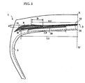
- FIG. 1 On the figure 1 , is shown a partial schematic view in meridian section of a tire 1 of dimension 315 / 80.R22.5 X.
- the tire 1 has an aspect ratio H / S substantially equal to 0.65, H being the height of the tire on rim and S the axial width maximum of said tire mounted on its service rim 9.00 x 22.5 and inflated to a recommended pressure of 9 bar.
- FIGS. 1 to 3 represent only half a view of the tires which extend symmetrically with respect to the axis XX 'which represents the circumferential median plane, or equatorial plane, of a tire.
- the axial width L 1 of the first working ply 31 is equal to 236 mm, when the tire is mounted on its service rim and inflated to its recommended pressure, which is, for a tire of usual shape less than the width of the tire. the tread, which is equal, in the case studied, to 242 mm.
- the axial width L 2 of the second working ply 32 is smaller than the width L 1 , since it is equal to 216 mm.
- the axial width L 0 of a triangulation half-ply 30 is equal to 70 mm and its axially outer end is at an axial distance from the equatorial plane equal to 100 mm.
- the two working plies 31 and 32 respectively have calenders C 1 and C 2 made of the same rubber mix. It is understood that the calendering could be different.
- the combination of the layers of rubber mix P and G ensures a decoupling between the working ply 31 and the end of the radially outer working ply 32.
- the zone of engagement of the rubber mix profiles P and G between the two working plies 31 and 32 is defined by the thickness or more precisely the radial distance d between the end of the ply 32 and the ply 31 and by the axial width D of the rubber mix profile G between the axially inner end of said rubber mix profile G and the end of the axially narrowest working crown ply 32.
- the radial distance d is equal to 3.5 mm.
- the axial distance D is equal to 21 mm, ie approximately 14 times the diameter ⁇ 2 of the reinforcing elements of the working ply 32, the diameter ⁇ 2 being equal to 1.5 mm.
- the modulus of elasticity at 10% elongation of the layers of rubber mix P and G and of the calendering layer C 2 of the working ply 32, respectively MP and MG and MC 2 , are chosen such that they satisfy the following relation: MP ⁇ MG ⁇ MC 2 .
- Such an embodiment of the tire 3 allows a reduction of the stresses of the calender layer C 2 , passing through the layer of rubber mix G in contact with the working ply 32 to the layer of rubber mix P in contact with the ply 31, which improves the resistance of the top architecture to the separation between the ends of the working plies 31 and 32.
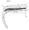
- the figure 2 represents a schematic view in meridian section of a tire 4, similar to that of the figure 1 which differs from the latter by the absence of a layer of rubber mix B and the presence of a layer of rubbery mixture G which envelope the end of the working ply 31 and extends radially inside said working crown ply.
- the layer of rubber mix G in addition to its decoupling function between the two working crown plies 31 and 32, fulfills the function of the layer of rubber mix B of the first embodiment. of the invention shown on the figure 1 .
- the figure 3 represents a schematic view in meridian section of a tire 5, similar to that of the figure 1 which differs from the latter by the presence of a complementary protective ply 33.
- the protective ply 33 is placed radially outside the working ply 32.
- the protective ply 33 is a sheet of wire ropes made of metal.
- so-called elastic steel that is to say having under a force equal to 10% of the tensile strength a relative elongation of at least 2% (while an elongation of less than 2% is the characteristic of a inextensible cable), oriented with respect to the circumferential direction of an angle ⁇ 3 in the same direction as the angle ⁇ 2 , but greater in absolute value at said angle ⁇ 2 of 8 ° since equal to 26 °.
- the width L 3 of the protective ply 33 is greater than the width L 2 of the working ply 32 the least wide and radially adjacent, and equal to 260 mm and therefore less than the width L 1 .
- the combination of the rubber mixers P and G leads to a decoupling of the axially widest working ply 31 and the end of the protective crown ply 33.
- the modulus of elasticity at 10% elongation of the layers of rubber mix P and G and of the caliper layer C 3 of the protective ply 33, respectively MP and MG and MC 3 are chosen as they satisfy. the following relation: MP ⁇ MG ⁇ MC 3 .
- the calendering C 3 of the protective crown ply 33 may be either identical to or different from one and / or the other of the calenders C 1 , C 2 of the working crown plies 31 and 32.
- Such an embodiment of the tire 5 allows a reduction of the stresses of the calender layer C 3 , passing through the layer of rubber mix G in contact with the protective layer 33 to the layer of rubber mix P in contact with the web 31, which makes it possible to improve the resistance of the top architecture to the separation between the ends of the working ply 31 and the protective ply 33.
- the optimum solution consists, according to the invention, in that the axially inner end of the layer of rubber mix G is maintained between the working crown plies 31 and 32 to maintain a decoupling between the working crown ply. 31 and the end of the working crown ply 32.
- the axially inner end of the first rubber compound profile P is located at a distance from the equatorial plane at least equal to the half-width of the working ply 32 axially the least wide.
- the comparative tests of the tires were carried out on the one hand on the motorway circuit, that is to say a circuit where the percentage of straight lines traveled is very important, and on the other hand, on a so-called high drift circuit, that is to say a circuit where the percentage of curves is the most important, load conditions and inflation pressure being the same for both runs and those recommended by the tire manufacturers.
- results obtained show an average advantage of 20% in kilometers of the tires made according to the invention and which does not comprise the third rubber mix profile B, compared to the reference tires in which the edges of the working plies 31 and 32 are separated by a single profile of rubber mix.
- the tires made according to the illustration of the figure 1 have an average advantage of 10% in kilometers compared to the tires made according to the invention and which does not include the third profile of rubber mix B.
- the presence of the third rubber compound profile B bordering the end of the sheet of radially innermost working reinforcing elements makes it possible to further limit the propagation of cracks at the ends of the plies of the plywood. crown frame.
Landscapes
- Engineering & Computer Science (AREA)
- Mechanical Engineering (AREA)
- Tires In General (AREA)
Applications Claiming Priority (3)
| Application Number | Priority Date | Filing Date | Title |
|---|---|---|---|
| FR0301904 | 2003-02-17 | ||
| FR0301904 | 2003-02-17 | ||
| PCT/EP2004/001362 WO2004076204A1 (fr) | 2003-02-17 | 2004-02-13 | Armature de sommet pour pneumatique radial |
Publications (2)
| Publication Number | Publication Date |
|---|---|
| EP1597094A1 EP1597094A1 (fr) | 2005-11-23 |
| EP1597094B1 true EP1597094B1 (fr) | 2009-05-06 |
Family
ID=32922201
Family Applications (1)
| Application Number | Title | Priority Date | Filing Date |
|---|---|---|---|
| EP04710851A Expired - Lifetime EP1597094B1 (fr) | 2003-02-17 | 2004-02-13 | Armature de sommet pour pneumatique radial |
Country Status (8)
| Country | Link |
|---|---|
| US (1) | US7243695B2 (enExample) |
| EP (1) | EP1597094B1 (enExample) |
| JP (1) | JP4689593B2 (enExample) |
| CN (1) | CN1750944B (enExample) |
| AT (1) | ATE430663T1 (enExample) |
| BR (1) | BRPI0407522A (enExample) |
| DE (1) | DE602004020973D1 (enExample) |
| WO (1) | WO2004076204A1 (enExample) |
Families Citing this family (58)
| Publication number | Priority date | Publication date | Assignee | Title |
|---|---|---|---|---|
| KR100563728B1 (ko) * | 2004-11-15 | 2006-03-28 | 한국타이어 주식회사 | 벨트 내구성을 향상시킨 중하중용 공기입 타이어 |
| FR2887818A1 (fr) | 2005-06-30 | 2007-01-05 | Michelin Soc Tech | Pneumatique pour vehicules lourds |
| FR2887817A1 (fr) | 2005-06-30 | 2007-01-05 | Michelin Soc Tech | Pneumatique pour vehicules lourds |
| FR2887816A1 (fr) * | 2005-06-30 | 2007-01-05 | Michelin Soc Tech | Pneumatique pour vehicules lourds |
| FR2887807A1 (fr) * | 2005-06-30 | 2007-01-05 | Michelin Soc Tech | Pneumatique pour vehicules lourds |
| FR2887814A1 (fr) * | 2005-06-30 | 2007-01-05 | Michelin Soc Tech | Pneumatique pour vehicules lourds |
| FR2887813A1 (fr) * | 2005-06-30 | 2007-01-05 | Michelin Soc Tech | Pneumatique pour vehicules lourds |
| FR2887810A1 (fr) | 2005-06-30 | 2007-01-05 | Michelin Soc Tech | Pneumatique pour vehicules lourds |
| FR2887812A1 (fr) * | 2005-06-30 | 2007-01-05 | Michelin Soc Tech | Pneumatique pour vehicules lourds |
| FR2887815A1 (fr) | 2005-06-30 | 2007-01-05 | Michelin Soc Tech | Pneumatique pour vehicules lourds |
| FR2887811A1 (fr) * | 2005-06-30 | 2007-01-05 | Michelin Soc Tech | Pneumatique pour vehicules lourds |
| FR2907373B1 (fr) * | 2006-10-18 | 2009-01-16 | Michelin Soc Tech | Pneumatique pour engin lourd |
| DE102011000821A1 (de) * | 2011-02-18 | 2012-08-23 | Continental Reifen Deutschland Gmbh | Fahrzeugluftreifen in Radialbauart für Nutzfahrzeuge |
| FR2981297B1 (fr) | 2011-10-13 | 2013-10-25 | Michelin Soc Tech | Pneumatique comportant une couche d'elements de renforcement circonferentiels |
| FR2981299B1 (fr) | 2011-10-13 | 2014-07-11 | Michelin Soc Tech | Pneumatique comportant une couche d'elements de renforcement circonferentiels |
| FR2981298B1 (fr) * | 2011-10-13 | 2014-05-02 | Soc Tech Michelin | Pneumatique comportant une couche d'elements de renforcement circonferentiels |
| FR2983778B1 (fr) | 2011-12-09 | 2014-08-01 | Michelin Soc Tech | Pneumatique comportant une couche d'elements de renforcement circonferentiels |
| FR2983777B1 (fr) | 2011-12-09 | 2014-03-07 | Michelin Soc Tech | Pneumatique comportant une couche d'elements de renforcement circonferentiels |
| ITRM20120584A1 (it) * | 2012-11-21 | 2014-05-22 | Bridgestone Corp | Pneumatico per uso agricolo |
| CN105829130A (zh) * | 2013-12-24 | 2016-08-03 | 普利司通美国轮胎运营有限责任公司 | 具有环绕在胶条上的带束层的轮胎 |
| FR3022845B1 (fr) | 2014-06-26 | 2016-06-10 | Michelin & Cie | Pneumatique comportant une couche d'elements de renforcement circonferentiels |
| FR3022840B1 (fr) | 2014-06-26 | 2016-06-10 | Michelin & Cie | Pneumatique comportant une couche d'elements de renforcement circonferentiels |
| FR3022846B1 (fr) | 2014-06-26 | 2016-06-10 | Michelin & Cie | Pneumatique comportant une couche d'elements de renforcement circonferentiels |
| FR3022844A1 (fr) | 2014-06-26 | 2016-01-01 | Michelin & Cie | Pneumatique comportant une couche d'elements de renforcement circonferentiels |
| FR3022843B1 (fr) | 2014-06-26 | 2017-11-24 | Michelin & Cie | Pneumatique comportant une couche d'elements de renforcement circonferentiels |
| FR3022841B1 (fr) | 2014-06-26 | 2016-06-10 | Michelin & Cie | Pneumatique comportant une couche d'elements de renforcement circonferentiels |
| FR3022842B1 (fr) | 2014-06-26 | 2016-06-10 | Michelin & Cie | Pneumatique comportant une couche d'elements de renforcement circonferentiels |
| FR3022838B1 (fr) | 2014-06-26 | 2016-06-10 | Michelin & Cie | Pneumatique comportant une couche d'elements de renforcement circonferentiels |
| FR3022839B1 (fr) | 2014-06-26 | 2017-11-24 | Michelin & Cie | Pneumatique comportant une couche d'elements de renforcement circonferentiels |
| FR3022848B1 (fr) | 2014-06-26 | 2016-06-10 | Michelin & Cie | Pneumatique presentant des proprietes dynamiques ameliorees |
| FR3051398A1 (fr) | 2016-05-20 | 2017-11-24 | Michelin & Cie | Pneumatique presentant une couche de protection avec des proprietes d’endurance ameliorees |
| FR3051399B1 (fr) | 2016-05-20 | 2018-05-11 | Compagnie Generale Des Etablissements Michelin | Pneumatique presentant une couche de protection avec des proprietes d’endurance ameliorees |
| FR3051397B1 (fr) | 2016-05-20 | 2018-05-11 | Compagnie Generale Des Etablissements Michelin | Pneumatique presentant une couche de protection avec des proprietes d’endurance ameliorees |
| WO2019197763A1 (fr) | 2018-04-09 | 2019-10-17 | Compagnie Generale Des Etablissements Michelin | Pneumatique allege comportant une couche d'elements de renforcement circonferentiels |
| WO2019197765A1 (fr) | 2018-04-09 | 2019-10-17 | Compagnie Generale Des Etablissements Michelin | Pneumatique presentant des proprietes de resistance au roulement et de resistance aux chocs ameliorees |
| FR3089877A3 (fr) | 2018-12-13 | 2020-06-19 | Michelin & Cie | Pneumatique presentant des proprietes de resistance au roulement et de resistance aux chocs ameliorees |
| FR3089997A3 (fr) | 2018-12-14 | 2020-06-19 | Michelin & Cie | Pneumatique allege comportant une couche d’elements de renforcement circonferentiels |
| WO2019197764A1 (fr) | 2018-04-09 | 2019-10-17 | Compagnie Generale Des Etablissements Michelin | Pneumatique presentant des proprietes de resistance au roulement et de resistance aux chocs ameliorees |
| FR3102096B1 (fr) | 2019-10-22 | 2021-09-17 | Michelin & Cie | Armature de sommet pour pneumatique de type metropolitain |
| FR3121634B1 (fr) | 2021-04-12 | 2025-02-28 | Michelin & Cie | Pneumatique allege comportant une couche d’elements de renforcement circonferentiels |
| FR3121635A1 (fr) | 2021-04-12 | 2022-10-14 | Compagnie Generale Des Etablissements Michelin | Pneumatique allege comportant une couche d’elements de renforcement circonferentiels |
| FR3136401B1 (fr) | 2022-06-09 | 2024-06-28 | Michelin & Cie | Pneumatique comprenant une armature de sommet a renforts metalliques trancannee |
| FR3143430B1 (fr) | 2022-12-16 | 2025-10-03 | Michelin & Cie | Pneumatique dont les performances d’endurance sont améliorées |
| FR3143432B1 (fr) | 2022-12-16 | 2025-10-03 | Michelin & Cie | Pneumatique allégé comportant une couche d’éléments de renforcement circonférentiels |
| FR3143431B1 (fr) | 2022-12-16 | 2025-10-03 | Michelin & Cie | Pneumatique dont les performances d’endurance sont améliorées |
| FR3143425A1 (fr) | 2022-12-16 | 2024-06-21 | Compagnie Generale Des Etablissements Michelin | Pneumatique allege |
| FR3143435A1 (fr) | 2022-12-16 | 2024-06-21 | Compagnie Generale Des Etablissements Michelin | Pneumatique comportant une couche d’éléments de renforcement circonférentiels |
| FR3143433A1 (fr) | 2022-12-16 | 2024-06-21 | Compagnie Generale Des Etablissements Michelin | Pneumatique allégé |
| FR3143434B1 (fr) | 2022-12-16 | 2025-10-03 | Michelin & Cie | Pneumatique comportant une couche d’éléments de renforcement circonférentiels |
| FR3143424A1 (fr) | 2022-12-16 | 2024-06-21 | Compagnie Generale Des Etablissements Michelin | Pneumatique allégé comportant une couche d’éléments de renforcement circonférentiels |
| FR3148166B1 (fr) | 2023-04-27 | 2025-03-14 | Michelin & Cie | Pneumatique dont la bande de roulement presente des proprietes d’endurance ameliorees |
| WO2024223572A1 (fr) | 2023-04-27 | 2024-10-31 | Compagnie Generale Des Etablissements Michelin | Pneumatique dont la bande de roulement presente des proprietes d'endurance ameliorees |
| CN121100067A (zh) | 2023-04-27 | 2025-12-09 | 米其林集团总公司 | 胎面具有改进的耐久性质的轮胎 |
| FR3148167B1 (fr) | 2023-04-27 | 2025-03-14 | Michelin & Cie | Pneumatique dont la bande de roulement presente des proprietes d’endurance ameliorees |
| WO2024223565A1 (fr) | 2023-04-27 | 2024-10-31 | Compagnie Generale Des Etablissements Michelin | Pneumatique dont la bande de roulement presente des proprietes d'endurance ameliorees |
| WO2024223571A1 (fr) | 2023-04-27 | 2024-10-31 | Compagnie Generale Des Etablissements Michelin | Pneumatique dont la bande de roulement presente des proprietes d'endurance ameliorees |
| FR3148165B1 (fr) | 2023-04-27 | 2025-03-14 | Michelin & Cie | Pneumatique dont la bande de roulement presente des proprietes d’endurance ameliorees |
| WO2024223566A1 (fr) | 2023-04-27 | 2024-10-31 | Compagnie Generale Des Etablissements Michelin | Pneumatique dont la bande de roulement presente des proprietes d'endurance ameliorees |
Family Cites Families (7)
| Publication number | Priority date | Publication date | Assignee | Title |
|---|---|---|---|---|
| JPH04252705A (ja) * | 1990-12-26 | 1992-09-08 | Yokohama Rubber Co Ltd:The | 重荷重用空気入りラジアルタイヤ |
| US5605589A (en) * | 1995-03-06 | 1997-02-25 | The Goodyear Tire & Rubber Company | Pneumatic tire with specified spacing between cords of inner and outer belts |
| JP3679213B2 (ja) * | 1996-01-22 | 2005-08-03 | 株式会社ブリヂストン | 重荷重用空気入りラジアルタイヤ |
| FR2765151A1 (fr) * | 1997-06-26 | 1999-01-01 | Michelin & Cie | Armature de sommet pour pneumatique radial |
| FR2774333B1 (fr) * | 1998-02-05 | 2000-03-03 | Michelin & Cie | Pneumatique a armature de sommet triangulee |
| JP3876085B2 (ja) * | 1998-12-18 | 2007-01-31 | 横浜ゴム株式会社 | 重荷重用空気入りラジアルタイヤ |
| JP4629655B2 (ja) * | 2003-02-17 | 2011-02-09 | ソシエテ ド テクノロジー ミシュラン | ラジアルタイヤ用クラウン補強体 |
-
2004
- 2004-02-13 WO PCT/EP2004/001362 patent/WO2004076204A1/fr not_active Ceased
- 2004-02-13 JP JP2006501835A patent/JP4689593B2/ja not_active Expired - Fee Related
- 2004-02-13 AT AT04710851T patent/ATE430663T1/de not_active IP Right Cessation
- 2004-02-13 CN CN2004800043410A patent/CN1750944B/zh not_active Expired - Fee Related
- 2004-02-13 DE DE602004020973T patent/DE602004020973D1/de not_active Expired - Lifetime
- 2004-02-13 EP EP04710851A patent/EP1597094B1/fr not_active Expired - Lifetime
- 2004-02-13 BR BRPI0407522-6A patent/BRPI0407522A/pt not_active Application Discontinuation
-
2005
- 2005-08-11 US US11/201,869 patent/US7243695B2/en not_active Expired - Lifetime
Also Published As
| Publication number | Publication date |
|---|---|
| ATE430663T1 (de) | 2009-05-15 |
| BRPI0407522A (pt) | 2006-02-14 |
| EP1597094A1 (fr) | 2005-11-23 |
| US7243695B2 (en) | 2007-07-17 |
| JP2006517887A (ja) | 2006-08-03 |
| DE602004020973D1 (de) | 2009-06-18 |
| CN1750944B (zh) | 2011-08-17 |
| US20060180257A1 (en) | 2006-08-17 |
| JP4689593B2 (ja) | 2011-05-25 |
| CN1750944A (zh) | 2006-03-22 |
| WO2004076204A1 (fr) | 2004-09-10 |
Similar Documents
| Publication | Publication Date | Title |
|---|---|---|
| EP1597094B1 (fr) | Armature de sommet pour pneumatique radial | |
| EP1648717B1 (fr) | Pneumatique pour vehicules lourds | |
| EP1648718B1 (fr) | Pneumatique pour vehicules lourds | |
| EP1597095B1 (fr) | Armature de sommet pour pneumatique radial | |
| EP2079596B1 (fr) | Pneumatique pour engin lourd | |
| EP3655262B1 (fr) | Pneumatique allege | |
| EP3484726A1 (fr) | Pneumatique dont la zone du bourrelet est allégée | |
| FR2887807A1 (fr) | Pneumatique pour vehicules lourds | |
| WO1999058351A1 (fr) | Armature de sommet de pneumatique radial | |
| FR3050962A1 (fr) | Pneumatique dont la zone du bourrelet est allegee | |
| EP3484728B1 (fr) | Pneumatique dont la zone du bourrelet est allegee | |
| EP3390079B1 (fr) | Pneumatique presentant des proprietes d'usure ameliorees | |
| EP3390076B1 (fr) | Pneumatique présentant des propriétés d'usure améliorées | |
| WO2018050988A1 (fr) | Pneumatique comportant trois couches de travail | |
| EP1899178B1 (fr) | Pneumatique pour vehicules lourds | |
| EP1899182B1 (fr) | Pneumatique pour vehicules lourds | |
| EP3390077B1 (fr) | Pneumatique presentant des proprietes d'usure ameliorees | |
| EP3390105B1 (fr) | Pneumatique présentant des propriétés d'usure améliorées | |
| FR3050961A1 (fr) | Pneumatique dont la zone du bourrelet est allegee | |
| EP4048528B1 (fr) | Armature de sommet pour pneumatique de type metropolitain | |
| EP4065384B1 (fr) | Armature de sommet de pneumatique constituee de deux couches de sommet de travail et d'une couche d'elements de renforcement circonferentiels | |
| WO2018172691A1 (fr) | Armature de sommet de pneumatique constituee d'une couche de sommet de travail et d'une couche d'elements circonferentiels | |
| CA3003081C (fr) | Pneumatique presentant des proprietes d'usure ameliorees | |
| EP3390078B1 (fr) | Pneumatique presentant des proprietes d'usure ameliorees | |
| EP1899177A1 (fr) | Pneumatique pour vehicules lourds |
Legal Events
| Date | Code | Title | Description |
|---|---|---|---|
| PUAI | Public reference made under article 153(3) epc to a published international application that has entered the european phase |
Free format text: ORIGINAL CODE: 0009012 |
|
| 17P | Request for examination filed |
Effective date: 20050919 |
|
| AK | Designated contracting states |
Kind code of ref document: A1 Designated state(s): AT BE BG CH CY CZ DE DK EE ES FI FR GB GR HU IE IT LI LU MC NL PT RO SE SI SK TR |
|
| AX | Request for extension of the european patent |
Extension state: AL LT LV MK |
|
| DAX | Request for extension of the european patent (deleted) | ||
| 17Q | First examination report despatched |
Effective date: 20070711 |
|
| GRAP | Despatch of communication of intention to grant a patent |
Free format text: ORIGINAL CODE: EPIDOSNIGR1 |
|
| GRAS | Grant fee paid |
Free format text: ORIGINAL CODE: EPIDOSNIGR3 |
|
| GRAA | (expected) grant |
Free format text: ORIGINAL CODE: 0009210 |
|
| AK | Designated contracting states |
Kind code of ref document: B1 Designated state(s): AT BE BG CH CY CZ DE DK EE ES FI FR GB GR HU IE IT LI LU MC NL PT RO SE SI SK TR |
|
| REG | Reference to a national code |
Ref country code: GB Ref legal event code: FG4D Free format text: NOT ENGLISH |
|
| REG | Reference to a national code |
Ref country code: CH Ref legal event code: EP |
|
| REG | Reference to a national code |
Ref country code: IE Ref legal event code: FG4D |
|
| REF | Corresponds to: |
Ref document number: 602004020973 Country of ref document: DE Date of ref document: 20090618 Kind code of ref document: P |
|
| PG25 | Lapsed in a contracting state [announced via postgrant information from national office to epo] |
Ref country code: PT Free format text: LAPSE BECAUSE OF FAILURE TO SUBMIT A TRANSLATION OF THE DESCRIPTION OR TO PAY THE FEE WITHIN THE PRESCRIBED TIME-LIMIT Effective date: 20090906 Ref country code: FI Free format text: LAPSE BECAUSE OF FAILURE TO SUBMIT A TRANSLATION OF THE DESCRIPTION OR TO PAY THE FEE WITHIN THE PRESCRIBED TIME-LIMIT Effective date: 20090506 Ref country code: AT Free format text: LAPSE BECAUSE OF FAILURE TO SUBMIT A TRANSLATION OF THE DESCRIPTION OR TO PAY THE FEE WITHIN THE PRESCRIBED TIME-LIMIT Effective date: 20090506 Ref country code: ES Free format text: LAPSE BECAUSE OF FAILURE TO SUBMIT A TRANSLATION OF THE DESCRIPTION OR TO PAY THE FEE WITHIN THE PRESCRIBED TIME-LIMIT Effective date: 20090817 |
|
| PG25 | Lapsed in a contracting state [announced via postgrant information from national office to epo] |
Ref country code: SE Free format text: LAPSE BECAUSE OF FAILURE TO SUBMIT A TRANSLATION OF THE DESCRIPTION OR TO PAY THE FEE WITHIN THE PRESCRIBED TIME-LIMIT Effective date: 20090806 Ref country code: SI Free format text: LAPSE BECAUSE OF FAILURE TO SUBMIT A TRANSLATION OF THE DESCRIPTION OR TO PAY THE FEE WITHIN THE PRESCRIBED TIME-LIMIT Effective date: 20090506 |
|
| REG | Reference to a national code |
Ref country code: IE Ref legal event code: FD4D |
|
| PG25 | Lapsed in a contracting state [announced via postgrant information from national office to epo] |
Ref country code: CZ Free format text: LAPSE BECAUSE OF FAILURE TO SUBMIT A TRANSLATION OF THE DESCRIPTION OR TO PAY THE FEE WITHIN THE PRESCRIBED TIME-LIMIT Effective date: 20090506 Ref country code: RO Free format text: LAPSE BECAUSE OF FAILURE TO SUBMIT A TRANSLATION OF THE DESCRIPTION OR TO PAY THE FEE WITHIN THE PRESCRIBED TIME-LIMIT Effective date: 20090506 Ref country code: DK Free format text: LAPSE BECAUSE OF FAILURE TO SUBMIT A TRANSLATION OF THE DESCRIPTION OR TO PAY THE FEE WITHIN THE PRESCRIBED TIME-LIMIT Effective date: 20090506 Ref country code: IE Free format text: LAPSE BECAUSE OF FAILURE TO SUBMIT A TRANSLATION OF THE DESCRIPTION OR TO PAY THE FEE WITHIN THE PRESCRIBED TIME-LIMIT Effective date: 20090506 Ref country code: EE Free format text: LAPSE BECAUSE OF FAILURE TO SUBMIT A TRANSLATION OF THE DESCRIPTION OR TO PAY THE FEE WITHIN THE PRESCRIBED TIME-LIMIT Effective date: 20090506 |
|
| PG25 | Lapsed in a contracting state [announced via postgrant information from national office to epo] |
Ref country code: SK Free format text: LAPSE BECAUSE OF FAILURE TO SUBMIT A TRANSLATION OF THE DESCRIPTION OR TO PAY THE FEE WITHIN THE PRESCRIBED TIME-LIMIT Effective date: 20090506 |
|
| PLBE | No opposition filed within time limit |
Free format text: ORIGINAL CODE: 0009261 |
|
| STAA | Information on the status of an ep patent application or granted ep patent |
Free format text: STATUS: NO OPPOSITION FILED WITHIN TIME LIMIT |
|
| PG25 | Lapsed in a contracting state [announced via postgrant information from national office to epo] |
Ref country code: BG Free format text: LAPSE BECAUSE OF FAILURE TO SUBMIT A TRANSLATION OF THE DESCRIPTION OR TO PAY THE FEE WITHIN THE PRESCRIBED TIME-LIMIT Effective date: 20090806 |
|
| 26N | No opposition filed |
Effective date: 20100209 |
|
| BERE | Be: lapsed |
Owner name: MICHELIN RECHERCHE ET TECHNIQUE S.A. Effective date: 20100228 Owner name: SOC. DE TECHNOLOGIE MICHELIN Effective date: 20100228 |
|
| REG | Reference to a national code |
Ref country code: CH Ref legal event code: PL |
|
| GBPC | Gb: european patent ceased through non-payment of renewal fee |
Effective date: 20100213 |
|
| PG25 | Lapsed in a contracting state [announced via postgrant information from national office to epo] |
Ref country code: MC Free format text: LAPSE BECAUSE OF NON-PAYMENT OF DUE FEES Effective date: 20100301 Ref country code: GR Free format text: LAPSE BECAUSE OF FAILURE TO SUBMIT A TRANSLATION OF THE DESCRIPTION OR TO PAY THE FEE WITHIN THE PRESCRIBED TIME-LIMIT Effective date: 20090807 Ref country code: CH Free format text: LAPSE BECAUSE OF NON-PAYMENT OF DUE FEES Effective date: 20100228 Ref country code: LI Free format text: LAPSE BECAUSE OF NON-PAYMENT OF DUE FEES Effective date: 20100228 |
|
| PG25 | Lapsed in a contracting state [announced via postgrant information from national office to epo] |
Ref country code: BE Free format text: LAPSE BECAUSE OF NON-PAYMENT OF DUE FEES Effective date: 20100228 |
|
| PG25 | Lapsed in a contracting state [announced via postgrant information from national office to epo] |
Ref country code: GB Free format text: LAPSE BECAUSE OF NON-PAYMENT OF DUE FEES Effective date: 20100213 |
|
| PGFP | Annual fee paid to national office [announced via postgrant information from national office to epo] |
Ref country code: IT Payment date: 20120221 Year of fee payment: 9 |
|
| PG25 | Lapsed in a contracting state [announced via postgrant information from national office to epo] |
Ref country code: CY Free format text: LAPSE BECAUSE OF FAILURE TO SUBMIT A TRANSLATION OF THE DESCRIPTION OR TO PAY THE FEE WITHIN THE PRESCRIBED TIME-LIMIT Effective date: 20090506 |
|
| PG25 | Lapsed in a contracting state [announced via postgrant information from national office to epo] |
Ref country code: HU Free format text: LAPSE BECAUSE OF FAILURE TO SUBMIT A TRANSLATION OF THE DESCRIPTION OR TO PAY THE FEE WITHIN THE PRESCRIBED TIME-LIMIT Effective date: 20091107 Ref country code: LU Free format text: LAPSE BECAUSE OF NON-PAYMENT OF DUE FEES Effective date: 20100213 |
|
| PG25 | Lapsed in a contracting state [announced via postgrant information from national office to epo] |
Ref country code: TR Free format text: LAPSE BECAUSE OF FAILURE TO SUBMIT A TRANSLATION OF THE DESCRIPTION OR TO PAY THE FEE WITHIN THE PRESCRIBED TIME-LIMIT Effective date: 20090506 |
|
| PG25 | Lapsed in a contracting state [announced via postgrant information from national office to epo] |
Ref country code: IT Free format text: LAPSE BECAUSE OF NON-PAYMENT OF DUE FEES Effective date: 20130213 |
|
| REG | Reference to a national code |
Ref country code: FR Ref legal event code: PLFP Year of fee payment: 13 |
|
| REG | Reference to a national code |
Ref country code: FR Ref legal event code: PLFP Year of fee payment: 14 |
|
| REG | Reference to a national code |
Ref country code: FR Ref legal event code: PLFP Year of fee payment: 15 |
|
| PGFP | Annual fee paid to national office [announced via postgrant information from national office to epo] |
Ref country code: NL Payment date: 20190218 Year of fee payment: 16 |
|
| PGFP | Annual fee paid to national office [announced via postgrant information from national office to epo] |
Ref country code: DE Payment date: 20190219 Year of fee payment: 16 |
|
| REG | Reference to a national code |
Ref country code: DE Ref legal event code: R119 Ref document number: 602004020973 Country of ref document: DE |
|
| REG | Reference to a national code |
Ref country code: NL Ref legal event code: MM Effective date: 20200301 |
|
| PG25 | Lapsed in a contracting state [announced via postgrant information from national office to epo] |
Ref country code: NL Free format text: LAPSE BECAUSE OF NON-PAYMENT OF DUE FEES Effective date: 20200301 |
|
| PG25 | Lapsed in a contracting state [announced via postgrant information from national office to epo] |
Ref country code: DE Free format text: LAPSE BECAUSE OF NON-PAYMENT OF DUE FEES Effective date: 20200901 |
|
| PGFP | Annual fee paid to national office [announced via postgrant information from national office to epo] |
Ref country code: FR Payment date: 20230220 Year of fee payment: 20 |