EP1597007B2 - Porte-outil - Google Patents
Porte-outil Download PDFInfo
- Publication number
- EP1597007B2 EP1597007B2 EP04713001.8A EP04713001A EP1597007B2 EP 1597007 B2 EP1597007 B2 EP 1597007B2 EP 04713001 A EP04713001 A EP 04713001A EP 1597007 B2 EP1597007 B2 EP 1597007B2
- Authority
- EP
- European Patent Office
- Prior art keywords
- sleeve
- tube element
- clamping chuck
- tool
- adjusting screw
- Prior art date
- Legal status (The legal status is an assumption and is not a legal conclusion. Google has not performed a legal analysis and makes no representation as to the accuracy of the status listed.)
- Expired - Lifetime
Links
- 230000008878 coupling Effects 0.000 claims description 10
- 238000010168 coupling process Methods 0.000 claims description 10
- 238000005859 coupling reaction Methods 0.000 claims description 10
- 238000001816 cooling Methods 0.000 claims description 7
- 239000000463 material Substances 0.000 claims description 7
- 230000001050 lubricating effect Effects 0.000 claims description 6
- 239000002184 metal Substances 0.000 claims description 5
- 239000004033 plastic Substances 0.000 claims description 5
- 229920003023 plastic Polymers 0.000 claims description 5
- 239000011248 coating agent Substances 0.000 claims description 2
- 238000000576 coating method Methods 0.000 claims description 2
- 239000004918 carbon fiber reinforced polymer Substances 0.000 claims 1
- 229910010293 ceramic material Inorganic materials 0.000 claims 1
- 239000000314 lubricant Substances 0.000 description 9
- 239000002826 coolant Substances 0.000 description 7
- 238000003780 insertion Methods 0.000 description 7
- 230000037431 insertion Effects 0.000 description 7
- 238000013461 design Methods 0.000 description 4
- 230000015572 biosynthetic process Effects 0.000 description 3
- 238000010276 construction Methods 0.000 description 3
- 238000006073 displacement reaction Methods 0.000 description 3
- 230000005540 biological transmission Effects 0.000 description 2
- 238000011161 development Methods 0.000 description 2
- 230000018109 developmental process Effects 0.000 description 2
- 230000003993 interaction Effects 0.000 description 2
- 238000012423 maintenance Methods 0.000 description 2
- 239000000919 ceramic Substances 0.000 description 1
- 230000003247 decreasing effect Effects 0.000 description 1
- 230000001419 dependent effect Effects 0.000 description 1
- 230000001939 inductive effect Effects 0.000 description 1
- 238000009434 installation Methods 0.000 description 1
- 238000000034 method Methods 0.000 description 1
- 230000008569 process Effects 0.000 description 1
- 238000007789 sealing Methods 0.000 description 1
- 238000000926 separation method Methods 0.000 description 1
- 238000012546 transfer Methods 0.000 description 1
- 230000007704 transition Effects 0.000 description 1
- 230000032258 transport Effects 0.000 description 1
Images
Classifications
-
- B—PERFORMING OPERATIONS; TRANSPORTING
- B23—MACHINE TOOLS; METAL-WORKING NOT OTHERWISE PROVIDED FOR
- B23B—TURNING; BORING
- B23B27/00—Tools for turning or boring machines; Tools of a similar kind in general; Accessories therefor
- B23B27/14—Cutting tools of which the bits or tips or cutting inserts are of special material
-
- B—PERFORMING OPERATIONS; TRANSPORTING
- B23—MACHINE TOOLS; METAL-WORKING NOT OTHERWISE PROVIDED FOR
- B23Q—DETAILS, COMPONENTS, OR ACCESSORIES FOR MACHINE TOOLS, e.g. ARRANGEMENTS FOR COPYING OR CONTROLLING; MACHINE TOOLS IN GENERAL CHARACTERISED BY THE CONSTRUCTION OF PARTICULAR DETAILS OR COMPONENTS; COMBINATIONS OR ASSOCIATIONS OF METAL-WORKING MACHINES, NOT DIRECTED TO A PARTICULAR RESULT
- B23Q11/00—Accessories fitted to machine tools for keeping tools or parts of the machine in good working condition or for cooling work; Safety devices specially combined with or arranged in, or specially adapted for use in connection with, machine tools
- B23Q11/10—Arrangements for cooling or lubricating tools or work
- B23Q11/1015—Arrangements for cooling or lubricating tools or work by supplying a cutting liquid through the spindle
- B23Q11/1023—Tool holders, or tools in general specially adapted for receiving the cutting liquid from the spindle
-
- B—PERFORMING OPERATIONS; TRANSPORTING
- B23—MACHINE TOOLS; METAL-WORKING NOT OTHERWISE PROVIDED FOR
- B23B—TURNING; BORING
- B23B31/00—Chucks; Expansion mandrels; Adaptations thereof for remote control
- B23B31/02—Chucks
- B23B31/028—Chucks the axial positioning of the tool being adjustable
-
- B—PERFORMING OPERATIONS; TRANSPORTING
- B23—MACHINE TOOLS; METAL-WORKING NOT OTHERWISE PROVIDED FOR
- B23B—TURNING; BORING
- B23B31/00—Chucks; Expansion mandrels; Adaptations thereof for remote control
- B23B31/02—Chucks
- B23B31/24—Chucks characterised by features relating primarily to remote control of the gripping means
- B23B31/30—Chucks characterised by features relating primarily to remote control of the gripping means using fluid-pressure means in the chuck
- B23B31/305—Chucks characterised by features relating primarily to remote control of the gripping means using fluid-pressure means in the chuck the gripping means is a deformable sleeve
-
- B—PERFORMING OPERATIONS; TRANSPORTING
- B23—MACHINE TOOLS; METAL-WORKING NOT OTHERWISE PROVIDED FOR
- B23D—PLANING; SLOTTING; SHEARING; BROACHING; SAWING; FILING; SCRAPING; LIKE OPERATIONS FOR WORKING METAL BY REMOVING MATERIAL, NOT OTHERWISE PROVIDED FOR
- B23D23/00—Machines or devices for shearing or cutting profiled stock
-
- B—PERFORMING OPERATIONS; TRANSPORTING
- B23—MACHINE TOOLS; METAL-WORKING NOT OTHERWISE PROVIDED FOR
- B23Q—DETAILS, COMPONENTS, OR ACCESSORIES FOR MACHINE TOOLS, e.g. ARRANGEMENTS FOR COPYING OR CONTROLLING; MACHINE TOOLS IN GENERAL CHARACTERISED BY THE CONSTRUCTION OF PARTICULAR DETAILS OR COMPONENTS; COMBINATIONS OR ASSOCIATIONS OF METAL-WORKING MACHINES, NOT DIRECTED TO A PARTICULAR RESULT
- B23Q1/00—Members which are comprised in the general build-up of a form of machine, particularly relatively large fixed members
-
- B—PERFORMING OPERATIONS; TRANSPORTING
- B23—MACHINE TOOLS; METAL-WORKING NOT OTHERWISE PROVIDED FOR
- B23Q—DETAILS, COMPONENTS, OR ACCESSORIES FOR MACHINE TOOLS, e.g. ARRANGEMENTS FOR COPYING OR CONTROLLING; MACHINE TOOLS IN GENERAL CHARACTERISED BY THE CONSTRUCTION OF PARTICULAR DETAILS OR COMPONENTS; COMBINATIONS OR ASSOCIATIONS OF METAL-WORKING MACHINES, NOT DIRECTED TO A PARTICULAR RESULT
- B23Q11/00—Accessories fitted to machine tools for keeping tools or parts of the machine in good working condition or for cooling work; Safety devices specially combined with or arranged in, or specially adapted for use in connection with, machine tools
-
- Y—GENERAL TAGGING OF NEW TECHNOLOGICAL DEVELOPMENTS; GENERAL TAGGING OF CROSS-SECTIONAL TECHNOLOGIES SPANNING OVER SEVERAL SECTIONS OF THE IPC; TECHNICAL SUBJECTS COVERED BY FORMER USPC CROSS-REFERENCE ART COLLECTIONS [XRACs] AND DIGESTS
- Y10—TECHNICAL SUBJECTS COVERED BY FORMER USPC
- Y10T—TECHNICAL SUBJECTS COVERED BY FORMER US CLASSIFICATION
- Y10T279/00—Chucks or sockets
- Y10T279/17—Socket type
- Y10T279/17111—Fluid-conduit drill holding
-
- Y—GENERAL TAGGING OF NEW TECHNOLOGICAL DEVELOPMENTS; GENERAL TAGGING OF CROSS-SECTIONAL TECHNOLOGIES SPANNING OVER SEVERAL SECTIONS OF THE IPC; TECHNICAL SUBJECTS COVERED BY FORMER USPC CROSS-REFERENCE ART COLLECTIONS [XRACs] AND DIGESTS
- Y10—TECHNICAL SUBJECTS COVERED BY FORMER USPC
- Y10T—TECHNICAL SUBJECTS COVERED BY FORMER US CLASSIFICATION
- Y10T279/00—Chucks or sockets
- Y10T279/34—Accessory or component
- Y10T279/3487—Tool or work stop or locator
-
- Y—GENERAL TAGGING OF NEW TECHNOLOGICAL DEVELOPMENTS; GENERAL TAGGING OF CROSS-SECTIONAL TECHNOLOGIES SPANNING OVER SEVERAL SECTIONS OF THE IPC; TECHNICAL SUBJECTS COVERED BY FORMER USPC CROSS-REFERENCE ART COLLECTIONS [XRACs] AND DIGESTS
- Y10—TECHNICAL SUBJECTS COVERED BY FORMER USPC
- Y10T—TECHNICAL SUBJECTS COVERED BY FORMER US CLASSIFICATION
- Y10T408/00—Cutting by use of rotating axially moving tool
- Y10T408/44—Cutting by use of rotating axially moving tool with means to apply transient, fluent medium to work or product
-
- Y—GENERAL TAGGING OF NEW TECHNOLOGICAL DEVELOPMENTS; GENERAL TAGGING OF CROSS-SECTIONAL TECHNOLOGIES SPANNING OVER SEVERAL SECTIONS OF THE IPC; TECHNICAL SUBJECTS COVERED BY FORMER USPC CROSS-REFERENCE ART COLLECTIONS [XRACs] AND DIGESTS
- Y10—TECHNICAL SUBJECTS COVERED BY FORMER USPC
- Y10T—TECHNICAL SUBJECTS COVERED BY FORMER US CLASSIFICATION
- Y10T409/00—Gear cutting, milling, or planing
- Y10T409/30—Milling
- Y10T409/30952—Milling with cutter holder
Definitions
- the invention relates to a chuck for a tool according to the preamble of claim 1 or 5.
- the EP 1 127 656 B1 describes a chuck according to the preamble of claim 1 or 5, ie a tool holder for a machine tool, in which a connecting tube is slidably mounted and depending on the length of a tool to be used longitudinally adjustable in a lubricant receiving tube.
- such a chuck is known from TA 30 8243 01 of the company bielomatik LEUZE GmbH + Co, D-72637 Neuffen.
- This can also be used as a chuck for tools which must be held at different depths in the chuck and held for this purpose by means of a shrink connection or by means of a hydraulic expansion chuck.
- the pipe nozzle or the pipe element is guided longitudinally displaceable in the adjusting screw and the adjusting screw is also longitudinally adjustable by means of a turning key in the chuck, so that the screw on contact with the tensioned chuck tool can be rotated.
- the adjusting screw is also used for manually adjusting the insertion depth of the tool, whereby the pipe nozzle and the sleeve have to be temporarily removed for turning the adjusting screw.
- This temporary disassembly is also required if the insertion depth adjustment is carried out automatically by means of a lance (see, for example, inductive shrinking device GISS 3000 in the Guhring catalog: " Precision Cutting Tools "Edition 2002, page 958 ) to turn the adjusting screw after adjustment to contact with the tool, so that a swirling of the coolant or lubricant flow is avoided in a clearance between the set screw and the tool.
- a disadvantage of the prior art is thus the need to disassemble and assemble the arranged in the chuck coolant supply at each required for the tool adjustment process.
- the object of the invention is to propose a chuck, which simplifies or reduces the work steps during the first and repeated setting of the insertion depth of a tool.
- the chuck according to the invention has a tubular element, which is longitudinally displaceable in the sleeve, can be actuated at an end located in the sleeve by an adjusting tool and is positively and / or non-positively connected with the adjusting screw.
- This makes it possible to turn the adjusting screw, in particular in the formation of a suitable engagement on the tubular element directly by means of an adjusting tool, which cooperates through the sleeve with the intervention, with the interposition of the tubular element, without having to dismantle the tubular element and the sleeve.
- the screw can be rotated after an automated setting of the insertion depth of a tool which is made in a special device by means of a lance, without disassembly of the sleeve and pipe element to the tool. It is also possible with a manual adjustment of the insertion depth of the tool, in which instead of the lance, the screw serves as a stop for Einstecktiefenbetician the tool to rotate the adjustment without disassembly of the sleeve and the tubular element with the adjusting tool in the desired position.
- the user also has these advantages when the tool has to be readjusted as a result of the wear, that is, it has to be clamped with a different insertion depth.
- the invention provides for the pipe element to be glued to the adjusting screw or screwed against rotation or connected by a corresponding contour rotatably.
- tube elements of different lengths and / or different construction can be combined with the adjusting screw quickly.
- tubular element and the adjusting screw in one piece and in particular as a turned part.
- a one-piece design of pipe element and screw allows a particularly simple handling of the components, furthermore, here the transition of the arranged in the pipe element channel can be optimally designed on the bore of the screw after fluidic considerations.
- the adjusting tool engages through a channel of the sleeve into the engagement of the tubular element and in this case is rotatable in the channel. This allows easy adjustment of the set screw.
- An embodiment of the invention provides to store the tube member in the sleeve and / or in the screw longitudinally displaceable and to make the set screw for actuation by an adjusting tool, the adjusting tool can engage from the opposite side of the tool through the sleeve and the tube element and is freely rotatable relative to the sleeve and the tube element.
- the advantages already described are also achieved.
- the direct interaction of the Stelltechnikmaschines with the screw a torque transmission, which does not load the pipe element, so that it can be designed weaker and thus cheaper.
- an engagement for the adjusting tool is formed on the screw, for example.
- the sleeve and the tubular element integrally formed in order to reduce the number of small parts and to make the handling or installation of small parts easier.
- An expedient embodiment of the subject invention provides to seal the pipe nozzle relative to the sleeve. As a result, an undesirable loss of coolant or lubricant in spaces between the device and the chuck is avoided.
- a contact seal for sealing the tube element relative to the sleeve by means of a contact seal, lip seal or at least one O-ring, wherein the O-ring is mounted in the sleeve and / or on the tube element.
- a contact seal for sealing the tube element relative to the sleeve by means of a contact seal, lip seal or at least one O-ring, wherein the O-ring is mounted in the sleeve and / or on the tube element.
- an engagement on the pipe element or on the adjusting screw which in particular form a receptacle for a socket wrench, in particular a hexagonal wrench.
- a socket wrench is a particularly slim adjusting tool available, which is unerring inserted through the sleeve.
- the invention provides to provide the sleeve with an inner diameter, which tapers at least partially towards the tubular element.
- the coolant or lubricant flow is nozzle-like supplied to the pipe element to prevent the formation of vortices.
- An advantageous embodiment of the subject invention provides to screw the sleeve by means of a threaded sleeve or nut on the chuck. As a result, a secure, yet easily releasable connection is created, which allows easy maintenance of all components.
- the through hole of the adjusting screw to the tool in a funnel shape.
- a funnel-shaped opening to the tool out allows optimal flow and supply of running in the tool channels with coolant or lubricant.
- the invention further provides to form the sleeve, the tube element and the adjusting screw made of plastic and / or metal and / or ceramic and to provide the sleeve and / or the tube element and / or the adjusting screw with a coating. This makes it possible to optimally design the individual components to the requirements placed on them.
- the sleeve, the tube element and the adjusting screw are designed such that they can be penetrated by an adjusting bolt of an automatic device for adjusting the position of the tool, wherein the adjusting bolt can be moved in the direction of the longitudinal axis of the chuck, e.g. is displaceable for positioning a tool.
- the invention provides to rotate the pipe element directly or indirectly with the adjusting tool.
- An immediate adjustment allows the direct engagement with the adjusting tool in the tubular element and thus an accurate adjustability of the tubular element, since there is little play between the interacting components.
- the use of an adapter between the adjusting tool allows the formation of a special engagement in the tubular element with simultaneous applicability of standard tools as adjusting tool.
- the pipe element of sub-elements which consist of different materials, it is possible to optimally adapt the pipe element to different requirements, so that the pipe element can be constructed in the region of engagement for the adjusting tool in particular from a torsion-resistant material such as metal and in the field Front side, which rests on the tool during operation, made of plastic, to obtain a particularly good seal to the tool.
- the invention provides for coupling the tube element and the sleeve with one another in order to transmit a rotational movement introduced into the sleeve with the adjusting tool onto the tube element.
- the tube element is longitudinally displaceable relative to the sleeve, but the rotational movement of the sleeve is transmitted to the tube element.
- the sleeve is made of metal to ensure optimum interaction with the adjusting tool and the tubular element is made of plastic, in order to obtain an optimal sealing connection to the tool.
- drivers and guide slots in the sleeve or in the tubular element are to be dimensioned according to the material properties.
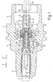
- a chuck 1 is shown in section.
- the chuck 1 has a longitudinal axis 1. Along the longitudinal axis 1 passes through a bore 2 of the chuck 1, which has sections of different diameters.
- the chuck 1 has a clamping section 3, a middle section 4 and a coupling section 5.
- the clamping section 3 is intended to receive a tool 6 (indicated by dashed lines), which has medium channels 7 for transporting cooling or lubricating medium to a tool tip, not shown, which open into a bottom surface 8.
- a device 9 for supplying a cooling or lubricating medium to the medium channels 7 of the tool 6 is arranged in the bore 2.
- the chuck 1 is designed as a so-called Hydrodehnspannfutter, in which the tool 6 is hydraulically tensioned, wherein the pressure on the tool 6 is generated via an annular channel 11 which lies in the clamping portion 3 of the chuck 1.
- the increasing and decreasing of the pressure via an adjusting screw (not shown) which is arranged in a bore 12.
- the device 9 consists essentially of a sleeve 13, a pipe section 14 and a screw 15, wherein the tubular element 14 and the adjusting screw 15 are integrally formed as a pipe screw 16.
- the sleeve 13 has a through hole 17.
- the sleeve 13 is provided with an annular shoulder 19 and has an O-ring seal 20 in the region of the through-bore 17.
- the threaded sleeve 21 exerts pressure on the shoulder 19 of the sleeve 13 and the shoulder 19 is supported via an O-ring seal 23 against the wall 22 from.
- the conduit 10 opens into the sleeve 13.
- the tubular element 14 is partially inserted into the sleeve 13 and is sealed relative to the sleeve 13 by the O-ring seal 20 mounted in the sleeve.
- a channel 26 formed by the tube member 14 is formed as an engagement 27 for an unillustrated adjusting tool.
- the channel 26 of the tubular element 14 merges in an oriented in the direction of the tool 6 end portion 28 in a channel 29, which passes through the integrally formed with the pipe member 14 screw 15 in the direction of the tool 6.
- the adjusting screw 15 is adjustably guided with an external thread G 15 in an internal thread G 2 of the bore 2, which passes through the chuck 1. From the in the FIG. 1 shown position, the pipe screw 16 in an arrow direction z on the tool 6 is adjustable. This adjustment or longitudinal displacement takes place with the aid of the adjusting tool, not shown, which engages in the receptacle formed by the engagement 27 for a socket wrench and the pipe screw 16 relative to the chuck 1 rotates in a rotational direction w about the longitudinal axis 1.
- the tubular element 14 of the pipe screw 16 is slowly pulled out of the sleeve 13 in this direction by the adjusting screw 15 in the arrow direction x, and the adjusting screw 15 moves toward the bottom surface 8 of the tool 6.
- the readjustment of the adjusting screw 15 or of the tubular element 14 is completed when an end face 30 of the adjusting screw 15 seals with the tool 6.
- the pipe screw 16 is displaced by a dimension a in the direction z, so that the pipe element 14 is not so deep in the sleeve 13 inserted.
- the device 9 allows for automatic adjustment of the clamping depth of the tool 6 a symbolically indicated lance 31 an automatic horriervorraum not shown through the sleeve 13, the tubular element 14 and the screw 15 to pass, so that it serves as a stop for the tool 6 , That is, the tool 6 is pushed in the relaxed state of the Hydrodehnspannfutters 1 to the lance 31 and then clamped in the hydraulic chuck 1, so that it is held in the specified by the lance clamping. Subsequently, the device 9 is adjusted so that the adjusting screw 15 contacts the tool 6.
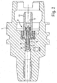
- Fig. 2 is that in Fig. 1 shown chuck 1 shown again, wherein the pipe screw 16 is formed in two parts.
- the pipe screw 16 here consists of a tubular element 14 which is inserted with an end portion 28 in a channel 29 of a screw 15 and glued to it.
- a rotation of a socket wrench which engages in an engagement 27 of the tubular element 14, causes a common rotation and displacement of the tubular element 14 and the adjusting screw 15.
- the tube member 14 has an O-ring seal 32 with which this in the through hole 17 of the sleeve 15 is movable.
- it is provided to provide an engagement for a socket wrench in the screw and to dimension the channel of the tubular element and the through hole of the sleeve so that the socket wrench can engage through it into the engagement.
- the invention is not limited to illustrated or described embodiments. Rather, it includes developments of the invention within the scope of the patent claims. In particular, it is provided in a multi-part design of adjusting screw and pipe element, pipe elements of different lengths ready to form chucks with different dimensions according to the invention can.
Landscapes
- Engineering & Computer Science (AREA)
- Mechanical Engineering (AREA)
- Gripping On Spindles (AREA)
- Auxiliary Devices For Machine Tools (AREA)
Claims (23)
- Mandrin de serrage (1) pour un outil (6) avec une section de serrage (3), une section centrale (4) et une section d'accouplement (5) réalisée comme HSK-cône creux, comportant un dispositif (9) d'amenée d'un agent réfrigérant et/ou lubrifiant à un canal pour fluide (7) de l'outil (6) maintenu dans le mandrin de serrage (1), un manchon (13) étant disposé dans le mandrin de serrage (1), lequel sert d'accouplement à une conduite d'amenée (10) pour l'alimentation en agent, un élément tubulaire (14) étant logé dans le manchon (13), en aval duquel est disposée une vis de réglage (15), la vis de réglage (15) étant déplaçable par rapport au mandrin de serrage (1) dans la direction de l'axe longitudinal (I) du mandrin de serrage (1), l'élément tubulaire (14) étant déplaçable dans le manchon (13) dans la direction de l'axe longitudinal (I) du mandrin de serrage (1) et une prise (27) réalisée comme une réception pour une clé à tube et étant formée dans l'élément tubulaire (14) ou la vis de réglage (15), caractérisé en ce que l'élément tubulaire (14) peut être actionné par la clé à tube sur le côté (25) opposé à l'outil (6), et en ce que l'élément tubulaire est raccordé de manière solidaire en rotation à la vis de réglage (15).
- Mandrin de serrage selon la revendication 1, caractérisé en ce que l'élément tubulaire (14) est collé et/ou vissé à la vis de réglage (15), et/ou présente un contour par rapport à la vis de réglage, lequel empêche une rotation de l'élément tubulaire (14) dans la vis de réglage.
- Mandrin de serrage selon l'une des revendications précédentes, caractérisé en ce que l'élément tubulaire (14) et la vis de réglage (15) sont réalisés d'un seule tenant, en particulier comme pièce rotative (16).
- Mandrin de serrage selon l'une des revendications précédentes, caractérisé en ce que l'élément tubulaire (14) et le manchon (13) sont réalisés de manière à permettre, en particulier au moyen d'un alésage traversant (17), l'engagement dans l'élément tubulaire (14) d'un outil de réglage destiné à tourner celui-ci.
- Mandrin de serrage (1) pour un outil (6) avec une section de serrage (3), une section centrale (4) et une section d'accouplement (5) réalisée comme HSK-cône creux, comportant un dispositif (9) d'amenée d'un agent réfrigérant et/ou lubrifiant à un canal pour fluide (7) de l'outil (6) maintenu dans le mandrin de serrage (1), un manchon (13) étant disposé dans le mandrin de serrage (1), lequel sert d'accouplement à une conduite d'amenée (10) pour l'alimentation en agent, un élément tubulaire (14) étant reçu dans le manchon (13), un alésage traversant se poursuivant dans cet élément tubulaire (14) du manchon (13), en aval duquel est disposée une vis de réglage (15), la vis de réglage (15) étant déplaçable par rapport au mandrin de serrage (1) dans la direction de l'axe longitudinal (I) du mandrin de serrage (1) par voie d'une prise (27) réalisée comme réception pour une clé à tube, caractérisé en ce que l'élément tubulaire (14) peut être coulissé dans le manchon (13) et/ou dans la vis de réglage (15), en ce qu'un canal (29) de l'élément tubulaire (14) et l'alésage traversant du manchon (13) sont dimensionnés de telle manière que la clé à tube peut agir sur la vis de réglage (15) depuis le côté opposé à l'outil (6) en traversant le manchon (13) et l'élément tubulaire (14), et en ce que la clé à tube est librement rotatif par rapport au manchon (13) et à l'élément tubulaire (14).
- Mandrin de serrage selon l'une des revendications précédentes, caractérisé en ce que l'élément tubulaire (14) est étanchéifié par rapport au manchon (13).
- Mandrin de serrage selon l'une des revendications précédentes, caractérisé en ce que l'élément tubulaire (14) est étanchéifié par rapport au manchon (13) au moyen d'au moins un joint torique (20, 32), ledit joint torique (20, 32) étant monté dans le manchon (13) et/ou contre l'élément tubulaire (14).
- Mandrin de serrage selon l'une des revendications précédentes, caractérisé en ce que l'élément tubulaire (14) est étanchéifié par rapport au manchon (13) au moyen d'un joint d'étanchéité par contact ou d'un joint à lèvres.
- Mandrin de serrage selon l'une des revendications précédentes, caractérisé en ce que la prise est réalisée comme réception pour une clé à six pans.
- Mandrin de serrage selon l'une des revendications précédentes, caractérisé en ce que le manchon (13) présente un diamètre intérieur qui se rétrécit au moins partiellement en direction de l'élément tubulaire (14).
- Mandrin de serrage selon l'une des revendications précédentes, caractérisé en ce que le manchon (13) est vissé par un manchon fileté (21) sur le mandrin de serrage (1).
- Mandrin de serrage selon l'une des revendications précédentes, caractérisé en ce que le manchon (13) est étanchéifié par rapport au mandrin de serrage (1) au moyen d'un joint torique (23).
- Mandrin de serrage selon l'une des revendications précédentes, caractérisé en ce qu'un canal (29) s'ouvre en forme d'entonnoir vers l'outil (6) dans la vis de réglage (15).
- Mandrin de serrage selon l'une des revendications précédentes, caractérisé en ce que le manchon (13), l'élément tubulaire (14) et la vis de réglage (15) sont en matière plastique et/ou en métal et/ou en céramique.
- Mandrin de serrage selon l'une des revendications précédentes, caractérisé en ce que le manchon (13) et/ou l'élément tubulaire (14) et/ou la vis de réglage (15) sont pourvus d'un revêtement.
- Mandrin de serrage selon l'une des revendications précédentes, caractérisé en ce que le manchon (13), l'élément tubulaire (14) et la vis de réglage (15) peuvent être traversés par un axe de réglage (31) d'un dispositif de réglage automatique de la position de l'outil (6), de telle manière que l'axe de réglage (31) soit déplaçable dans la direction de l'axe longitudinal (I) du mandrin de serrage (1), notamment pour le positionnement d'un outil.
- Mandrin de serrage selon l'une des revendications précédentes, caractérisé en ce que l'outil de réglage agit directement ou indirectement sur l'élément tubulaire (14).
- Mandrin de serrage selon l'une des revendications précédentes, caractérisé en ce que l'élément tubulaire (14) est constitué d'au moins deux éléments partiels.
- Mandrin de serrage selon l'une des revendications précédentes, caractérisé en ce que les éléments partiels qui forment l'élément tubulaire (14) sont réalisés dans des matériaux différents, en particulier en CFK ou en matière plastique et en métal.
- Mandrin de serrage selon l'une des revendications précédentes, caractérisé en ce que la prise (27) dans l'élément tubulaire (14) est réalisée sous forme de fente, de multi-pans femelle, en particulier de six pans creux, d'empreinte TORX ou de multi-pans mâle, en particulier de carré mâle.
- Mandrin de serrage selon l'une des revendications précédentes, caractérisé en ce qu'un un adaptateur est disposé entre la prise (27) de l'élément tubulaire (14) et l'outil de réglage, lequel est amovible ou reste raccordé à l'élément tubulaire, y compris en état de fonctionnement du mandrin de serrage.
- Mandrin de serrage selon l'une des revendications précédentes, caractérisé en ce qu'une prise pour l'outil de réglage est prévue sur le manchon (13), et en ce que l'élément tubulaire (14) est accouplé au manchon (13) de manière solidaire en rotation et déplaçable dans le sens de la longueur.
- Mandrin de serrage selon l'une des revendications précédentes, caractérisé en ce que l'élément tubulaire (14) est guidé par au moins un tenon dans une fente longitudinale du manchon (13), ledit manchon (13) entraînant l'élément tubulaire (14) en cas de mouvement rotatif.
Priority Applications (2)
| Application Number | Priority Date | Filing Date | Title |
|---|---|---|---|
| SI200432003T SI1597007T1 (sl) | 2003-02-20 | 2004-02-20 | Vpenjalna glava |
| EP11166950A EP2564959A1 (fr) | 2003-02-20 | 2004-02-20 | Vis de réglage pour un mandrin et mandrin en étant équipé pour un outil |
Applications Claiming Priority (5)
| Application Number | Priority Date | Filing Date | Title |
|---|---|---|---|
| DE10307437 | 2003-02-20 | ||
| DE10307437 | 2003-02-20 | ||
| DE10312743A DE10312743A1 (de) | 2003-02-20 | 2003-03-21 | Spannfutter für ein Werkzeug |
| DE10312743 | 2003-03-21 | ||
| PCT/DE2004/000381 WO2004073910A2 (fr) | 2003-02-20 | 2004-02-20 | Reglage de la profondeur de serrage |
Related Child Applications (2)
| Application Number | Title | Priority Date | Filing Date |
|---|---|---|---|
| EP11166950A Division-Into EP2564959A1 (fr) | 2003-02-20 | 2004-02-20 | Vis de réglage pour un mandrin et mandrin en étant équipé pour un outil |
| EP11166950.3 Division-Into | 2011-05-20 |
Publications (3)
| Publication Number | Publication Date |
|---|---|
| EP1597007A2 EP1597007A2 (fr) | 2005-11-23 |
| EP1597007B1 EP1597007B1 (fr) | 2012-12-26 |
| EP1597007B2 true EP1597007B2 (fr) | 2017-06-21 |
Family
ID=32909539
Family Applications (1)
| Application Number | Title | Priority Date | Filing Date |
|---|---|---|---|
| EP04713001.8A Expired - Lifetime EP1597007B2 (fr) | 2003-02-20 | 2004-02-20 | Porte-outil |
Country Status (4)
| Country | Link |
|---|---|
| US (1) | US7192228B2 (fr) |
| EP (1) | EP1597007B2 (fr) |
| KR (1) | KR101111557B1 (fr) |
| WO (1) | WO2004073910A2 (fr) |
Families Citing this family (22)
| Publication number | Priority date | Publication date | Assignee | Title |
|---|---|---|---|---|
| KR101361023B1 (ko) * | 2003-10-14 | 2014-02-10 | 귀링 요르크 | 샤프트 공구와 연결편 사이의 인터페이스 |
| DE102004043407A1 (de) * | 2004-09-08 | 2006-03-09 | Volkswagen Ag | Einrichtung für die Schmierung/Kühlung eines Werkzeugs |
| DE102006016290C5 (de) | 2006-04-06 | 2022-02-17 | Gühring KG | Mehrteiliges Schaftwerkzeug, insbesondere Feinbearbeitungswerkzeug |
| US7278196B1 (en) * | 2006-04-29 | 2007-10-09 | Stojan Stojanovski | Interlocking tool holder |
| DE202007012199U1 (de) * | 2007-08-31 | 2007-12-13 | Röhm Gmbh | Bohrfutter |
| FR2935917B1 (fr) * | 2008-09-12 | 2011-08-26 | E P B | Porte-outil a reglage axial |
| DE102009040173A1 (de) * | 2009-03-17 | 2010-09-23 | Gühring Ohg | Stelleinrichtung für Schrumpffutter-Werkzeugaufnahme |
| DE102010008873A1 (de) * | 2009-06-24 | 2010-12-30 | Gühring Ohg | Vorrichtung zur Abdichtung |
| DE202010017882U1 (de) | 2009-07-07 | 2012-12-04 | Gühring Ohg | Spannfutter für ein Werkzeug |
| US8747033B2 (en) * | 2009-09-02 | 2014-06-10 | Lockheed Martin Corporation | Through tool coolant adapter for drilling motor |
| JP5389584B2 (ja) * | 2009-09-24 | 2014-01-15 | 富士重工業株式会社 | 回転切削装置 |
| DE102010013430A1 (de) * | 2010-01-14 | 2011-07-21 | Bilz Werkzeugfabrik GmbH & Co. KG, 73760 | Spannfutter für Werkzeuge |
| US9782835B2 (en) * | 2010-03-11 | 2017-10-10 | Edison Industrial Innovation, Llc | Tool attachment and through spindle coolant systems for use with ultrasonic machining modules |
| DE102010055762A1 (de) * | 2010-12-23 | 2012-06-28 | Kennametal Inc. | Dehnspannfutter für verlustfreie Durchführung eines Schmiermediums |
| DE102013103168B3 (de) * | 2012-12-21 | 2014-04-17 | Franz Haimer Maschinenbau Kg | Werkzeughalter mit eingebauten Kavitäten |
| DE202014104802U1 (de) * | 2014-10-07 | 2016-01-11 | Bilz Werkzeugfabrik Gmbh & Co. Kg | Werkzeughalter mit Fluidzufuhr |
| SE539848C2 (en) * | 2015-09-22 | 2017-12-19 | Atlas Copco Ind Technique Ab | Spindle for drill bit provided with fluid transferring conveyor and method for installing drill bit |
| CN105689749A (zh) * | 2016-04-12 | 2016-06-22 | 燕山大学 | 一种离心补偿高速液压夹头 |
| US10226825B2 (en) * | 2016-11-20 | 2019-03-12 | Charles Michael Berg | Tool holding apparatus |
| US12427584B2 (en) | 2020-11-30 | 2025-09-30 | Techtronic Cordless Gp | Rotary tool with axial adjustment mechanism |
| DE102021124802A1 (de) * | 2021-09-24 | 2023-03-30 | Franz Haimer Maschinenbau Kg | Schleifscheibenaufnahme |
| DE102023124923A1 (de) * | 2023-09-14 | 2025-03-20 | Franz Haimer Maschinenbau Kg | Werkzeugaufnahme mit abgedichtetem Kühlmittelrohr |
Citations (4)
| Publication number | Priority date | Publication date | Assignee | Title |
|---|---|---|---|---|
| JPS5990505U (ja) † | 1982-12-07 | 1984-06-19 | 三菱自動車工業株式会社 | 工作機械用工具ホルダ |
| EP0684099A1 (fr) † | 1994-05-27 | 1995-11-29 | Joh. & Ernst Link GmbH & Co. KG | Outil combiné |
| EP1316386A1 (fr) † | 2000-09-01 | 2003-06-04 | Horkos Corp | Dispositif de broche d'une machine-outil |
| EP1561539A1 (fr) † | 2002-07-18 | 2005-08-10 | Horkos Corp | Porte-outil d'une machine-outil |
Family Cites Families (20)
| Publication number | Priority date | Publication date | Assignee | Title |
|---|---|---|---|---|
| CA2138986C (fr) | 1993-04-23 | 2001-01-02 | Kennametal Hertel Ag Werkzeuge + Hartstoffe | Outil a percer et a chamfreiner |
| JP2949038B2 (ja) * | 1994-08-02 | 1999-09-13 | 株式会社エムエスティコーポレーション | 工具ホルダの給液用キャップ |
| EP0776728A1 (fr) * | 1995-08-05 | 1997-06-04 | Joh. & Ernst Link GmbH & Co. KG | Outil combiné |
| JPH1029106A (ja) * | 1996-07-12 | 1998-02-03 | Daishowa Seiki Co Ltd | ハイドロリックチャック装置 |
| DE19835677C5 (de) * | 1998-07-22 | 2010-11-04 | Gühring, Jörg, Dr. | Einrichtung zur Zufuhr von Medien an ein Werkzeug |
| JP2000042814A (ja) * | 1998-07-28 | 2000-02-15 | Yukiwa Seiko Inc | チャック装置 |
| JP3409180B2 (ja) * | 1998-09-11 | 2003-05-26 | ホーコス株式会社 | 工作機械用工具ホルダ |
| DE19910710A1 (de) * | 1999-03-10 | 2000-09-21 | Schunk Fritz Gmbh | Spannfutter |
| JP3083291B1 (ja) * | 1999-03-19 | 2000-09-04 | 株式会社日研工作所 | 工具ホルダ |
| JP2000317768A (ja) * | 1999-05-11 | 2000-11-21 | Brother Ind Ltd | 工具ホルダ |
| JP3268495B2 (ja) * | 1999-07-09 | 2002-03-25 | ホーコス株式会社 | 工作機械の主軸装置 |
| DE19935960A1 (de) * | 1999-07-30 | 2001-02-01 | Bielomatik Leuze & Co | Zuführung für Medien an ein Werkzeug |
| DE29919555U1 (de) | 1999-11-06 | 2000-01-27 | Schunk GmbH & Co. KG Fabrik für Spann- und Greifwerkzeuge, 74348 Lauffen | Spannfutter, insbesondere Dehnspannfutter |
| DE10015322A1 (de) * | 2000-03-28 | 2001-10-18 | Zoller Gmbh & Co Kg E | Verfahren zum Einstellen eines Einstellmaßes eines Werkzeuges |
| JP2001287135A (ja) * | 2000-04-04 | 2001-10-16 | Horkos Corp | 工作機械用工具ホルダ並びにこの工具ホルダに用いる刃具及び、この工具ホルダに用いるツールドライバ |
| DE10056729B4 (de) * | 2000-11-15 | 2007-10-04 | Josef Albrecht Bohrfutterfabrik Gmbh & Co. | Axial-Spannfutter |
| DE20119639U1 (de) * | 2001-12-03 | 2003-04-17 | Franz Haimer Maschinenbau KG, 86568 Hollenbach | Schrumpf-Werkzeughalter für ein um eine Drehachse rotierendes Werkzeug, insbesondere einen Bohrer oder Fräser |
| JP4530677B2 (ja) * | 2004-02-02 | 2010-08-25 | ホーコス株式会社 | 工作機械用工具ホルダ |
| US7090448B2 (en) * | 2004-08-03 | 2006-08-15 | Ford Motor Company | Tool holder assembly |
| US20060029479A1 (en) * | 2004-08-03 | 2006-02-09 | Ford Motor Company | Tool holder assembly |
-
2004
- 2004-02-20 EP EP04713001.8A patent/EP1597007B2/fr not_active Expired - Lifetime
- 2004-02-20 KR KR1020057015439A patent/KR101111557B1/ko not_active Expired - Fee Related
- 2004-02-20 WO PCT/DE2004/000381 patent/WO2004073910A2/fr not_active Ceased
-
2005
- 2005-08-22 US US11/209,125 patent/US7192228B2/en not_active Expired - Lifetime
Patent Citations (4)
| Publication number | Priority date | Publication date | Assignee | Title |
|---|---|---|---|---|
| JPS5990505U (ja) † | 1982-12-07 | 1984-06-19 | 三菱自動車工業株式会社 | 工作機械用工具ホルダ |
| EP0684099A1 (fr) † | 1994-05-27 | 1995-11-29 | Joh. & Ernst Link GmbH & Co. KG | Outil combiné |
| EP1316386A1 (fr) † | 2000-09-01 | 2003-06-04 | Horkos Corp | Dispositif de broche d'une machine-outil |
| EP1561539A1 (fr) † | 2002-07-18 | 2005-08-10 | Horkos Corp | Porte-outil d'une machine-outil |
Also Published As
| Publication number | Publication date |
|---|---|
| EP1597007B1 (fr) | 2012-12-26 |
| KR20050102134A (ko) | 2005-10-25 |
| EP1597007A2 (fr) | 2005-11-23 |
| US7192228B2 (en) | 2007-03-20 |
| WO2004073910A2 (fr) | 2004-09-02 |
| US20050275170A1 (en) | 2005-12-15 |
| WO2004073910A3 (fr) | 2005-05-26 |
| KR101111557B1 (ko) | 2012-02-27 |
Similar Documents
| Publication | Publication Date | Title |
|---|---|---|
| EP1597007B2 (fr) | Porte-outil | |
| EP2564959A1 (fr) | Vis de réglage pour un mandrin et mandrin en étant équipé pour un outil | |
| EP1861219B1 (fr) | Porte-outil | |
| EP1529585B1 (fr) | Dispositif de serrage expansible | |
| WO2005044489A1 (fr) | Manchon intermediaire pour mandrin de serrage et procede de production correspondant | |
| WO1998007538A1 (fr) | Mandrin de serrage expansible | |
| EP1693134A2 (fr) | Porte-taraud | |
| EP0086379B1 (fr) | Mécanisme de changement d'outil | |
| DE102017104914A1 (de) | Anschlag für ein Bohr-, Fräs- oder Senkwerkzeug | |
| WO2001039926A1 (fr) | Tete de pierrage | |
| DE19861489B4 (de) | Verfahren und Vorrichtung zur Einspeisung von Kühl- und Schmiermittel in ein Werkzeug | |
| DE4123966C2 (fr) | ||
| DE69902671T2 (de) | Bohrlehre mit hydraulischem spannfutter und bohrerführung mit leitbohrung | |
| EP2145710B1 (fr) | Dispositif de post-traitement d'un forage de réception pour bougies | |
| EP1934008B1 (fr) | Mandrin de serrage conçu pour un serrage automatique sur une machine au moyen d'une broche automatique | |
| EP2314403A1 (fr) | Dispositif de tension | |
| DE10331769B4 (de) | Spannfutter | |
| EP2103369B1 (fr) | Mandrin expansible | |
| DE20321408U1 (de) | Spannfutter für ein Werkzeug | |
| DE102005043823B4 (de) | Spannfutter | |
| DE102019100072A1 (de) | Ausziehbare Spannvorrichtung und Spanneinheit mit einer solchen Spannvorrichtung | |
| DE19754518A1 (de) | Gewindebohrer oder -former und Adapterhülse | |
| EP1159105A1 (fr) | Mandrin de serrage | |
| DE102006005665A1 (de) | Werkzeughalter und Werkzeugmaschine mit Arbeitsspindel und Werkzeughalter | |
| DE3942072A1 (de) | Spannzangenfutter mit innerer kuehlmittelzufuhr zum gewindeschneiden |
Legal Events
| Date | Code | Title | Description |
|---|---|---|---|
| PUAI | Public reference made under article 153(3) epc to a published international application that has entered the european phase |
Free format text: ORIGINAL CODE: 0009012 |
|
| 17P | Request for examination filed |
Effective date: 20050823 |
|
| AK | Designated contracting states |
Kind code of ref document: A2 Designated state(s): AT BE BG CH CY CZ DE DK EE ES FI FR GB GR HU IE IT LI LU MC NL PT RO SE SI SK TR |
|
| AX | Request for extension of the european patent |
Extension state: AL LT LV MK |
|
| DAX | Request for extension of the european patent (deleted) | ||
| 17Q | First examination report despatched |
Effective date: 20080602 |
|
| TPAC | Observations filed by third parties |
Free format text: ORIGINAL CODE: EPIDOSNTIPA |
|
| GRAP | Despatch of communication of intention to grant a patent |
Free format text: ORIGINAL CODE: EPIDOSNIGR1 |
|
| GRAS | Grant fee paid |
Free format text: ORIGINAL CODE: EPIDOSNIGR3 |
|
| GRAA | (expected) grant |
Free format text: ORIGINAL CODE: 0009210 |
|
| AK | Designated contracting states |
Kind code of ref document: B1 Designated state(s): AT BE BG CH CY CZ DE DK EE ES FI FR GB GR HU IE IT LI LU MC NL PT RO SE SI SK TR |
|
| REG | Reference to a national code |
Ref country code: GB Ref legal event code: FG4D Free format text: NOT ENGLISH |
|
| REG | Reference to a national code |
Ref country code: CH Ref legal event code: EP |
|
| REG | Reference to a national code |
Ref country code: AT Ref legal event code: REF Ref document number: 590175 Country of ref document: AT Kind code of ref document: T Effective date: 20130115 |
|
| REG | Reference to a national code |
Ref country code: DE Ref legal event code: R096 Ref document number: 502004013962 Country of ref document: DE Effective date: 20130228 |
|
| REG | Reference to a national code |
Ref country code: CH Ref legal event code: NV Representative=s name: ISLER AND PEDRAZZINI AG, CH |
|
| REG | Reference to a national code |
Ref country code: RO Ref legal event code: EPE |
|
| REG | Reference to a national code |
Ref country code: PT Ref legal event code: SC4A Free format text: AVAILABILITY OF NATIONAL TRANSLATION Effective date: 20130320 |
|
| REG | Reference to a national code |
Ref country code: DK Ref legal event code: T3 |
|
| REG | Reference to a national code |
Ref country code: SE Ref legal event code: TRGR |
|
| PG25 | Lapsed in a contracting state [announced via postgrant information from national office to epo] |
Ref country code: FI Free format text: LAPSE BECAUSE OF FAILURE TO SUBMIT A TRANSLATION OF THE DESCRIPTION OR TO PAY THE FEE WITHIN THE PRESCRIBED TIME-LIMIT Effective date: 20121226 |
|
| REG | Reference to a national code |
Ref country code: NL Ref legal event code: T3 |
|
| PG25 | Lapsed in a contracting state [announced via postgrant information from national office to epo] |
Ref country code: GR Free format text: LAPSE BECAUSE OF FAILURE TO SUBMIT A TRANSLATION OF THE DESCRIPTION OR TO PAY THE FEE WITHIN THE PRESCRIBED TIME-LIMIT Effective date: 20130327 |
|
| REG | Reference to a national code |
Ref country code: SK Ref legal event code: T3 Ref document number: E 13649 Country of ref document: SK |
|
| PG25 | Lapsed in a contracting state [announced via postgrant information from national office to epo] |
Ref country code: EE Free format text: LAPSE BECAUSE OF FAILURE TO SUBMIT A TRANSLATION OF THE DESCRIPTION OR TO PAY THE FEE WITHIN THE PRESCRIBED TIME-LIMIT Effective date: 20121226 Ref country code: CY Free format text: LAPSE BECAUSE OF FAILURE TO SUBMIT A TRANSLATION OF THE DESCRIPTION OR TO PAY THE FEE WITHIN THE PRESCRIBED TIME-LIMIT Effective date: 20121226 |
|
| REG | Reference to a national code |
Ref country code: ES Ref legal event code: FG2A Ref document number: 2419387 Country of ref document: ES Kind code of ref document: T3 Effective date: 20130820 |
|
| BERE | Be: lapsed |
Owner name: GUHRING, JORG Effective date: 20130228 |
|
| PG25 | Lapsed in a contracting state [announced via postgrant information from national office to epo] |
Ref country code: MC Free format text: LAPSE BECAUSE OF NON-PAYMENT OF DUE FEES Effective date: 20130228 |
|
| PLBI | Opposition filed |
Free format text: ORIGINAL CODE: 0009260 |
|
| REG | Reference to a national code |
Ref country code: HU Ref legal event code: AG4A Ref document number: E016899 Country of ref document: HU |
|
| PLAX | Notice of opposition and request to file observation + time limit sent |
Free format text: ORIGINAL CODE: EPIDOSNOBS2 |
|
| 26 | Opposition filed |
Opponent name: MAPAL FABRIK FUER PRAEZISIONSWERKZEUGE DR. KRESS K Effective date: 20130926 |
|
| REG | Reference to a national code |
Ref country code: IE Ref legal event code: MM4A |
|
| REG | Reference to a national code |
Ref country code: DE Ref legal event code: R026 Ref document number: 502004013962 Country of ref document: DE Effective date: 20130926 |
|
| PG25 | Lapsed in a contracting state [announced via postgrant information from national office to epo] |
Ref country code: BE Free format text: LAPSE BECAUSE OF NON-PAYMENT OF DUE FEES Effective date: 20130228 Ref country code: IE Free format text: LAPSE BECAUSE OF NON-PAYMENT OF DUE FEES Effective date: 20130220 |
|
| PLAF | Information modified related to communication of a notice of opposition and request to file observations + time limit |
Free format text: ORIGINAL CODE: EPIDOSCOBS2 |
|
| PLBB | Reply of patent proprietor to notice(s) of opposition received |
Free format text: ORIGINAL CODE: EPIDOSNOBS3 |
|
| REG | Reference to a national code |
Ref country code: DE Ref legal event code: R082 Ref document number: 502004013962 Country of ref document: DE Representative=s name: WINTER, BRANDL, FUERNISS, HUEBNER, ROESS, KAIS, DE |
|
| RAP2 | Party data changed (patent owner data changed or rights of a patent transferred) |
Owner name: GUEHRING KG |
|
| REG | Reference to a national code |
Ref country code: DE Ref legal event code: R082 Ref document number: 502004013962 Country of ref document: DE Representative=s name: WINTER, BRANDL, FUERNISS, HUEBNER, ROESS, KAIS, DE Effective date: 20141113 Ref country code: DE Ref legal event code: R081 Ref document number: 502004013962 Country of ref document: DE Owner name: GUEHRING KG, DE Free format text: FORMER OWNER: GUEHRING, JOERG, 72458 ALBSTADT, DE Effective date: 20141113 Ref country code: DE Ref legal event code: R081 Ref document number: 502004013962 Country of ref document: DE Owner name: GUEHRING KG, DE Free format text: FORMER OWNER: GUEHRING, JOERG, DR., 72458 ALBSTADT, DE Effective date: 20130103 |
|
| PG25 | Lapsed in a contracting state [announced via postgrant information from national office to epo] |
Ref country code: LU Free format text: LAPSE BECAUSE OF NON-PAYMENT OF DUE FEES Effective date: 20130220 |
|
| REG | Reference to a national code |
Ref country code: FR Ref legal event code: PLFP Year of fee payment: 13 |
|
| PLBP | Opposition withdrawn |
Free format text: ORIGINAL CODE: 0009264 |
|
| RIC2 | Information provided on ipc code assigned after grant |
Ipc: B23D 23/00 20060101AFI20161010BHEP |
|
| REG | Reference to a national code |
Ref country code: FR Ref legal event code: PLFP Year of fee payment: 14 |
|
| PGFP | Annual fee paid to national office [announced via postgrant information from national office to epo] |
Ref country code: SE Payment date: 20170221 Year of fee payment: 14 Ref country code: RO Payment date: 20170214 Year of fee payment: 14 |
|
| PUAH | Patent maintained in amended form |
Free format text: ORIGINAL CODE: 0009272 |
|
| STAA | Information on the status of an ep patent application or granted ep patent |
Free format text: STATUS: PATENT MAINTAINED AS AMENDED |
|
| PGFP | Annual fee paid to national office [announced via postgrant information from national office to epo] |
Ref country code: DK Payment date: 20170221 Year of fee payment: 14 Ref country code: CZ Payment date: 20170131 Year of fee payment: 14 Ref country code: NL Payment date: 20170220 Year of fee payment: 14 |
|
| 27A | Patent maintained in amended form |
Effective date: 20170621 |
|
| AK | Designated contracting states |
Kind code of ref document: B2 Designated state(s): AT BE BG CH CY CZ DE DK EE ES FI FR GB GR HU IE IT LI LU MC NL PT RO SE SI SK TR |
|
| REG | Reference to a national code |
Ref country code: DE Ref legal event code: R102 Ref document number: 502004013962 Country of ref document: DE |
|
| PGFP | Annual fee paid to national office [announced via postgrant information from national office to epo] |
Ref country code: ES Payment date: 20170224 Year of fee payment: 14 |
|
| REG | Reference to a national code |
Ref country code: CH Ref legal event code: AELC |
|
| REG | Reference to a national code |
Ref country code: NL Ref legal event code: MP Effective date: 20121226 |
|
| PG25 | Lapsed in a contracting state [announced via postgrant information from national office to epo] |
Ref country code: CZ Free format text: LAPSE BECAUSE OF FAILURE TO SUBMIT A TRANSLATION OF THE DESCRIPTION OR TO PAY THE FEE WITHIN THE PRESCRIBED TIME-LIMIT Effective date: 20121226 |
|
| REG | Reference to a national code |
Ref country code: SE Ref legal event code: NAV |
|
| PG25 | Lapsed in a contracting state [announced via postgrant information from national office to epo] |
Ref country code: NL Free format text: LAPSE BECAUSE OF FAILURE TO SUBMIT A TRANSLATION OF THE DESCRIPTION OR TO PAY THE FEE WITHIN THE PRESCRIBED TIME-LIMIT Effective date: 20121226 |
|
| REG | Reference to a national code |
Ref country code: FR Ref legal event code: PLFP Year of fee payment: 15 |
|
| PG25 | Lapsed in a contracting state [announced via postgrant information from national office to epo] |
Ref country code: ES Free format text: LAPSE BECAUSE OF FAILURE TO SUBMIT A TRANSLATION OF THE DESCRIPTION OR TO PAY THE FEE WITHIN THE PRESCRIBED TIME-LIMIT Effective date: 20170621 |
|
| PG25 | Lapsed in a contracting state [announced via postgrant information from national office to epo] |
Ref country code: DK Free format text: LAPSE BECAUSE OF FAILURE TO SUBMIT A TRANSLATION OF THE DESCRIPTION OR TO PAY THE FEE WITHIN THE PRESCRIBED TIME-LIMIT Effective date: 20170621 |
|
| PGFP | Annual fee paid to national office [announced via postgrant information from national office to epo] |
Ref country code: CH Payment date: 20180222 Year of fee payment: 15 |
|
| PGFP | Annual fee paid to national office [announced via postgrant information from national office to epo] |
Ref country code: SI Payment date: 20180123 Year of fee payment: 15 Ref country code: PT Payment date: 20180122 Year of fee payment: 15 Ref country code: TR Payment date: 20180213 Year of fee payment: 15 Ref country code: SK Payment date: 20180119 Year of fee payment: 15 Ref country code: BG Payment date: 20180228 Year of fee payment: 15 Ref country code: HU Payment date: 20180201 Year of fee payment: 15 |
|
| PG25 | Lapsed in a contracting state [announced via postgrant information from national office to epo] |
Ref country code: RO Free format text: LAPSE BECAUSE OF NON-PAYMENT OF DUE FEES Effective date: 20180220 |
|
| PG25 | Lapsed in a contracting state [announced via postgrant information from national office to epo] |
Ref country code: NL Free format text: THE PATENT HAS BEEN ANNULLED BY A DECISION OF A NATIONAL AUTHORITY Effective date: 20121226 |
|
| REG | Reference to a national code |
Ref country code: CH Ref legal event code: PL |
|
| PG25 | Lapsed in a contracting state [announced via postgrant information from national office to epo] |
Ref country code: PT Free format text: LAPSE BECAUSE OF NON-PAYMENT OF DUE FEES Effective date: 20190820 Ref country code: SI Free format text: LAPSE BECAUSE OF NON-PAYMENT OF DUE FEES Effective date: 20190221 Ref country code: SK Free format text: LAPSE BECAUSE OF NON-PAYMENT OF DUE FEES Effective date: 20190220 |
|
| REG | Reference to a national code |
Ref country code: SK Ref legal event code: MM4A Ref document number: E 13649 Country of ref document: SK Effective date: 20190220 |
|
| PG25 | Lapsed in a contracting state [announced via postgrant information from national office to epo] |
Ref country code: BG Free format text: LAPSE BECAUSE OF NON-PAYMENT OF DUE FEES Effective date: 20190831 Ref country code: HU Free format text: LAPSE BECAUSE OF NON-PAYMENT OF DUE FEES Effective date: 20190221 |
|
| REG | Reference to a national code |
Ref country code: SI Ref legal event code: KO00 Effective date: 20191008 |
|
| PG25 | Lapsed in a contracting state [announced via postgrant information from national office to epo] |
Ref country code: LI Free format text: LAPSE BECAUSE OF NON-PAYMENT OF DUE FEES Effective date: 20190228 Ref country code: CH Free format text: LAPSE BECAUSE OF NON-PAYMENT OF DUE FEES Effective date: 20190228 |
|
| PGFP | Annual fee paid to national office [announced via postgrant information from national office to epo] |
Ref country code: GB Payment date: 20200219 Year of fee payment: 17 Ref country code: AT Payment date: 20200219 Year of fee payment: 17 Ref country code: IT Payment date: 20200228 Year of fee payment: 17 |
|
| PG25 | Lapsed in a contracting state [announced via postgrant information from national office to epo] |
Ref country code: SE Free format text: LAPSE BECAUSE OF NON-PAYMENT OF DUE FEES Effective date: 20180220 |
|
| PGFP | Annual fee paid to national office [announced via postgrant information from national office to epo] |
Ref country code: FR Payment date: 20200219 Year of fee payment: 17 |
|
| REG | Reference to a national code |
Ref country code: AT Ref legal event code: MM01 Ref document number: 590175 Country of ref document: AT Kind code of ref document: T Effective date: 20210220 |
|
| GBPC | Gb: european patent ceased through non-payment of renewal fee |
Effective date: 20210220 |
|
| PG25 | Lapsed in a contracting state [announced via postgrant information from national office to epo] |
Ref country code: AT Free format text: LAPSE BECAUSE OF NON-PAYMENT OF DUE FEES Effective date: 20210220 |
|
| PG25 | Lapsed in a contracting state [announced via postgrant information from national office to epo] |
Ref country code: GB Free format text: LAPSE BECAUSE OF NON-PAYMENT OF DUE FEES Effective date: 20210220 Ref country code: FR Free format text: LAPSE BECAUSE OF NON-PAYMENT OF DUE FEES Effective date: 20210228 |
|
| PG25 | Lapsed in a contracting state [announced via postgrant information from national office to epo] |
Ref country code: IT Free format text: LAPSE BECAUSE OF NON-PAYMENT OF DUE FEES Effective date: 20210220 |
|
| PG25 | Lapsed in a contracting state [announced via postgrant information from national office to epo] |
Ref country code: TR Free format text: LAPSE BECAUSE OF NON-PAYMENT OF DUE FEES Effective date: 20190220 |
|
| PGFP | Annual fee paid to national office [announced via postgrant information from national office to epo] |
Ref country code: DE Payment date: 20230228 Year of fee payment: 20 |
|
| REG | Reference to a national code |
Ref country code: DE Ref legal event code: R071 Ref document number: 502004013962 Country of ref document: DE |