EP1596734B1 - Method and apparatus for processing dermal tissue - Google Patents
Method and apparatus for processing dermal tissue Download PDFInfo
- Publication number
- EP1596734B1 EP1596734B1 EP04715801.9A EP04715801A EP1596734B1 EP 1596734 B1 EP1596734 B1 EP 1596734B1 EP 04715801 A EP04715801 A EP 04715801A EP 1596734 B1 EP1596734 B1 EP 1596734B1
- Authority
- EP
- European Patent Office
- Prior art keywords
- cutting
- recited
- tissue
- separator
- cutting assembly
- Prior art date
- Legal status (The legal status is an assumption and is not a legal conclusion. Google has not performed a legal analysis and makes no representation as to the accuracy of the status listed.)
- Expired - Lifetime
Links
- 230000002500 effect on skin Effects 0.000 title claims description 31
- 238000000034 method Methods 0.000 title claims description 17
- 238000005520 cutting process Methods 0.000 claims description 154
- 239000002245 particle Substances 0.000 claims description 32
- 125000006850 spacer group Chemical group 0.000 claims 3
- 206010052428 Wound Diseases 0.000 description 10
- 208000027418 Wounds and injury Diseases 0.000 description 10
- 239000011800 void material Substances 0.000 description 3
- 239000002537 cosmetic Substances 0.000 description 2
- 239000000463 material Substances 0.000 description 2
- 239000002184 metal Substances 0.000 description 2
- 239000000919 ceramic Substances 0.000 description 1
- 239000010419 fine particle Substances 0.000 description 1
- 210000003811 finger Anatomy 0.000 description 1
- 238000002347 injection Methods 0.000 description 1
- 239000007924 injection Substances 0.000 description 1
- 208000014674 injury Diseases 0.000 description 1
- 230000001788 irregular Effects 0.000 description 1
- 238000012986 modification Methods 0.000 description 1
- 230000004048 modification Effects 0.000 description 1
- 238000009877 rendering Methods 0.000 description 1
- 238000004659 sterilization and disinfection Methods 0.000 description 1
- 210000003813 thumb Anatomy 0.000 description 1
- 238000002054 transplantation Methods 0.000 description 1
- 230000008733 trauma Effects 0.000 description 1
- 238000011144 upstream manufacturing Methods 0.000 description 1
Images


Classifications
-
- A—HUMAN NECESSITIES
- A61—MEDICAL OR VETERINARY SCIENCE; HYGIENE
- A61B—DIAGNOSIS; SURGERY; IDENTIFICATION
- A61B17/00—Surgical instruments, devices or methods
- A61B17/32—Surgical cutting instruments
- A61B17/322—Skin grafting apparatus
-
- A—HUMAN NECESSITIES
- A61—MEDICAL OR VETERINARY SCIENCE; HYGIENE
- A61B—DIAGNOSIS; SURGERY; IDENTIFICATION
- A61B17/00—Surgical instruments, devices or methods
- A61B2017/00743—Type of operation; Specification of treatment sites
- A61B2017/00747—Dermatology
-
- A—HUMAN NECESSITIES
- A61—MEDICAL OR VETERINARY SCIENCE; HYGIENE
- A61B—DIAGNOSIS; SURGERY; IDENTIFICATION
- A61B17/00—Surgical instruments, devices or methods
- A61B17/32—Surgical cutting instruments
- A61B17/322—Skin grafting apparatus
- A61B2017/3225—Skin grafting apparatus with processing of harvested tissue
Definitions
- FR 1497723 discloses an apparatus for the preparation of tissue for grafting, which is designed to allow easier sterilisation.
- CA-A-2220755 discloses a tool for preparing a skin graft.
- the present invention relates to a method and apparatus for processing dermal tissue that has been harvested from a patient and, in particular, relates to a method and apparatus for cutting and mincing dermal tissue into particles suitable for transplantation into a wound on the patient.
- Skin grafting has traditionally involved the removal of a thin slice of dermal tissue from a donor site on a patient.
- the slice of tissue is then used to cover the site of a wound, which is typically a non self-healing wound or a burn.
- the tissue is processed before it is applied to the recipient wound site.
- a common process called meshing creates a number of small, non-connected cuts in the slice of tissue.
- the tissue can then be stretched until it has the appearance of a mesh or net. In this state, it can cover a larger area of a wound.
- Other methods of processing include cutting the tissue into particles with knives, blades, or scissors.
- the purpose of such processing is to use tissue from a donor site to cover a wound area that is larger than the donor site.
- the ratio of the wound area to the donor site area is called the expansion ratio.
- a higher expansion ratio is desirable to minimize the trauma of the donor site, and to aid patients who have only a small amount of dermal tissue available for grafting purposes.
- Another device utilizes a drum carrying a plurality of parallel blades that is supported above a cutting surface.
- the strip of tissue is placed on the cutting surface, and the device is activated to rotate the drum and bring the blades into contact with the underlying cutting surface.
- the tissue is manually translated across the cutting surface to enable the blade to slice the tissue into fine strips.
- the strips of tissue can then be repositioned on the cutting surface to enable the blades to cut the strips into individual particles.
- particles may accumulate in the interstices between adjacent blades and need to be manually removed using a spatula or the like.
- the cutting operations may be rigid and difficult to perform.
- an apparatus for processing harvested dermal tissue supported on a cutting surface includes a housing that presents a first handle having a gripping surface and a cutting head attached to the first handle.
- a cutting assembly is connected to the cutting head.
- the cutting assembly includes a plurality of spaced apart blade tips that are configured to cut through the harvested tissue as the cutting assembly rotates along the cutting surface to produce sliced tissue.
- the apparatus also includes a pivotable second handle for providing additional downward force to the cutting assembly.
- a receptacle is disposed downstream of the cutting assembly and receives the particles from the cutting blades.
- a tissue separator including a base supported by the housing.
- a plurality of tines extend outwardly from the base and are configured to interdigitate with adjacent cutting blades. The tines remove sliced tissue lodged in the cutting assembly between adjacent blades.
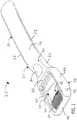
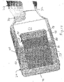
- a disposable, handheld device 20 for processing harvested dermal tissue includes a housing 21 presenting a substantially horizontally extending handle 22 and an interconnecting cutting head 24 extending forwardly from the handle.
- Handle 22 and cutting head 24 extend generally in the same plane, and are preferably formed from a plastic that is molded as an integral frame.
- device 20 can be formed from any suitable plastic, and is preferably injection or otherwise molded.
- Handle 22 defines an upper end 26, a lower end (not shown) opposite the upper end, and opposing sides 28. Handle 22 defines a necked-down gripping portion 30 at a location proximal the interface with cutting head 24. A pair of side cutouts 32 are formed in opposing sides 28, and a third cutout 34 is formed in the upper end 26. Cutouts 32 and 34 are substantially aligned, and ergonomically sized and shaped to be comfortably engaged by a user's thumb and other fingers.
- gripping portion 30 is symmetrical, device 20 can be equally engaged by a user's left or right hand in one of several ergonomic positions.
- cutting head 24 is defined at its periphery by a frame that includes a laterally extending rear wall 38 attached to handle 22, and side walls 40 extending forwardly from opposite ends of rear wall 38.
- a collection plate 42 can be disposed between side walls 40 to extend forwardly from rear wall 38 a distance less than the total length of side walls 40. It should be appreciated that plate 42 extends in a plane that is lower than the plane defined by the upper edges of rear and side walls 38 and 40. Accordingly, a receptacle 44 is optionally formed from plate 42 along with walls 38 and 40 that receives processed tissue, as will be described in more detail below.
- a laterally extending front wall 46 connects the outer ends of side walls 40.
- a void 50 is thus defined at the front of the cutting head 24 by front wall 46, side walls 40, and collection plate 42.
- a cutting assembly 60 is disposed within void 50 at a position upstream from collection plate 42 with respect to the direction of processed tissue particle travel during operation.
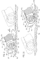
- Cutting assembly 60 is formed from a plurality of generally circular metal cutting blades 62 spaced apart by a plurality of washers 64 interposed between adjacent blades 62.
- Each blade 62 converges at its periphery to a circular blade tip 63.
- Tips 63 can be formed with a double bevel, single bevel, or serrated or jagged edge.
- Washers 64 have a diameter less than the diameter of cutting blades 62 such that blade tips 63 extend outwardly from adjacent washers 64.
- Cutting assembly 60 is rotatably supported by cutting head 24.
- a pair of aligned apertures 54 extends through the side walls 40 and receives a cylindrical axle 56.
- Axle 56 extends through the apertures 54, and receives a hub 58 extending centrally through cutting assembly 60.
- axle 56 is preferably rotatably fixed in apertures 54, and each blade 62 and washer 64 rotate independently around the axle 56.
- blades 62 and washers 64 can be interlocked or otherwise fastened to each other such that each cutting blade 62 is rotatably fixed to all other cutting blades of cutting assembly 60.
- the interlocked or fastened blades 62 and washers 64 can collectively rotate about axle 56, which is fixed within apertures 54.
- the interlocked or fastened blades 62 and 64 can be fixed with respect to rotation about axle 56, and axle can be inserted into apertures 54 via traditional roller bearings (not shown) that enable axle 56 to rotate with respect to cutting head 22.
- Washers 64 can assume any size, and preferably define a thickness between 100 microns and 5 mm. The distance between adjacent blade tips 63 is limited by the thickness of the corresponding blade 62 and washer 64, and is preferably within the range of 100 microns and 5 mm, and more preferably between 200 microns and 1200 microns.
- cutting assembly 60 has been described in accordance with the preferred embodiment, a skilled artisan will appreciate that washers 64 could be eliminated such that blades 62 are disposed immediately adjacent each other, and the blade tips are spaced apart a distance equal to the thickness of each blade 62. It should be further appreciated that cutting assembly 30 could be formed from a single elongated annular member having a plurality of spaced apart blade tips formed in its outer surface. The present invention is not intended to be limited to any of these embodiments.
- Cutting head 24 defines a wide V-shaped base 49 that includes the lower surface 51 of plate 42, and the lower surfaces 53 of side walls 40 at a location forward of plate.
- Lower surface 51 of plate 42 extends forward from rear wall 38, and slightly downwardly at an angle between 10 and 50 degrees with respect to the horizontal plane.
- Lower surface 53 is beveled at a location laterally aligned with void 50, and connect with lower surface 51.
- Lower surface 53 preferably defines an angle in the range of 10 and 50 degrees with respect to the horizontal plane, and preferably 30 degrees. Accordingly, device 20 can be tilted forwards to engage cutting assembly 60 with the harvested tissue that is to be processed.
- an upper and a lower tissue separator 66 and 68 are fastened to cutting head 24 and engage cutting assembly 60 to remove tissue that maybe disposed between adjacent blades 62 during cutting operations.
- Separators 66 and 68 are preferably formed from a metal, but could alternatively be formed from a plastic, ceramic, or other suitable material as appreciated by a skilled artisan.
- Upper separator 66 is a comb-like structure that defines a laterally extending base 70 and a plurality of tines 72 extending forwardly from base 70.
- Tines 72 define a thickness that is preferably slightly less than the thickness between adjacent blades 62.
- Base 70 is mounted to the upper surface of collection plate 42 at a location such that adjacent tines 72 extend forwardly and interdigitate with corresponding adjacent blade tips 63 in a one-to-one relationship, as illustrated in Fig. 3 .
- Tines 72 define distal ends 74 that ride along the outer surface of corresponding washers 64, preferably between the 12:00 and 2:00 position, and more preferably at approximately the 12:00 position.
- tines 72 are not to be construed as limited to the position of tines 72 with respect to washers 64. Furthermore, if cutting assembly 60 does not include washers 64, tines would extend between blade tips 63 to a location where sliced particles would tend to accumulate.
- a mounting flange 76 extends forwardly from lower surface 51 of plate 42, and slightly upwardly at an angle such that the lower surface of flange 76 extends along a plane that is tangential with respect to the outer periphery of washers 64.
- Flange 76 is preferably coplanar with lower surface 53.
- Lower separator 68 is a comb-like structure that defines a laterally extending base 78 and a plurality of tines 80 extending forwardly from base 78. Tines 80 define a thickness that is preferably slightly less than the thickness between adjacent blades 62.
- Base 78 is mounted to the lower surface of flange 76 such that adjacent tines 80 extend forwardly and interdigitate with corresponding adjacent blades 62 in a one-to-one relationship, as illustrated in Fig. 4 .
- Tines 80 define distal ends 81 that ride along the outer surface of corresponding washers 64, preferably at a position between 6:00 and 7:00. It should be appreciated that the present invention is not to be construed as limited to the position of tines 80 with respect to washers 64. Furthermore, if cutting assembly 60 does not include washers 64, tines 80 would extend between blade tips 63 to a location where sliced particles would tend to accumulate.
- either or both separators 66 and 68 can be actuated between a stand-by position, whereby tines 72 and 80 are removed from the interstices between adjacent blades 62, and an engaged position whereby tines 72 and 80 interdigitate with blades 62 as described above.
- bases 70 and 78 of separators 66 and 68 respectively, can be attached to cutting head 24 via a hinge (not shown), thus allowing the collection mechanism to be raised to the stand-by position, and lowered to the engaged position.
- a receptacle can be attached to the upper surface of cutting head 24.
- Receptacle 82 includes a pair of opposing side walls 84 joined at their outer ends by a rear end wall 86.
- a recessed collection plate 88 extends between side walls 84 and forwardly from end wall 86, and receives processed tissue during operation of device 20.
- Upper separator 66 is coupled to receptacle 82, and rides along guide rails (not shown) that are carried by side walls 84.
- the guide rails are angled such that separator 66 can be translated backwards and forward from the stand-by position illustrated in Fig. 13 to the engaged position illustrated in Fig. 14 .
- One or more detents can be formed in the guide rail and positioned to resist (though not prevent) translation of separator 66 away from both the stand-by and engaged positions. The detents enable a user to lock the separator 66 in the desired position during operation.
- lower separator 68 can alternatively be mounted onto a ramp 90 that is attached to lower surface 51 of plate 42.
- Ramp 90 presents a ramp surface 92 that is angled towards washers 64.
- Separator 68 slidably rides along ramp surface 92 via guide rails (not shown) or the like, and can thus be translated from the stand-by position illustrated in Fig. 15 to the engaged position illustrated in Fig. 16 .
- One or more detents can be formed in the guide rail and positioned to resist (though not prevent) translation of separator 68 away from both the stand-by and engaged positions. The detents enable a user to lock the separator 68 in the desired position during operation.
- device 20 lacks complex electrical components, it can be manufactured inexpensively compared to conventional dermal tissue processing devices.
- dermal tissue processing device 20 is capable of performing a forward and backward cutting operations.
- a sheet of harvested dermal tissue 94 is disposed on a cutting surface 96.
- Cutting surface 96 is preferably formed from a rubber, plastic, or other material suitable for supporting tissue 94 to be processed. It is desirable that surface 96 be sterile, sufficiently ductile and tacky to hold the tissue 94 in place and prevent slippage of the cutting blades 62, and durable to resist being cut by the blades during operation. Separators 66 and 68 (if movable) are then brought into engagement with cutting assembly 60.
- device 20 is tilted up and forward at an angle approximately equal to the angle of beveled surface 53 such that both surfaces 51 and 53 are clear from interference with the cutting surface. Tilting the device 20 provides the user with increased leverage to apply downward force when performing cutting operations.
- Device 20 is then lowered onto cutting surface 96 at a location immediately behind the tissue 94.
- the user applies a sufficient amount of downward force to enable cutting blades 62 to penetrate through tissue 94, and translates device 20 forward along the direction of Arrow A while maintaining engagement between blades 62 and cutting surface 96.
- the forward cutting operation thus ensues, whereby blades 62 thus rotate counterclockwise as indicated by Arrow B as they cut through the tissue 94.
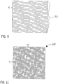
- the first forward cutting operation slices the tissue 94 into a plurality of adjacent fine strips 98 having a thickness T1 substantially equal to distance between adjacent cutting blade tips 63.
- sliced tissue 94 tends to become immediately lodged within the interstices between adjacent blades.
- the lodged strips 98 rotate along with blades 62 towards lower separator 68, and are brought into contact with the interdigitating tines 80.
- the tissue 94 rides along the lower cam surfaces of tines 80, becomes separated from cutting assembly 60, and falls back onto cutting surface 96 as substantially parallel strips 98.
- Lower separator 68 can be disengaged from cutting assembly 60 after the forward cutting operation, or blade can be rotated further counterclockwise, to force the distal ends of strips 98 onto the cutting surface 96. Multiple passes may be made if, for instance, the width of the harvested tissue 94 is greater than the distance between outer cutting blades 62.
- a backward cutting operation can be performed by orienting device 20 in a second direction, such as 90 degrees.
- a 90 degree orientation is preferred such that the cutting direction extends substantially orthogonal with respect to the strips 98.
- device 20 is positioned in front of strips 94, and lowered such that cutting assembly engages the front edge of the front-most strip.
- the user applies a sufficient amount of downward force to enable cutting blades 62 to penetrate through tissue 94.
- the backward cutting operation ensues, whereby device 20 is translated backwards along the direction of Arrow C while maintaining engagement between blades 62 and tissue 94. Blades 62 thus rotate clockwise as indicated by Arrow D.
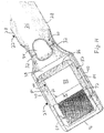
- the tissue 94 is sliced into fine particles 100 defined by two dimensions T1 and T2, each of which being as small as the distance between adjacent blade tips 63.
- Particles 100 in Fig. 11 are illustrated schematically in a grid-like pattern to identify dimensions T1 and T2 of substantially square or rectangular particles. The particles 100, of course, would separate and travel into receptacle 82 (if present) after the first backward cutting operation, and may not form a perfect grid on the cutting surface after two sequential forward cutting operations.
- sliced particles can assume any geometric configuration, regular or irregular, such as rectangles, triangles, and trapezoids.
- Dimensions T1 and T2 are therefore intended to be broadly construed to individually define the length of at least one of the edges of a particle of tissue sliced using device 20.
- Upper separator 68 can be disengaged from cutting assembly 60 after the backward cutting operation to force the remaining particles 100 onto collection plate 42 if the collection plate is present. Otherwise, if separator 68 is not movable, device 20 can be further translated along cutting surface 96 to ensure that all particles lodged in cutting assembly 60 engage the upper tines 72 and are removed. In rare instances, a tool can be inserted into the interstices between blades 62 and used to force the remaining particles 100 onto collection plate 42. Multiple backwards passes can be made if, for instance, strips 98 are longer than the distance between outer cutting blades 62.
- particles 100 can define dimensions T1 and T2 within the range of 100 microns and 5 mm, and preferably between 200 and 1200 microns depending on the distance between adjacent blade tips 63.
- the user may wish to perform more than one forward and backward cutting operation.
- additional cutting operations in either direction can be performed as desired.
- a backward cutting operation can then be performed to accumulate the further sliced particles in receptacle 82, if present. If, upon examination of the accumulated particles, the desired edge dimensions have not yet been achieved, the particles can be poured out of receptacle 82 onto cutting surface 96, and one or more additional cutting operations can be performed.
- particles having dimensions T1 and T2 between 100 and 1200 microns can be prepared using device 20.
- Transplanted particles as small as 100 to 1200 microns have been found to achieve better results than larger particles, as they enable increased expansion ratios.
- the processed tissue can be transplanted into a wound.
- the present invention provides a dermal tissue processing device 20 that is portable, manually operated, and relatively inexpensive, thereby rendering the device 20 disposable after one use.
- the labor required to clean and sterilize conventional dermal tissue processors is thus avoided.
- the present device 20 can be positioned by the user in any desirable orientation relative to the tissue without having to adjust the position of the tissue.
- Device 20 thereby provides the user with enhanced cutting operation flexibility with respect to conventional devices.
- device 20 enables the operator to easily remove finely sliced particles from between adjacent blades 62.
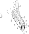
- the present invention provides a pivotable second handle 102 that can be connected to cutting head 24.
- Handle 102 presents a second surface that can be engaged by the user to provide greater leverage when applying downward pressure during cutting operations.
- Second handle 102 for instance, can define a gripping surface 104 connected to cutting head 24 via a pair of interconnecting legs 106.
- Each leg 106 can define an aperture 108 extending therethrough and aligned with apertures 54, such that axle 56 extends through both pairs of apertures 54 and 108.
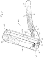
- Second handle 102 can thus be pivoted from a flat storage position as illustrated in Fig. 17 , whereby gripping surface 104 rests against handle 22, to an engaged position as illustrated in Fig. 18 , whereby handle 102 extends substantially vertical.
- a flange 110 extends outwardly from front wall 46 and engages the forward surface of legs 106 when handle 102 is engaged to prevent over-rotation of the handle.
- flange 110 can be configured to allow handle 102 to pivot to a position between the vertical position illustrated and a horizontal position on the opposite side of cutting head 24 with respect handle 22 to assist during forward cutting operations.
- a second flange (not shown) can be provided that is selectively engaged and allows handle 102 to pivot to a position between the vertical and closed positions illustrated to assist during backward cutting operations.
- the user can grip handle 22 with his or her dominant hand to guide the cutting direction, and engage second handle 102 with the other hand to apply additional downward force during the cutting operation.
Landscapes
- Health & Medical Sciences (AREA)
- Surgery (AREA)
- Life Sciences & Earth Sciences (AREA)
- Heart & Thoracic Surgery (AREA)
- Molecular Biology (AREA)
- Transplantation (AREA)
- Engineering & Computer Science (AREA)
- Biomedical Technology (AREA)
- Plastic & Reconstructive Surgery (AREA)
- Medical Informatics (AREA)
- Nuclear Medicine, Radiotherapy & Molecular Imaging (AREA)
- Animal Behavior & Ethology (AREA)
- General Health & Medical Sciences (AREA)
- Public Health (AREA)
- Veterinary Medicine (AREA)
- Surgical Instruments (AREA)
- Prostheses (AREA)
Applications Claiming Priority (3)
| Application Number | Priority Date | Filing Date | Title |
|---|---|---|---|
| US45037503P | 2003-02-27 | 2003-02-27 | |
| US450375P | 2003-02-27 | ||
| PCT/US2004/006248 WO2004075764A1 (en) | 2003-02-27 | 2004-02-27 | Method and apparatus for processing dermal tissue |
Publications (2)
| Publication Number | Publication Date |
|---|---|
| EP1596734A1 EP1596734A1 (en) | 2005-11-23 |
| EP1596734B1 true EP1596734B1 (en) | 2018-04-11 |
Family
ID=32927645
Family Applications (1)
| Application Number | Title | Priority Date | Filing Date |
|---|---|---|---|
| EP04715801.9A Expired - Lifetime EP1596734B1 (en) | 2003-02-27 | 2004-02-27 | Method and apparatus for processing dermal tissue |
Country Status (8)
| Country | Link |
|---|---|
| US (2) | US7625384B2 (enExample) |
| EP (1) | EP1596734B1 (enExample) |
| JP (1) | JP4538584B2 (enExample) |
| CN (1) | CN100515354C (enExample) |
| AU (1) | AU2004215916B2 (enExample) |
| CA (1) | CA2516554C (enExample) |
| ES (1) | ES2676994T3 (enExample) |
| WO (1) | WO2004075764A1 (enExample) |
Families Citing this family (114)
| Publication number | Priority date | Publication date | Assignee | Title |
|---|---|---|---|---|
| US7666192B2 (en) * | 2001-02-16 | 2010-02-23 | Kci Licensing, Inc. | Skin grafting devices and methods |
| US7651507B2 (en) * | 2003-03-03 | 2010-01-26 | Kci Licensing, Inc. | Tissue processing system |
| US8501396B2 (en) | 2001-11-05 | 2013-08-06 | Medgenics Medical Israel Ltd. | Dermal micro-organs, methods and apparatuses for producing and using the same |
| US8088568B2 (en) | 2001-11-05 | 2012-01-03 | Medgentics, Inc. | Dermal micro-organs, methods and apparatuses for producing and using the same |
| US7468242B2 (en) | 2001-11-05 | 2008-12-23 | Medgenics, Inc. | Dermal micro organs, methods and apparatuses for producing and using the same |
| US7708746B2 (en) * | 2003-02-27 | 2010-05-04 | Wright Medical Technology, Inc. | Method and apparatus for processing dermal tissue |
| ES2676994T3 (es) | 2003-02-27 | 2018-07-27 | Applied Tissue Technologies Llc | Método y aparato para tratar tejido dérmico |
| US20040175690A1 (en) | 2003-03-03 | 2004-09-09 | Kci Licensing, Inc. | Tissue harvesting device and method |
| EP2377404A1 (en) | 2003-05-01 | 2011-10-19 | Medgenics, Inc. | A dermal micro-organ which is an explant of living tissue |
| CN101090673A (zh) * | 2004-12-21 | 2007-12-19 | 克里斯托弗·格雷斯 | 用于去除不雅观皮肤的装置 |
| TWI270362B (en) * | 2004-12-28 | 2007-01-11 | Ind Tech Res Inst | Cell subcloning device |
| US7547314B2 (en) * | 2006-05-26 | 2009-06-16 | Terumo Cardiovascular Systems Corporation | Self-cleaning endoscopic vein harvester rod |
| US8308701B2 (en) | 2010-11-15 | 2012-11-13 | Aquesys, Inc. | Methods for deploying intraocular shunts |
| US8852256B2 (en) | 2010-11-15 | 2014-10-07 | Aquesys, Inc. | Methods for intraocular shunt placement |
| US8801766B2 (en) | 2010-11-15 | 2014-08-12 | Aquesys, Inc. | Devices for deploying intraocular shunts |
| US8721702B2 (en) | 2010-11-15 | 2014-05-13 | Aquesys, Inc. | Intraocular shunt deployment devices |
| US8758290B2 (en) | 2010-11-15 | 2014-06-24 | Aquesys, Inc. | Devices and methods for implanting a shunt in the suprachoroidal space |
| US20120123316A1 (en) | 2010-11-15 | 2012-05-17 | Aquesys, Inc. | Intraocular shunts for placement in the intra-tenon's space |
| US10085884B2 (en) | 2006-06-30 | 2018-10-02 | Aquesys, Inc. | Intraocular devices |
| JP5396272B2 (ja) * | 2006-06-30 | 2014-01-22 | アクエシス インコーポレイテッド | 臓器内圧力軽減のための方法、システムおよび装置 |
| US8663303B2 (en) | 2010-11-15 | 2014-03-04 | Aquesys, Inc. | Methods for deploying an intraocular shunt from a deployment device and into an eye |
| US8974511B2 (en) | 2010-11-15 | 2015-03-10 | Aquesys, Inc. | Methods for treating closed angle glaucoma |
| US8852137B2 (en) | 2010-11-15 | 2014-10-07 | Aquesys, Inc. | Methods for implanting a soft gel shunt in the suprachoroidal space |
| US8828070B2 (en) | 2010-11-15 | 2014-09-09 | Aquesys, Inc. | Devices for deploying intraocular shunts |
| US9095411B2 (en) * | 2010-11-15 | 2015-08-04 | Aquesys, Inc. | Devices for deploying intraocular shunts |
| US8454948B2 (en) | 2006-09-14 | 2013-06-04 | Medgenics Medical Israel Ltd. | Long lasting drug formulations |
| CN101610793B (zh) | 2006-09-14 | 2012-10-24 | 迈德詹尼克斯医疗以色列有限公司 | 长效药物制剂 |
| US9127084B2 (en) | 2006-09-14 | 2015-09-08 | Medgenics Medical Israel Ltd. | Long lasting drug formulations |
| HUP0700524A2 (en) | 2007-08-10 | 2010-01-28 | Pecsi Tudomanyegyetem | Cartilage allograft for replacement of cartilage damages, and process and accessories for producing thereof |
| US9687276B2 (en) | 2007-09-14 | 2017-06-27 | International Edge Inc. | Skin removing implement |
| USD596802S1 (en) | 2007-09-14 | 2009-07-21 | International Edge Inc. | Foot micro file |
| USD596353S1 (en) | 2007-09-14 | 2009-07-14 | International Edge Inc. | Combined foot micro file and holder |
| US8814881B2 (en) * | 2007-12-13 | 2014-08-26 | Zimmer Surgical, Inc. | Dermatome with orientation guides |
| US8002779B2 (en) * | 2007-12-13 | 2011-08-23 | Zimmer Surgical, Inc. | Dermatome blade assembly |
| USD604848S1 (en) | 2008-06-03 | 2009-11-24 | International Edge, Inc. | Foot file with handle |
| CA2678985A1 (en) * | 2008-09-22 | 2010-03-22 | Mcneil-Ppc, Inc. | Absorbent article including fragrance emitting layer |
| US20110077664A1 (en) * | 2009-09-28 | 2011-03-31 | Wright Medical Technology, Inc. | Device for processing dermal tissue |
| US8900181B2 (en) * | 2009-12-18 | 2014-12-02 | Srgi Holdings, Llc | Skin treatment and drug delivery device |
| JP5833832B2 (ja) | 2010-06-30 | 2015-12-16 | テルモ株式会社 | 生体移植片移送器具及び生体移植片の移送方法 |
| US9597111B2 (en) | 2010-08-06 | 2017-03-21 | Kci Licensing, Inc. | Methods for applying a skin graft |
| US8562626B2 (en) | 2010-08-06 | 2013-10-22 | MoMelan Technologies, Inc. | Devices for harvesting a skin graft |
| US8617181B2 (en) | 2010-08-06 | 2013-12-31 | MoMelan Technologies, Inc. | Methods for preparing a skin graft |
| US8926631B2 (en) | 2010-08-06 | 2015-01-06 | MoMelan Technologies, Inc. | Methods for preparing a skin graft without culturing or use of biologics |
| US9610093B2 (en) | 2010-08-06 | 2017-04-04 | Kci Licensing, Inc. | Microblister skin grafting |
| US8978234B2 (en) | 2011-12-07 | 2015-03-17 | MoMelan Technologies, Inc. | Methods of manufacturing devices for generating skin grafts |
| US9173674B2 (en) | 2010-08-06 | 2015-11-03 | MoMelan Technologies, Inc. | Devices for harvesting a skin graft |
| US8585629B2 (en) | 2010-11-15 | 2013-11-19 | Aquesys, Inc. | Systems for deploying intraocular shunts |
| US20160256319A1 (en) | 2010-11-15 | 2016-09-08 | Aquesys, Inc. | Intraocular shunt placement in the suprachoroidal space |
| US11000310B2 (en) | 2010-12-17 | 2021-05-11 | Srgi Holdings, Llc | Pixel array medical systems, devices and methods |
| US11278309B2 (en) | 2010-12-17 | 2022-03-22 | Srgi Holdings, Llc | Pixel array medical systems, devices and methods |
| US11109887B2 (en) | 2013-12-06 | 2021-09-07 | Srgi Holdings, Llc | Pixel array medical systems, devices and methods |
| US10905865B2 (en) | 2010-12-17 | 2021-02-02 | Srgi Holdings, Llc | Systems, devices and methods for fractional resection, fractional skin grafting, fractional scar reduction and fractional tattoo removal |
| US10736653B2 (en) | 2013-12-06 | 2020-08-11 | Srgi Holdings, Llc | Pixel array medical systems, devices and methods |
| US10342574B2 (en) | 2010-12-17 | 2019-07-09 | Srgi Holdings, Llc | Pixel array medical devices and methods |
| US10695546B2 (en) | 2010-12-17 | 2020-06-30 | Srgi Holdings, Llc | Systems, devices and methods for fractional resection, fractional skin grafting, fractional scar reduction and fractional tattoo removal |
| US11103275B2 (en) | 2010-12-17 | 2021-08-31 | Srgi Holdings, Llc | Pixel array medical systems, devices and methods |
| US10702684B2 (en) | 2010-12-17 | 2020-07-07 | Srgi Holdings, Llc | Systems, devices and methods for fractional resection, fractional skin grafting, fractional scar reduction and fractional tattoo removal |
| US10772658B2 (en) | 2010-12-17 | 2020-09-15 | Srgi Holdings, Llc | Pixel array medical systems, devices and methods |
| US20120197267A1 (en) | 2011-01-27 | 2012-08-02 | MoMelan Technologies, Inc. | Devices for generating and transferring micrografts and methods of use thereof |
| WO2012145504A1 (en) | 2011-04-20 | 2012-10-26 | Kci Licensing, Inc. | Skin graft devices and methods |
| CN102283718A (zh) * | 2011-07-12 | 2011-12-21 | 中国农业大学 | 一种分离腔前卵泡的方法及其专用刀 |
| US9808373B2 (en) | 2013-06-28 | 2017-11-07 | Aquesys, Inc. | Intraocular shunt implantation |
| US10080682B2 (en) | 2011-12-08 | 2018-09-25 | Aquesys, Inc. | Intrascleral shunt placement |
| US9610195B2 (en) | 2013-02-27 | 2017-04-04 | Aquesys, Inc. | Intraocular shunt implantation methods and devices |
| US8765210B2 (en) | 2011-12-08 | 2014-07-01 | Aquesys, Inc. | Systems and methods for making gelatin shunts |
| US8852136B2 (en) | 2011-12-08 | 2014-10-07 | Aquesys, Inc. | Methods for placing a shunt into the intra-scleral space |
| USD729386S1 (en) * | 2012-07-13 | 2015-05-12 | MoMelan Technologies, Inc. | Dermatological system |
| USD706422S1 (en) * | 2012-07-13 | 2014-06-03 | Momelan Technologies | Dermatological device |
| US9055970B2 (en) | 2012-10-12 | 2015-06-16 | Zimmer Surgical, Inc. | Skin graft preparation device |
| WO2014089488A2 (en) * | 2012-12-06 | 2014-06-12 | Srgi Holdings Llc | Pixel array medical devices and methods |
| US9125723B2 (en) | 2013-02-19 | 2015-09-08 | Aquesys, Inc. | Adjustable glaucoma implant |
| US10159600B2 (en) | 2013-02-19 | 2018-12-25 | Aquesys, Inc. | Adjustable intraocular flow regulation |
| AU2014239952B2 (en) | 2013-03-14 | 2018-09-27 | Solventum Intellectual Properties Company | Absorbent substrates for harvesting skin grafts |
| ES2827049T3 (es) | 2013-10-02 | 2021-05-19 | Srgi Holdings Llc | Dispositivos médicos de conjunto de píxeles |
| SG11201602636PA (en) | 2013-10-02 | 2016-05-30 | Srgi Holdings Llc | Pixel array medical devices and methods |
| CN108403215B (zh) | 2013-11-14 | 2021-03-23 | 阿奎西斯公司 | 眼内分流器插入器 |
| US11937846B2 (en) | 2013-12-06 | 2024-03-26 | Srgi Holdings Llc | Pixel array medical systems, devices and methods |
| US11229452B2 (en) | 2013-12-06 | 2022-01-25 | Srgi Holdings, Llc | Pixel array medical systems, devices and methods |
| EP3626188B1 (en) | 2013-12-31 | 2021-08-18 | 3M Innovative Properties Company | Sensor systems for skin graft harvesting |
| US10463392B2 (en) | 2013-12-31 | 2019-11-05 | Kci Licensing, Inc. | Fluid-assisted skin graft harvesting |
| JP6214409B2 (ja) * | 2014-01-27 | 2017-10-18 | 大日本印刷株式会社 | 組織切除用受け台 |
| US20150297095A1 (en) * | 2014-04-21 | 2015-10-22 | Fried Robert | Reversible thermochromatic liquid crystal contact means for self-detection of subdermal abnormal cell metabolism |
| EP3253308A4 (en) | 2015-02-05 | 2018-10-24 | SRGI Holdings LLC | Pixel array medical systems, devices and methods |
| EP3280465B1 (en) | 2015-04-09 | 2020-12-16 | 3M Innovative Properties Company | Soft-tack, porous substrates for harvesting skin grafts |
| KR102268628B1 (ko) | 2015-06-03 | 2021-06-24 | 아큐시스, 인코포레이티드 | 안구내 션트의 외부 배치 |
| US20160374704A1 (en) * | 2015-06-29 | 2016-12-29 | Applied Tissue Technologies Llc | Systems and methods for distributing skin particles |
| US11980389B2 (en) | 2015-08-31 | 2024-05-14 | Srgi Holdings Llc | Handed spiral slotted scalpet array |
| US11490952B2 (en) | 2015-08-31 | 2022-11-08 | Srgi Holdings, Llc | Pixel array medical devices and methods |
| US11751904B2 (en) | 2015-08-31 | 2023-09-12 | Srgi Holdings, Llc | Pixel array medical systems, devices and methods |
| US11006974B2 (en) | 2015-11-03 | 2021-05-18 | Kci Licensing, Inc. | Devices for creating an epidermal graft sheet |
| USD796671S1 (en) * | 2016-01-21 | 2017-09-05 | Roger Khouri | Tissue mesher |
| SE541418C2 (en) | 2016-01-22 | 2019-09-24 | S2Medical Ab | Minimally invasive tissue harvesting device |
| US11564706B2 (en) | 2019-10-28 | 2023-01-31 | Srgi Holdings, Llc | Pixel array medical systems, devices and methods |
| US10537349B1 (en) * | 2016-02-08 | 2020-01-21 | Lifecell Corporation | Method for processing tissue to control thickness |
| KR102448313B1 (ko) * | 2016-05-03 | 2022-09-28 | 에스알쥐아이 홀딩스 엘엘씨 | 픽셀 어레이 의료 시스템, 장치 및 방법 |
| EP3463228A4 (en) | 2016-06-02 | 2020-03-04 | Aquesys, Inc. | INTRAOCULAR ADMINISTRATION OF MEDICINES |
| US11185346B1 (en) * | 2017-01-10 | 2021-11-30 | Musculoskeletal Transplant Foundation | Multi-blade cutting device |
| CN107361797A (zh) * | 2017-08-11 | 2017-11-21 | 浙江省皮肤病防治研究所 | 一种麻风病患者组织液采集器械 |
| USD886384S1 (en) | 2017-09-22 | 2020-06-02 | Davinci Ii Csj, Llc | Abrasive skin treatment device |
| USD872370S1 (en) | 2017-09-22 | 2020-01-07 | Davinci Ii Csj, Llc | Abrasive skin treatment device |
| US11246753B2 (en) | 2017-11-08 | 2022-02-15 | Aquesys, Inc. | Manually adjustable intraocular flow regulation |
| CN108523968B (zh) * | 2018-02-26 | 2020-07-24 | 河北北方学院附属第一医院 | 一种皮肤科用病灶刮清器 |
| US11135089B2 (en) | 2018-03-09 | 2021-10-05 | Aquesys, Inc. | Intraocular shunt inserter |
| US10952898B2 (en) | 2018-03-09 | 2021-03-23 | Aquesys, Inc. | Intraocular shunt inserter |
| US11589895B1 (en) | 2019-08-19 | 2023-02-28 | Musculoskeletal Transplant Foundation | Tissue separation device and methods for using same |
| US20230181209A1 (en) * | 2020-03-06 | 2023-06-15 | The Johns Hopkins University | Mechanism for dicing cartilage |
| CN112120760B (zh) * | 2020-09-24 | 2022-01-18 | 青岛市城阳区人民医院 | 一种适用于烧伤科的辊轴取皮刀具 |
| CN112641492A (zh) * | 2020-12-21 | 2021-04-13 | 郑广泉 | 快速制备微粒皮的新型手术刀具 |
| USD1005504S1 (en) | 2020-12-23 | 2023-11-21 | Telebrands Corp. | Abrasive skin treatment device |
| USD1017136S1 (en) | 2020-12-23 | 2024-03-05 | Telebrands Corp. | Abrasive skin treatment device |
| USD1022327S1 (en) | 2020-12-23 | 2024-04-09 | International Edge, Inc. | Foot file |
| CN113017783B (zh) * | 2021-03-02 | 2022-02-11 | 中国人民解放军总医院第四医学中心 | 一种锥体皮取皮器 |
| USD1023468S1 (en) | 2021-03-29 | 2024-04-16 | Telebrands Corp. | Foot file |
| CN113545828B (zh) * | 2021-08-16 | 2024-08-16 | 上海交通大学医学院附属瑞金医院 | 一种轧皮装置 |
Family Cites Families (18)
| Publication number | Priority date | Publication date | Assignee | Title |
|---|---|---|---|---|
| FR1009467A (fr) | 1950-01-27 | 1952-05-29 | Appareil permettant les prélèvements de greffons cutanés | |
| US2839109A (en) | 1956-08-17 | 1958-06-17 | Jack K Wilson | Woodworking plane |
| US3076462A (en) | 1958-09-15 | 1963-02-05 | Jr S P Wall | Microdermatome |
| FR1497723A (fr) * | 1966-10-14 | 1967-10-13 | Drapier Sa | Perforateur à rouleaux |
| US3640279A (en) | 1967-12-07 | 1972-02-08 | Warren F Brown | Skin graft cutting method and machine |
| US4136746A (en) * | 1977-05-23 | 1979-01-30 | Tusing Arthur P | Bearing assembly for farm implements incorporating rotatable discs |
| IL68193A (en) * | 1983-03-22 | 1986-11-30 | Rosenberg Lior | Dermatome for cutting skin |
| US5219352A (en) * | 1989-07-03 | 1993-06-15 | Zimmer, Inc. | Skin graft preparation apparatus |
| US5004468A (en) | 1989-07-03 | 1991-04-02 | Zimmer | Skin graft preparation apparatus |
| US5196020A (en) * | 1991-09-30 | 1993-03-23 | Zimmer, Inc. | Comb for use with skin graft preparation apparatus |
| CA2149836C (en) * | 1994-05-23 | 1999-07-06 | Sang Bae Choi | Perforating device for dermal administration |
| IL116282A (en) * | 1995-12-07 | 2000-10-31 | L R Surgical Instr Ltd | Adjustable mesher device and a system for using the same |
| NL1004276C2 (nl) | 1996-10-15 | 1998-04-20 | Willem Marie Ysebaert | Werkwijzen voor het vervaardigen van huideilandjes, voor het verplaatsen van huid of huideilandjes, voor het spreiden van huideilandjes en het aanbrengen hiervan op een brandwond, alsmede een houder, snijraam, snijtafel, contradrager, klemorgaan, membraan, transportorgaan en spreidingsorgaan om te worden toegepast voor dergelijke werkwijzen. |
| CA2220755A1 (en) * | 1997-11-10 | 1999-05-10 | Michael S.G. Bell | Skin graft preparation tool |
| DE19958855C2 (de) | 1999-12-07 | 2003-07-03 | Klaus Kasten | Handgerät zur Präparation eines Vollhaut-Transplantats durch Abtragen von Hautgewebeschichten |
| MXPA04004387A (es) | 2001-11-05 | 2005-07-05 | Medgenics Inc | Metodo y aparato para la produccion de in injerto de piel y el injerto producido por los mismos. |
| ES2676994T3 (es) | 2003-02-27 | 2018-07-27 | Applied Tissue Technologies Llc | Método y aparato para tratar tejido dérmico |
| US20040175690A1 (en) * | 2003-03-03 | 2004-09-09 | Kci Licensing, Inc. | Tissue harvesting device and method |
-
2004
- 2004-02-27 ES ES04715801.9T patent/ES2676994T3/es not_active Expired - Lifetime
- 2004-02-27 WO PCT/US2004/006248 patent/WO2004075764A1/en not_active Ceased
- 2004-02-27 JP JP2006503925A patent/JP4538584B2/ja not_active Expired - Lifetime
- 2004-02-27 CA CA2516554A patent/CA2516554C/en not_active Expired - Lifetime
- 2004-02-27 EP EP04715801.9A patent/EP1596734B1/en not_active Expired - Lifetime
- 2004-02-27 US US10/789,620 patent/US7625384B2/en not_active Expired - Lifetime
- 2004-02-27 AU AU2004215916A patent/AU2004215916B2/en not_active Expired
- 2004-02-27 CN CNB2004800054203A patent/CN100515354C/zh not_active Expired - Lifetime
-
2009
- 2009-10-21 US US12/603,190 patent/US8187285B2/en not_active Expired - Lifetime
Also Published As
| Publication number | Publication date |
|---|---|
| WO2004075764A1 (en) | 2004-09-10 |
| ES2676994T3 (es) | 2018-07-27 |
| US7625384B2 (en) | 2009-12-01 |
| US20040230215A1 (en) | 2004-11-18 |
| US20100042127A1 (en) | 2010-02-18 |
| CN100515354C (zh) | 2009-07-22 |
| EP1596734A1 (en) | 2005-11-23 |
| CA2516554C (en) | 2012-09-25 |
| JP2006519071A (ja) | 2006-08-24 |
| CA2516554A1 (en) | 2004-09-10 |
| US8187285B2 (en) | 2012-05-29 |
| JP4538584B2 (ja) | 2010-09-08 |
| AU2004215916A1 (en) | 2004-09-10 |
| WO2004075764B1 (en) | 2005-02-17 |
| CN1753648A (zh) | 2006-03-29 |
| AU2004215916B2 (en) | 2010-07-29 |
Similar Documents
| Publication | Publication Date | Title |
|---|---|---|
| EP1596734B1 (en) | Method and apparatus for processing dermal tissue | |
| US7708746B2 (en) | Method and apparatus for processing dermal tissue | |
| US8162957B2 (en) | Tissue processing system | |
| US7926401B2 (en) | Tissue harvesting device and method | |
| CN1262402C (zh) | 用于切割水果和蔬菜尤其是洋葱的切割装置 | |
| US20050101972A1 (en) | Devices and systems for separating and preparing skin | |
| JP2007534507A (ja) | 果実および野菜、特にタマネギを切断するための装置 | |
| WO2010021466A1 (ko) | 식재료 절단용 가위 | |
| CN119098996A (zh) | 辅助莫氏手术的切片器 | |
| CN117503283A (zh) | 一种颈椎后纵韧带剥离切开器 | |
| HK1077992B (en) | Tissue processing system |
Legal Events
| Date | Code | Title | Description |
|---|---|---|---|
| PUAI | Public reference made under article 153(3) epc to a published international application that has entered the european phase |
Free format text: ORIGINAL CODE: 0009012 |
|
| 17P | Request for examination filed |
Effective date: 20050912 |
|
| AK | Designated contracting states |
Kind code of ref document: A1 Designated state(s): AT BE BG CH CY CZ DE DK EE ES FI FR GB GR HU IE IT LI LU MC NL PT RO SE SI SK TR |
|
| AX | Request for extension of the european patent |
Extension state: AL LT LV MK |
|
| DAX | Request for extension of the european patent (deleted) | ||
| 17Q | First examination report despatched |
Effective date: 20101026 |
|
| RAP1 | Party data changed (applicant data changed or rights of an application transferred) |
Owner name: APPLIED TISSUE TECHNOLOGIES LLC |
|
| GRAP | Despatch of communication of intention to grant a patent |
Free format text: ORIGINAL CODE: EPIDOSNIGR1 |
|
| STAA | Information on the status of an ep patent application or granted ep patent |
Free format text: STATUS: GRANT OF PATENT IS INTENDED |
|
| INTG | Intention to grant announced |
Effective date: 20171017 |
|
| RAP1 | Party data changed (applicant data changed or rights of an application transferred) |
Owner name: APPLIED TISSUE TECHNOLOGIES LLC |
|
| RIN1 | Information on inventor provided before grant (corrected) |
Inventor name: BAKER, CHRISTIAN Inventor name: ERIKSSON, ELOF Inventor name: ALLISON, ROBERT, W. |
|
| GRAS | Grant fee paid |
Free format text: ORIGINAL CODE: EPIDOSNIGR3 |
|
| GRAA | (expected) grant |
Free format text: ORIGINAL CODE: 0009210 |
|
| STAA | Information on the status of an ep patent application or granted ep patent |
Free format text: STATUS: THE PATENT HAS BEEN GRANTED |
|
| AK | Designated contracting states |
Kind code of ref document: B1 Designated state(s): AT BE BG CH CY CZ DE DK EE ES FI FR GB GR HU IE IT LI LU MC NL PT RO SE SI SK TR |
|
| REG | Reference to a national code |
Ref country code: GB Ref legal event code: FG4D |
|
| REG | Reference to a national code |
Ref country code: CH Ref legal event code: EP |
|
| REG | Reference to a national code |
Ref country code: AT Ref legal event code: REF Ref document number: 987147 Country of ref document: AT Kind code of ref document: T Effective date: 20180415 |
|
| REG | Reference to a national code |
Ref country code: IE Ref legal event code: FG4D |
|
| REG | Reference to a national code |
Ref country code: DE Ref legal event code: R096 Ref document number: 602004052580 Country of ref document: DE |
|
| REG | Reference to a national code |
Ref country code: ES Ref legal event code: FG2A Ref document number: 2676994 Country of ref document: ES Kind code of ref document: T3 Effective date: 20180727 |
|
| REG | Reference to a national code |
Ref country code: NL Ref legal event code: MP Effective date: 20180411 |
|
| PG25 | Lapsed in a contracting state [announced via postgrant information from national office to epo] |
Ref country code: NL Free format text: LAPSE BECAUSE OF FAILURE TO SUBMIT A TRANSLATION OF THE DESCRIPTION OR TO PAY THE FEE WITHIN THE PRESCRIBED TIME-LIMIT Effective date: 20180411 |
|
| PG25 | Lapsed in a contracting state [announced via postgrant information from national office to epo] |
Ref country code: BG Free format text: LAPSE BECAUSE OF FAILURE TO SUBMIT A TRANSLATION OF THE DESCRIPTION OR TO PAY THE FEE WITHIN THE PRESCRIBED TIME-LIMIT Effective date: 20180711 Ref country code: FI Free format text: LAPSE BECAUSE OF FAILURE TO SUBMIT A TRANSLATION OF THE DESCRIPTION OR TO PAY THE FEE WITHIN THE PRESCRIBED TIME-LIMIT Effective date: 20180411 Ref country code: SE Free format text: LAPSE BECAUSE OF FAILURE TO SUBMIT A TRANSLATION OF THE DESCRIPTION OR TO PAY THE FEE WITHIN THE PRESCRIBED TIME-LIMIT Effective date: 20180411 |
|
| PG25 | Lapsed in a contracting state [announced via postgrant information from national office to epo] |
Ref country code: GR Free format text: LAPSE BECAUSE OF FAILURE TO SUBMIT A TRANSLATION OF THE DESCRIPTION OR TO PAY THE FEE WITHIN THE PRESCRIBED TIME-LIMIT Effective date: 20180712 |
|
| REG | Reference to a national code |
Ref country code: AT Ref legal event code: MK05 Ref document number: 987147 Country of ref document: AT Kind code of ref document: T Effective date: 20180411 |
|
| PG25 | Lapsed in a contracting state [announced via postgrant information from national office to epo] |
Ref country code: PT Free format text: LAPSE BECAUSE OF FAILURE TO SUBMIT A TRANSLATION OF THE DESCRIPTION OR TO PAY THE FEE WITHIN THE PRESCRIBED TIME-LIMIT Effective date: 20180813 |
|
| REG | Reference to a national code |
Ref country code: DE Ref legal event code: R097 Ref document number: 602004052580 Country of ref document: DE |
|
| PG25 | Lapsed in a contracting state [announced via postgrant information from national office to epo] |
Ref country code: SK Free format text: LAPSE BECAUSE OF FAILURE TO SUBMIT A TRANSLATION OF THE DESCRIPTION OR TO PAY THE FEE WITHIN THE PRESCRIBED TIME-LIMIT Effective date: 20180411 Ref country code: RO Free format text: LAPSE BECAUSE OF FAILURE TO SUBMIT A TRANSLATION OF THE DESCRIPTION OR TO PAY THE FEE WITHIN THE PRESCRIBED TIME-LIMIT Effective date: 20180411 Ref country code: CZ Free format text: LAPSE BECAUSE OF FAILURE TO SUBMIT A TRANSLATION OF THE DESCRIPTION OR TO PAY THE FEE WITHIN THE PRESCRIBED TIME-LIMIT Effective date: 20180411 Ref country code: DK Free format text: LAPSE BECAUSE OF FAILURE TO SUBMIT A TRANSLATION OF THE DESCRIPTION OR TO PAY THE FEE WITHIN THE PRESCRIBED TIME-LIMIT Effective date: 20180411 Ref country code: AT Free format text: LAPSE BECAUSE OF FAILURE TO SUBMIT A TRANSLATION OF THE DESCRIPTION OR TO PAY THE FEE WITHIN THE PRESCRIBED TIME-LIMIT Effective date: 20180411 Ref country code: EE Free format text: LAPSE BECAUSE OF FAILURE TO SUBMIT A TRANSLATION OF THE DESCRIPTION OR TO PAY THE FEE WITHIN THE PRESCRIBED TIME-LIMIT Effective date: 20180411 |
|
| PLBE | No opposition filed within time limit |
Free format text: ORIGINAL CODE: 0009261 |
|
| STAA | Information on the status of an ep patent application or granted ep patent |
Free format text: STATUS: NO OPPOSITION FILED WITHIN TIME LIMIT |
|
| 26N | No opposition filed |
Effective date: 20190114 |
|
| PG25 | Lapsed in a contracting state [announced via postgrant information from national office to epo] |
Ref country code: SI Free format text: LAPSE BECAUSE OF FAILURE TO SUBMIT A TRANSLATION OF THE DESCRIPTION OR TO PAY THE FEE WITHIN THE PRESCRIBED TIME-LIMIT Effective date: 20180411 |
|
| REG | Reference to a national code |
Ref country code: CH Ref legal event code: PL |
|
| PG25 | Lapsed in a contracting state [announced via postgrant information from national office to epo] |
Ref country code: LU Free format text: LAPSE BECAUSE OF NON-PAYMENT OF DUE FEES Effective date: 20190227 Ref country code: MC Free format text: LAPSE BECAUSE OF FAILURE TO SUBMIT A TRANSLATION OF THE DESCRIPTION OR TO PAY THE FEE WITHIN THE PRESCRIBED TIME-LIMIT Effective date: 20180411 |
|
| REG | Reference to a national code |
Ref country code: BE Ref legal event code: MM Effective date: 20190228 |
|
| REG | Reference to a national code |
Ref country code: IE Ref legal event code: MM4A |
|
| PG25 | Lapsed in a contracting state [announced via postgrant information from national office to epo] |
Ref country code: CH Free format text: LAPSE BECAUSE OF NON-PAYMENT OF DUE FEES Effective date: 20190228 Ref country code: LI Free format text: LAPSE BECAUSE OF NON-PAYMENT OF DUE FEES Effective date: 20190228 |
|
| PG25 | Lapsed in a contracting state [announced via postgrant information from national office to epo] |
Ref country code: IE Free format text: LAPSE BECAUSE OF NON-PAYMENT OF DUE FEES Effective date: 20190227 |
|
| PG25 | Lapsed in a contracting state [announced via postgrant information from national office to epo] |
Ref country code: BE Free format text: LAPSE BECAUSE OF NON-PAYMENT OF DUE FEES Effective date: 20190228 |
|
| PG25 | Lapsed in a contracting state [announced via postgrant information from national office to epo] |
Ref country code: TR Free format text: LAPSE BECAUSE OF FAILURE TO SUBMIT A TRANSLATION OF THE DESCRIPTION OR TO PAY THE FEE WITHIN THE PRESCRIBED TIME-LIMIT Effective date: 20180411 |
|
| PG25 | Lapsed in a contracting state [announced via postgrant information from national office to epo] |
Ref country code: CY Free format text: LAPSE BECAUSE OF FAILURE TO SUBMIT A TRANSLATION OF THE DESCRIPTION OR TO PAY THE FEE WITHIN THE PRESCRIBED TIME-LIMIT Effective date: 20180411 |
|
| PG25 | Lapsed in a contracting state [announced via postgrant information from national office to epo] |
Ref country code: HU Free format text: LAPSE BECAUSE OF FAILURE TO SUBMIT A TRANSLATION OF THE DESCRIPTION OR TO PAY THE FEE WITHIN THE PRESCRIBED TIME-LIMIT; INVALID AB INITIO Effective date: 20040227 |
|
| PGFP | Annual fee paid to national office [announced via postgrant information from national office to epo] |
Ref country code: FR Payment date: 20230208 Year of fee payment: 20 Ref country code: ES Payment date: 20230310 Year of fee payment: 20 |
|
| PGFP | Annual fee paid to national office [announced via postgrant information from national office to epo] |
Ref country code: IT Payment date: 20230213 Year of fee payment: 20 Ref country code: GB Payment date: 20230209 Year of fee payment: 20 Ref country code: DE Payment date: 20230207 Year of fee payment: 20 |
|
| P01 | Opt-out of the competence of the unified patent court (upc) registered |
Effective date: 20230517 |
|
| REG | Reference to a national code |
Ref country code: DE Ref legal event code: R071 Ref document number: 602004052580 Country of ref document: DE |
|
| REG | Reference to a national code |
Ref country code: ES Ref legal event code: FD2A Effective date: 20240305 |
|
| REG | Reference to a national code |
Ref country code: GB Ref legal event code: PE20 Expiry date: 20240226 |
|
| PG25 | Lapsed in a contracting state [announced via postgrant information from national office to epo] |
Ref country code: ES Free format text: LAPSE BECAUSE OF EXPIRATION OF PROTECTION Effective date: 20240228 |
|
| PG25 | Lapsed in a contracting state [announced via postgrant information from national office to epo] |
Ref country code: ES Free format text: LAPSE BECAUSE OF EXPIRATION OF PROTECTION Effective date: 20240228 Ref country code: GB Free format text: LAPSE BECAUSE OF EXPIRATION OF PROTECTION Effective date: 20240226 |