EP1596636A1 - Einrichtung zur induktiven thermischen Energieeinkopplung zum Fixieren eines Bildes - Google Patents
Einrichtung zur induktiven thermischen Energieeinkopplung zum Fixieren eines Bildes Download PDFInfo
- Publication number
- EP1596636A1 EP1596636A1 EP05009969A EP05009969A EP1596636A1 EP 1596636 A1 EP1596636 A1 EP 1596636A1 EP 05009969 A EP05009969 A EP 05009969A EP 05009969 A EP05009969 A EP 05009969A EP 1596636 A1 EP1596636 A1 EP 1596636A1
- Authority
- EP
- European Patent Office
- Prior art keywords
- inductor
- printing
- printing plate
- magnetic field
- printing form
- Prior art date
- Legal status (The legal status is an assumption and is not a legal conclusion. Google has not performed a legal analysis and makes no representation as to the accuracy of the status listed.)
- Granted
Links
- 230000008878 coupling Effects 0.000 title claims description 10
- 238000010168 coupling process Methods 0.000 title claims description 10
- 238000005859 coupling reaction Methods 0.000 title claims description 10
- 230000001939 inductive effect Effects 0.000 title claims description 7
- 238000007639 printing Methods 0.000 claims abstract description 64
- 239000000463 material Substances 0.000 claims abstract description 13
- 230000006698 induction Effects 0.000 claims abstract description 10
- 230000035699 permeability Effects 0.000 claims abstract description 9
- 238000010438 heat treatment Methods 0.000 claims description 21
- 229910000859 α-Fe Inorganic materials 0.000 claims description 7
- 238000003384 imaging method Methods 0.000 claims description 6
- 230000015572 biosynthetic process Effects 0.000 claims description 2
- 239000004020 conductor Substances 0.000 description 5
- 230000001965 increasing effect Effects 0.000 description 3
- 238000010792 warming Methods 0.000 description 3
- 239000011162 core material Substances 0.000 description 2
- 238000006073 displacement reaction Methods 0.000 description 2
- 230000002500 effect on skin Effects 0.000 description 2
- 230000000694 effects Effects 0.000 description 2
- 230000004907 flux Effects 0.000 description 2
- RYGMFSIKBFXOCR-UHFFFAOYSA-N Copper Chemical compound [Cu] RYGMFSIKBFXOCR-UHFFFAOYSA-N 0.000 description 1
- 230000006978 adaptation Effects 0.000 description 1
- 229910052788 barium Inorganic materials 0.000 description 1
- 229910052793 cadmium Inorganic materials 0.000 description 1
- 238000010276 construction Methods 0.000 description 1
- 229910052802 copper Inorganic materials 0.000 description 1
- 239000010949 copper Substances 0.000 description 1
- 238000005265 energy consumption Methods 0.000 description 1
- 238000000605 extraction Methods 0.000 description 1
- 229910052748 manganese Inorganic materials 0.000 description 1
- 230000007246 mechanism Effects 0.000 description 1
- 238000000034 method Methods 0.000 description 1
- 238000000465 moulding Methods 0.000 description 1
- 229910052759 nickel Inorganic materials 0.000 description 1
- 238000007645 offset printing Methods 0.000 description 1
- 230000008569 process Effects 0.000 description 1
- 230000004224 protection Effects 0.000 description 1
- 238000007493 shaping process Methods 0.000 description 1
- 229910052725 zinc Inorganic materials 0.000 description 1
Images


Classifications
-
- H—ELECTRICITY
- H05—ELECTRIC TECHNIQUES NOT OTHERWISE PROVIDED FOR
- H05B—ELECTRIC HEATING; ELECTRIC LIGHT SOURCES NOT OTHERWISE PROVIDED FOR; CIRCUIT ARRANGEMENTS FOR ELECTRIC LIGHT SOURCES, IN GENERAL
- H05B6/00—Heating by electric, magnetic or electromagnetic fields
- H05B6/02—Induction heating
- H05B6/10—Induction heating apparatus, other than furnaces, for specific applications
- H05B6/14—Tools, e.g. nozzles, rollers, calenders
- H05B6/145—Heated rollers
Definitions
- the invention relates to a device for inductive thermal energy coupling for fixing an image on one by means of a digital imaging system illustrated rotating printing plate according to the preamble of the claim 1.
- Such a device for digitally described and erasable offset printing forms, where fixation, i. homogeneous heating of the printing plate surface is made, for example, from DE 100 08 213 A1 already known.
- the printing form for better durability i. the color-guiding image parts become with the printing form anchored.
- the fixation by means for inductive fixing of Image information on the rotating printing form from one for the induction heating suitable material in a particularly advantageous manner in the middle frequency range made from 100 kHz to 500 kHz.
- a suitable induction generator comprises at least one supply unit, which is arranged stationarily in or on the printing machine and by means of suitable for high frequency supply lines (RF cables) to a Radio frequency (RF) part is coupled.
- Each RF part forms a unit with each an inductor and forms with this ever a resonant circuit.
- Every inductor includes at least one, preferably two inductor loops, each end face are arranged on an HF part.
- the inductor loops are preferably parallel to the circumferential direction of the respective Aligned printing cylinder and approximately the curvature of the respective cylinder surface simulated so that they relative to the rotating printing form cylinder Describe a coaxial shell and introduce ring heat or even according to the inductor shape, d. H. the length of the extent in the circumferential direction according to an on / off very precisely targeted to the respective cylinder surface Bring in heat.
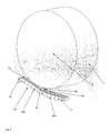
- FIG. 1 shows the inductor, i. an inductor loop, in Form of a pressure-form-wide hairpin inductor (line inductor) in the sense of a homogeneous heat input into the respective cylinder surface.
- inductor loops are different Use cases conceivable. So the inductor loop could be skewed to the circumferential direction of the printing forme cylinder to have a format variability to consider the printing form.
- the current density distribution in the printing form is influenced by two effects.
- self-induction in the interior of the printing plate causes eddy currents generated, which are superimposed on the primary current and to a current displacement lead the printing form surface. With increasing frequency, the current flows in always thinning layers below the printing plate surface. This phenomenon is known as the skin effect.
- On the other hand forms around the current-carrying zones of the printing forme an alternating magnetic field, which is superimposed on the alternating magnetic field of the inductor. Thereby there is an additional current displacement in the printing plate and in the inductor. This is known as the proximity or proximity effect and has the consequence that with increasing distance between inductor and printing form the heating zone becomes wider.
- magnetic field around the inductor loop leading building blocks are made of a material with high permeability, the each have at least two of the printing plate surface facing end faces, to form a space for a magnetic field for energy extraction.
- Figure 1 shows in section an inductor 2 with an inductor loop 2a, 2b, the tangential forming a minimum gap 11 on the printing form surface 1 at one of the contact points 24a, b; 25a, b (FIG. 3).
- the inductor 2 is a current-carrying conductor loop 2a, 2b by means of a copper tube guided and embedded in the magnetic field leading block 3 of the inductor 2.
- Each module 3 has at least two end faces 6a, 6b of a pole piece, as shown Embodiment, the module 3 is formed in E-shape, so that three Face surfaces 6a, 6b, 6c of the pressure surface 1 facing and between the End surfaces 6a, b, c, the conductor loop 2a, b is guided.
- the or the blocks 3 are intended according to the invention of a material with high Permeability exist. Particularly suitable for this are ferrites, i. sintered electrotechnical special masses with increased resistivity of the Core material. They are known to serve in particular to the core of the Coils of transformers are more visible at high frequencies to reduce passing losses.
- Ferrites are oxide sintered materials such as MeO.Fe 2 O 3 , where Me may be, for example, Cn, Mg, Ba, Zn, Cd, Mn, Co or Ni.
- the E-shaped component 3 is everted as the conductor loop 2 a, 2 b Pole shoe with four end faces 7a, 7b, 7c, 7d mentioned, each with each other two end faces 7a, 7c and 7b, 7d perpendicular to the printing form surface first aligned, between each of which is a magnetic Field 4a, 4b forms, so that there heating zones 5a, 5b over a smaller Slit 11 because of the highly compressed magnetic field 4a, 4b significantly in width are reduced.
- the permeability is the product of the magnetic field constant and the Permeability of the material.
- FIG. 3 shows the inductor 20 according to the invention in V-shape.
- the V-shape is carried out by means of two legs 20a, 20b, which are just V-shaped to the Durckformober Structure 1 are employed tangentially, the legs 20a, 20b to Formation of the pressure molding surface 1 encompassing V connected to each other are.
- Each leg 20a, 20b of the V-shape results for every possible printing plate diameter, for example, indicated by 21 and 22, a point of contact 24a or 25a or 24b or 25b, where the conditions for the energy input are optimal. If this Induktorform additionally according to the invention with the above-described materials, which have a high permeability, equipped, the characteristics of the independence of printing plate diameter can (Format variability) and the design of the heating zones 5a, 5b the printing form surface are optimally combined.
- FIG 4 illustrates once again that each leg 2, 20 of the inductor 2 from a Variety of identical blocks 3 is composed as a link chain.
- Everyone Building block 3 is a commercial E-shaped ferrite whose magnetic poles forming end faces 6a, b, c or 7a-d in the manner described above ausgestaltbar are.
- any suitable end face design is conceivable, however At least two end faces are required to make room for a magnetic Field, which in turn forms warming zones.
- the targeted adaptation or finding a suitable Induktorform was a essential component of the present invention.
- forms of the inductor or inductor loops are for different applications conceivable.
- the inductor 2, 20 with inductor loops in unit to traverse with an RF part in the axial direction of the rotary printing form 10.
- the HF part and inductor would not have to be a structural unit, it can also, the RF part to be stationary in the printing press and flexible Lines to be coupled to the traversable inductor.
- the inductor in the finger guard in the nip between a printing plate on a printing form cylinder and a blanket cylinder integrate, which would be a particularly space-saving variant executable.
- the present device for inductive thermal energy coupling is especially for one imaged by a laser-induced thermal transfer process
- the imaging unit is by means of a special mechanism on the one hand the printing form on and off and on the other hand, if the impression cylinder be offset from each other, for example, in the sense of observance of a format variability the printing form, of course, the imaging unit accordingly with traversable.
- the inductor is mitverfahrbar, what he in an advantageous Way associated with its RF part permanently associated with the imaging unit is.
Landscapes
- Physics & Mathematics (AREA)
- Electromagnetism (AREA)
- General Induction Heating (AREA)
- Fixing For Electrophotography (AREA)
- Manufacture Or Reproduction Of Printing Formes (AREA)
Abstract
Description
- Figur 1:
- den prinzipiellen Aufbau eines erfindungsgemäßen Induktors aus Induktorschleife und dem diese umgebende, das Magnetfeld führende Bauteil zur thermischen Energieeinkopplung in die Druckformoberfläche,
- Figur 2:
- den Induktor gem. der Figur 1, jedoch mit variierter Abstandsgestaltung zwischen dem Magnetfeld führenden Bauteil und Druckformoberfläche,
- Figur 3:
- einen erfindungsgemäßen Induktor in V-Form zur Erzielung weiterer Berührungspunkte, und
- Figur 4:
- einen Induktor gem. der Figur 3, der aus einer Vielzahl baugleicher ferritischer Bausteine als Gliederkette, die die Induktorschleife umgeben, zusammengesetzt ist.
Claims (11)
- Einrichtung zur induktiven thermischen Energieeinkopplung zum Fixieren eines Bildes auf einer mittels eines digitalen Bebilderungssystems bebilderten rotierenden Druckform aus einem für eine Induktionserwärmung geeigneten Material, die mind. einen Induktor mit mind. einer Induktionsschleife, ein Hochfrequenz(HF)-Teil, das gemeinsam mit dem Induktor einen Schwingkreis bildet, und eine mittels für Hochfrequenz geeignete Versorgungsleitungen (HF-Leitungen) ankoppelbares Versorgungsteil umfasst und jede Induktorschleife in länglicher Form in etwa parallel zur Umfangsrichtung der rotierenden Druckform ausgerichtet ist, dadurch gekennzeichnet, dass um die Induktorschleife (2a,b) Magnetfeld führende Bausteine (3) aus einem Werkstoff mit hoher Permeabilität gestülpt sind, die jeweils mind. zwei Energie eines Magnetfelds (4a,b) in die Druckformoberfläche (1) einkoppelnde Stirnflächen (6a,b bzw. 7a,c oder 7b,d) aufweisen.
- Einrichtung nach Anspruch 1, dadurch gekennzeichnet, dass der Induktor (2,20) aus einer Vielzahl baugleicher Bausteine (3), die als Gliederkette die Induktorschleife (2a,b) umstülpen, zusammengesetzt ist.
- Einrichtung nach Anspruch 1 oder 2, dadurch gekennzeichnet, dass der Induktor (2,20) zur zonalen Erwärmung der Druckformoberfläche (1) tangential unter Ausbildung eines minimalen Spaltes (11) an dieser ausgerichtet ist.
- Einrichtung nach Anspruch 3, dadurch gekennzeichnet, dass der Induktor (20) in Form zweier Schenkel (20a,20b) ausgeführt ist, die jeweils V-förmig an der Druckformoberfläche (1) tangential anstellbar sind, wobei die Schenkel (20a,20b) zur Ausbildung des V miteinander verbunden sind.
- Einrichtung nach Anspruch 1 bis 4, dadurch gekennzeichnet, dass je Induktor (2,20) mehrere, insbesondere zwei Induktorschleifen (2a,b) vorgesehen sind.
- Einrichtung nach einem der vorangehenden Ansprüche, dadurch gekennzeichnet, dass die das Magnetfeld führenden Bausteine (3) Ferrite sind.
- Einrichtung nach Anspruch 1 bis 6, dadurch gekennzeichnet, dass die Bausteine (3) handelsübliche Ferrite in E-Form sind, die mind. drei zur Druckformoberfläche (1) hinweisende Stirnflächen (6a,b,c) aufweisen.
- Einrichtung nach Anspruch 1 bis 6, dadurch gekennzeichnet, dass die Bausteine (3) Ferrite in E-Form sind, die vier Stirnflächen (7a-d) aufweisen, um die Magnetfelder (4a,b) zu komprimieren und die Erwärmungszonen (5a,b) zu verkleinern.
- Einrichtung nach Anspruch 1, dadurch gekennzeichnet, dass zur homogenen und zonalen Erwärmung der Druckformoberfläche (1) der Induktor (2,20) in Achsrichtung der rotierenden Druckform (10) traversierbar ist.
- Einrichtung nach Anspruch 1, dadurch gekennzeichnet, dass das HF-Teil ortsfest in der Druckmaschine angeordnet ist und über flexible Leitungen an den Induktor anschließbar ist.
- Einrichtung nach Anspruch 1, dadurch gekennzeichnet, dass das HF-Teil mit dem Induktor eine bauliche Einheit bildet und ebenfalls in Achsrichtung der rotierenden Druckform (10) traversierbar ist.
Applications Claiming Priority (2)
| Application Number | Priority Date | Filing Date | Title |
|---|---|---|---|
| DE102004023127A DE102004023127B3 (de) | 2004-05-11 | 2004-05-11 | Einrichtung zur induktiven thermischen Energieeinkopplung zum Fixieren eines Bildes |
| DE102004023127 | 2004-05-11 |
Publications (2)
| Publication Number | Publication Date |
|---|---|
| EP1596636A1 true EP1596636A1 (de) | 2005-11-16 |
| EP1596636B1 EP1596636B1 (de) | 2009-12-02 |
Family
ID=34936245
Family Applications (1)
| Application Number | Title | Priority Date | Filing Date |
|---|---|---|---|
| EP05009969A Expired - Lifetime EP1596636B1 (de) | 2004-05-11 | 2005-05-06 | Einrichtung zur induktiven thermischen Energieeinkopplung zum Fixieren eines Bildes |
Country Status (6)
| Country | Link |
|---|---|
| US (1) | US7411164B2 (de) |
| EP (1) | EP1596636B1 (de) |
| JP (1) | JP4299265B2 (de) |
| CN (1) | CN1701957A (de) |
| CA (1) | CA2507087C (de) |
| DE (2) | DE102004023127B3 (de) |
Families Citing this family (3)
| Publication number | Priority date | Publication date | Assignee | Title |
|---|---|---|---|---|
| DE102009010625A1 (de) * | 2009-02-26 | 2010-09-09 | OCé PRINTING SYSTEMS GMBH | Vorrichtung und Verfahren zum Trocknen einer bedruckten Bedruckstoffbahn |
| CN105705317B (zh) * | 2013-11-29 | 2018-09-28 | 利乐拉瓦尔集团及财务有限公司 | 感应加热装置 |
| DE102015200114B4 (de) * | 2015-01-08 | 2018-12-20 | Koenig & Bauer Ag | Verfahren zum Wiederbenutzen einer Druckplatte |
Citations (3)
| Publication number | Priority date | Publication date | Assignee | Title |
|---|---|---|---|---|
| US6195525B1 (en) * | 1998-12-21 | 2001-02-27 | Fuji Xerox Co., Ltd. | Electromagnetic induction heating device and image recording device using the same |
| DE10008213A1 (de) * | 2000-02-23 | 2001-08-30 | Roland Man Druckmasch | Einrichtung zur thermischen Energieeinkopplung |
| US20020141794A1 (en) * | 2001-03-28 | 2002-10-03 | Hirst B. Mark | Fusing system having electromagnetic heating |
Family Cites Families (3)
| Publication number | Priority date | Publication date | Assignee | Title |
|---|---|---|---|---|
| US3526708A (en) * | 1965-11-09 | 1970-09-01 | Heller William C Jun | Magnetic through-field apparatus and process for printing by imbedding particles in a record medium |
| SE422136B (sv) * | 1979-10-23 | 1982-02-15 | Tetra Pak Int | Anordning for forsegling av termoplastbelagt forpackningsmaterial |
| WO1992009397A1 (en) | 1990-11-30 | 1992-06-11 | Heron Technologies, Inc. | Induction dryer and magnetic separator |
-
2004
- 2004-05-11 DE DE102004023127A patent/DE102004023127B3/de not_active Expired - Fee Related
-
2005
- 2005-05-05 US US11/122,544 patent/US7411164B2/en not_active Expired - Fee Related
- 2005-05-06 DE DE502005008605T patent/DE502005008605D1/de not_active Expired - Lifetime
- 2005-05-06 EP EP05009969A patent/EP1596636B1/de not_active Expired - Lifetime
- 2005-05-10 JP JP2005137795A patent/JP4299265B2/ja not_active Expired - Fee Related
- 2005-05-11 CN CN200510068788.0A patent/CN1701957A/zh active Pending
- 2005-05-11 CA CA002507087A patent/CA2507087C/en not_active Expired - Fee Related
Patent Citations (3)
| Publication number | Priority date | Publication date | Assignee | Title |
|---|---|---|---|---|
| US6195525B1 (en) * | 1998-12-21 | 2001-02-27 | Fuji Xerox Co., Ltd. | Electromagnetic induction heating device and image recording device using the same |
| DE10008213A1 (de) * | 2000-02-23 | 2001-08-30 | Roland Man Druckmasch | Einrichtung zur thermischen Energieeinkopplung |
| US20020141794A1 (en) * | 2001-03-28 | 2002-10-03 | Hirst B. Mark | Fusing system having electromagnetic heating |
Also Published As
| Publication number | Publication date |
|---|---|
| EP1596636B1 (de) | 2009-12-02 |
| US20050264631A1 (en) | 2005-12-01 |
| US7411164B2 (en) | 2008-08-12 |
| JP2005324549A (ja) | 2005-11-24 |
| CA2507087C (en) | 2008-12-23 |
| CA2507087A1 (en) | 2005-11-11 |
| DE502005008605D1 (de) | 2010-01-14 |
| JP4299265B2 (ja) | 2009-07-22 |
| DE102004023127B3 (de) | 2006-02-02 |
| CN1701957A (zh) | 2005-11-30 |
Similar Documents
| Publication | Publication Date | Title |
|---|---|---|
| EP2463869B1 (de) | Induktives Bauelement mit verbesserten Kerneigenschaften | |
| DE69624648T2 (de) | Induktionsheizspule zur Verhütung von zirkulierenden Strömen in Induktionsheizstössen für Stranggussprodukte | |
| DE102016108646B4 (de) | Elektrodynamische Bremse | |
| DE748787C (de) | Als Vierpol geschaltete Laufzeitspule | |
| DE102005047451A1 (de) | Synchronmaschine | |
| EP2546842A2 (de) | Spule zur Strombegrenzung | |
| DE102005061670B4 (de) | Verfahren zum induktiven Erwärmen eines Werkstücks | |
| EP1596636B1 (de) | Einrichtung zur induktiven thermischen Energieeinkopplung zum Fixieren eines Bildes | |
| DE102011085680B4 (de) | Heizspule für ein Einspritzventil und Einspritzventil | |
| EP1849169B1 (de) | Transformatorkern mit magnetischer abschirmung | |
| EP2867906B1 (de) | Induktives bauteil | |
| EP0511595A1 (de) | Durchflussmessgerät | |
| EP3529054B1 (de) | Induktives verschweissen von kunststoffrohren mittels einer spulenanordnung mit mehreren einzelspulen | |
| EP3324703A1 (de) | Induktionsheizeinrichtung für industrielle zwecke | |
| DE2411139C3 (de) | Induktiver Meßwertgeber zum berührungslosen Erfassen des Abstandes zweier Objekte | |
| EP1772940A2 (de) | Rotierübertrager zur Übertragung von elektrischer Energie oder Information | |
| EP0637897A2 (de) | Vorrichtung zum induktiven Längsfelderwärmen von flachem Metallgut | |
| DE886358C (de) | Vorrichtung zum induktiven Waermebehandeln metallischer Werkstuecke | |
| DE2925654A1 (de) | Weggeber | |
| DE102012021087A1 (de) | Verfahren zur induktiven Erwärmung von Werkstücken | |
| DE862814C (de) | Vorrichtung zum elektroinduktiven Erhitzen von Werkstuecken | |
| DE1014244B (de) | Durch Dauermagneten vormagnetisierter ferromagnetischer Spulenkern | |
| DE1589595C (de) | Vorrichtung zum Erzeugen eines starken Magnetfeldes | |
| DE102017223839A1 (de) | Magnetkern mit Rückschlussschenkel | |
| DE29609289U1 (de) | Magnetanordnung für ein NMR-Tomographiesystem, insbesondere für Haut- und Oberflächenuntersuchungen |
Legal Events
| Date | Code | Title | Description |
|---|---|---|---|
| PUAI | Public reference made under article 153(3) epc to a published international application that has entered the european phase |
Free format text: ORIGINAL CODE: 0009012 |
|
| AK | Designated contracting states |
Kind code of ref document: A1 Designated state(s): AT BE BG CH CY CZ DE DK EE ES FI FR GB GR HU IE IS IT LI LT LU MC NL PL PT RO SE SI SK TR |
|
| AX | Request for extension of the european patent |
Extension state: AL BA HR LV MK YU |
|
| 17P | Request for examination filed |
Effective date: 20060511 |
|
| AKX | Designation fees paid |
Designated state(s): CH DE FR GB LI |
|
| 17Q | First examination report despatched |
Effective date: 20070301 |
|
| RAP1 | Party data changed (applicant data changed or rights of an application transferred) |
Owner name: MANROLAND AG |
|
| GRAP | Despatch of communication of intention to grant a patent |
Free format text: ORIGINAL CODE: EPIDOSNIGR1 |
|
| GRAS | Grant fee paid |
Free format text: ORIGINAL CODE: EPIDOSNIGR3 |
|
| GRAA | (expected) grant |
Free format text: ORIGINAL CODE: 0009210 |
|
| AK | Designated contracting states |
Kind code of ref document: B1 Designated state(s): CH DE FR GB LI |
|
| REG | Reference to a national code |
Ref country code: GB Ref legal event code: FG4D Free format text: NOT ENGLISH |
|
| REG | Reference to a national code |
Ref country code: CH Ref legal event code: NV Representative=s name: E. BLUM & CO. AG PATENT- UND MARKENANWAELTE VSP Ref country code: CH Ref legal event code: EP |
|
| REF | Corresponds to: |
Ref document number: 502005008605 Country of ref document: DE Date of ref document: 20100114 Kind code of ref document: P |
|
| PLBE | No opposition filed within time limit |
Free format text: ORIGINAL CODE: 0009261 |
|
| STAA | Information on the status of an ep patent application or granted ep patent |
Free format text: STATUS: NO OPPOSITION FILED WITHIN TIME LIMIT |
|
| 26N | No opposition filed |
Effective date: 20100903 |
|
| PGFP | Annual fee paid to national office [announced via postgrant information from national office to epo] |
Ref country code: FR Payment date: 20110607 Year of fee payment: 7 Ref country code: CH Payment date: 20110524 Year of fee payment: 7 |
|
| PGFP | Annual fee paid to national office [announced via postgrant information from national office to epo] |
Ref country code: GB Payment date: 20110520 Year of fee payment: 7 |
|
| PGFP | Annual fee paid to national office [announced via postgrant information from national office to epo] |
Ref country code: DE Payment date: 20110520 Year of fee payment: 7 |
|
| REG | Reference to a national code |
Ref country code: CH Ref legal event code: PL |
|
| GBPC | Gb: european patent ceased through non-payment of renewal fee |
Effective date: 20120506 |
|
| PG25 | Lapsed in a contracting state [announced via postgrant information from national office to epo] |
Ref country code: CH Free format text: LAPSE BECAUSE OF NON-PAYMENT OF DUE FEES Effective date: 20120531 Ref country code: LI Free format text: LAPSE BECAUSE OF NON-PAYMENT OF DUE FEES Effective date: 20120531 |
|
| REG | Reference to a national code |
Ref country code: FR Ref legal event code: ST Effective date: 20130131 |
|
| REG | Reference to a national code |
Ref country code: DE Ref legal event code: R119 Ref document number: 502005008605 Country of ref document: DE Effective date: 20121201 |
|
| PG25 | Lapsed in a contracting state [announced via postgrant information from national office to epo] |
Ref country code: FR Free format text: LAPSE BECAUSE OF NON-PAYMENT OF DUE FEES Effective date: 20120531 Ref country code: GB Free format text: LAPSE BECAUSE OF NON-PAYMENT OF DUE FEES Effective date: 20120506 |
|
| PG25 | Lapsed in a contracting state [announced via postgrant information from national office to epo] |
Ref country code: DE Free format text: LAPSE BECAUSE OF NON-PAYMENT OF DUE FEES Effective date: 20121201 |