EP1596214A1 - Magnetsystem mit einem Pulsrohrkühler - Google Patents
Magnetsystem mit einem Pulsrohrkühler Download PDFInfo
- Publication number
- EP1596214A1 EP1596214A1 EP05009743A EP05009743A EP1596214A1 EP 1596214 A1 EP1596214 A1 EP 1596214A1 EP 05009743 A EP05009743 A EP 05009743A EP 05009743 A EP05009743 A EP 05009743A EP 1596214 A1 EP1596214 A1 EP 1596214A1
- Authority
- EP
- European Patent Office
- Prior art keywords
- magnetic
- magnet system
- shield
- magnet
- regenerator material
- Prior art date
- Legal status (The legal status is an assumption and is not a legal conclusion. Google has not performed a legal analysis and makes no representation as to the accuracy of the status listed.)
- Granted
Links
- 239000000463 material Substances 0.000 claims abstract description 138
- 239000000696 magnetic material Substances 0.000 claims abstract description 55
- 238000000034 method Methods 0.000 claims abstract description 6
- 230000005415 magnetization Effects 0.000 claims description 21
- 230000035699 permeability Effects 0.000 claims description 17
- 230000006698 induction Effects 0.000 claims description 14
- 239000004020 conductor Substances 0.000 claims description 13
- 238000001816 cooling Methods 0.000 claims description 13
- 239000007788 liquid Substances 0.000 claims description 13
- 239000002887 superconductor Substances 0.000 claims description 13
- IJGRMHOSHXDMSA-UHFFFAOYSA-N Atomic nitrogen Chemical compound N#N IJGRMHOSHXDMSA-UHFFFAOYSA-N 0.000 claims description 6
- 230000005855 radiation Effects 0.000 claims description 6
- 238000001704 evaporation Methods 0.000 claims description 5
- 239000001307 helium Substances 0.000 claims description 5
- 229910052734 helium Inorganic materials 0.000 claims description 5
- SWQJXJOGLNCZEY-UHFFFAOYSA-N helium atom Chemical compound [He] SWQJXJOGLNCZEY-UHFFFAOYSA-N 0.000 claims description 5
- 238000005481 NMR spectroscopy Methods 0.000 claims description 4
- 230000008020 evaporation Effects 0.000 claims description 3
- 229910052757 nitrogen Inorganic materials 0.000 claims description 3
- 238000004611 spectroscopical analysis Methods 0.000 claims description 3
- 238000002595 magnetic resonance imaging Methods 0.000 claims description 2
- 239000011343 solid material Substances 0.000 claims description 2
- 230000001629 suppression Effects 0.000 claims description 2
- 238000012216 screening Methods 0.000 abstract description 2
- 230000008901 benefit Effects 0.000 description 8
- 230000000694 effects Effects 0.000 description 6
- 239000007787 solid Substances 0.000 description 5
- 230000004907 flux Effects 0.000 description 3
- 230000001965 increasing effect Effects 0.000 description 3
- 230000009467 reduction Effects 0.000 description 3
- 229920006395 saturated elastomer Polymers 0.000 description 3
- 230000007704 transition Effects 0.000 description 3
- YBJHBAHKTGYVGT-ZKWXMUAHSA-N (+)-Biotin Chemical compound N1C(=O)N[C@@H]2[C@H](CCCCC(=O)O)SC[C@@H]21 YBJHBAHKTGYVGT-ZKWXMUAHSA-N 0.000 description 2
- 230000001419 dependent effect Effects 0.000 description 2
- 238000009413 insulation Methods 0.000 description 2
- 230000000737 periodic effect Effects 0.000 description 2
- 238000010791 quenching Methods 0.000 description 2
- 230000000171 quenching effect Effects 0.000 description 2
- FEPMHVLSLDOMQC-UHFFFAOYSA-N virginiamycin-S1 Natural products CC1OC(=O)C(C=2C=CC=CC=2)NC(=O)C2CC(=O)CCN2C(=O)C(CC=2C=CC=CC=2)N(C)C(=O)C2CCCN2C(=O)C(CC)NC(=O)C1NC(=O)C1=NC=CC=C1O FEPMHVLSLDOMQC-UHFFFAOYSA-N 0.000 description 2
- 238000004804 winding Methods 0.000 description 2
- 230000002411 adverse Effects 0.000 description 1
- 230000015572 biosynthetic process Effects 0.000 description 1
- 230000008859 change Effects 0.000 description 1
- 230000007423 decrease Effects 0.000 description 1
- 230000005347 demagnetization Effects 0.000 description 1
- 239000011888 foil Substances 0.000 description 1
- 230000001939 inductive effect Effects 0.000 description 1
- 238000005259 measurement Methods 0.000 description 1
- 230000003068 static effect Effects 0.000 description 1
- 239000000725 suspension Substances 0.000 description 1
- 230000036962 time dependent Effects 0.000 description 1
Images


Classifications
-
- G—PHYSICS
- G01—MEASURING; TESTING
- G01R—MEASURING ELECTRIC VARIABLES; MEASURING MAGNETIC VARIABLES
- G01R33/00—Arrangements or instruments for measuring magnetic variables
- G01R33/20—Arrangements or instruments for measuring magnetic variables involving magnetic resonance
- G01R33/28—Details of apparatus provided for in groups G01R33/44 - G01R33/64
- G01R33/38—Systems for generation, homogenisation or stabilisation of the main or gradient magnetic field
- G01R33/381—Systems for generation, homogenisation or stabilisation of the main or gradient magnetic field using electromagnets
- G01R33/3815—Systems for generation, homogenisation or stabilisation of the main or gradient magnetic field using electromagnets with superconducting coils, e.g. power supply therefor
-
- F—MECHANICAL ENGINEERING; LIGHTING; HEATING; WEAPONS; BLASTING
- F25—REFRIGERATION OR COOLING; COMBINED HEATING AND REFRIGERATION SYSTEMS; HEAT PUMP SYSTEMS; MANUFACTURE OR STORAGE OF ICE; LIQUEFACTION SOLIDIFICATION OF GASES
- F25B—REFRIGERATION MACHINES, PLANTS OR SYSTEMS; COMBINED HEATING AND REFRIGERATION SYSTEMS; HEAT PUMP SYSTEMS
- F25B2309/00—Gas cycle refrigeration machines
- F25B2309/14—Compression machines, plants or systems characterised by the cycle used
- F25B2309/1415—Pulse-tube cycles characterised by regenerator details
-
- F—MECHANICAL ENGINEERING; LIGHTING; HEATING; WEAPONS; BLASTING
- F25—REFRIGERATION OR COOLING; COMBINED HEATING AND REFRIGERATION SYSTEMS; HEAT PUMP SYSTEMS; MANUFACTURE OR STORAGE OF ICE; LIQUEFACTION SOLIDIFICATION OF GASES
- F25B—REFRIGERATION MACHINES, PLANTS OR SYSTEMS; COMBINED HEATING AND REFRIGERATION SYSTEMS; HEAT PUMP SYSTEMS
- F25B9/00—Compression machines, plants or systems, in which the refrigerant is air or other gas of low boiling point
- F25B9/14—Compression machines, plants or systems, in which the refrigerant is air or other gas of low boiling point characterised by the cycle used, e.g. Stirling cycle
- F25B9/145—Compression machines, plants or systems, in which the refrigerant is air or other gas of low boiling point characterised by the cycle used, e.g. Stirling cycle pulse-tube cycle
Definitions
- the invention relates to a magnet system with a magnet arrangement, a working volume and a pulse tube refrigerator with magnetic regenerator material.
- pulse tube coolers for cooling elements of a magnet arrangement
- the pulse tube cooler is used to bring the helium bath to temperatures below 4.2K.
- the magnetic coils located therein can generate a higher field than at 4.2 K, because at lower temperatures higher currents can flow through the superconductor.
- a magnet arrangement with a piston refrigerator which comprises a slide made of materials with magnetic phase transition.
- a superconducting sleeve surrounding the refrigerator is proposed, which is arranged between the cold end of the refrigerator and the examination volume.
- the superconducting sleeve surrounds 90 ° to 270 ° of the cold end of the refrigerator. Due to the magnetic interference field of the regenerator material, a magnetic field opposite the interference field is induced in the sleeve, which is intended to keep the magnetic flux through the sleeve constant and thus to compensate for the interference field.
- EP 0 905 524 discloses a magnet system having a superconducting magnet arrangement and a pulse tube cooler.
- the pulse tube refrigerator is arranged in a suspension tube of the system. He can liquefy an evaporating cryogenic liquid again.
- Pulse tube coolers have much less vibration compared to other coolers on, which is a major advantage in susceptible magnetic systems.
- temperatures of and under 4.2 K of interest are possible temperatures of and under 4.2 K of interest.
- Particularly high cooling capacities have in this Temperature range pulse tube cooler with magnetic regenerator materials.
- This good cooling performance is due to the great heat capacity of the rare earths near her attributed to magnetic phase transition. Because of this phase transition The rare earths are magnetized by the stray field of the magnet arrangement. Within a cooling cycle, the temperature also changes magnetic properties of the regenerator material. His magnetization in the Stray field of the magnet arrangement thus changes periodically.
- Object of the present invention is to propose a magnet system, the equipped with a pulse tube cooler with magnetic regenerator material and still a stable, temporally constant magnetic field in the working volume realized.
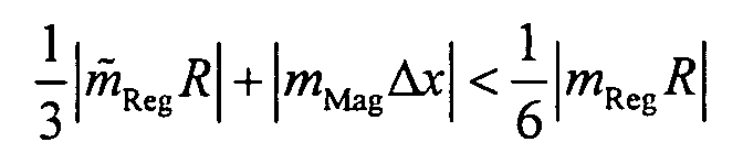
- a shield of magnetic material which reduces the stray field of the magnet assembly at the location of the magnetic regenerator material and is characterized in that where m Mag is the dipole moment of the magnetic material of the shield, ⁇ x the vibration amplitude of the magnetic material of the shield, m Reg is the amplitude of the dipole variations of the magnetic regenerator material in a cycle without magnetic shielding, stands for the amplitude of the dipole variations of the magnetic regenerator material in a cycle with magnetic shielding and R for the mean distance of the magnetic regenerator material to the working volume.
- the inventive shield of magnetic material the Stray field of the magnet assembly at the location of the magnetic regenerator material be shielded.
- the dipole variations of the magnetic Regenerator material reduces and the resulting electromagnetic Disturbances in the working volume of the magnet assembly efficiently suppressed become.
- Particularly suitable for shielding the magnetic regenerator material is soft magnetic material that attracts field lines and so the Magnetic field shields in its interior.
- the material of the hollow cylinder is magnetized and forms a magnetic dipole.
- a pulse tube refrigerator is one of the lowest vibration radiators, there are smaller vibrations that can be transmitted to the shield of magnetic material.
- the magnetic material shield according to the invention can be regarded as a vibrating magnetic dipole, which generates a periodic electromagnetic disturbance in the working volume of the magnet arrangement, which under certain circumstances can be greater than the original disturbance of the magnetic regenerator material. To avoid this problem, the amount of field disturbance from the magnetic regenerator material and from the magnetic shield in the working volume of the magnet assembly must be estimated and the parameters of the shield appropriately designed.
- the disturbance generated due to the vibrating shield in the working volume is at least a factor of two smaller than that which the magnetic regenerator material would produce without magnetic shielding.
- the magnet system according to the invention therefore has, compared with known magnet systems, a considerable reduction of the disturbances occurring in the working volume which result from the operation of a pulse tube cooler with magnetic regenerator material.
- a field of application of pulse tube coolers in the magnet system according to the invention includes, for example, the cooling of a superconducting magnet arrangement or Parts of a cryostat in which the superconducting magnet assembly is located.
- the low temperatures are in such a magnet system due to the Superconducting properties of the wires needed.
- Such magnet systems are For example, used to generate extremely high, homogeneous magnetic fields.
- the cooling of Measuring devices in the working volume of the magnet arrangement sought with the Advantage of reducing the thermal noise in the signal.
- the cooling of the measuring device Noise levels in the signal are such that significantly shorter measurement times possible become.
- the magnetic material of the shield has a maximum permeability ⁇ max of at least 10,000.
- the maximum permeability is the largest value of the relative permeability, which is a function of the field. Since the relative permeability is a measure of the shielding effect, a magnetic shield of high maximum permeability material can best shield the stray field of the magnet assembly at the location of the magnetic regenerator material. Another advantage arises from the fact that the magnetic shield, as long as it is not in the magnetic saturation, residual disturbances that may still arise in the magnetic regenerator material, counteract by variations of their magnetization and thus can further reduce the Störamplitude in the working volume.
- the saturation induction of the magnetic material at least 1 Tesla, preferably 2 Tesla. So can one relatively strong stray field of the magnet assembly at the location of the magnetic regenerator material With little shielding an opposing field can be built. A high saturation induction also causes the magnetic material not easy is driven into magnetic saturation. The magnetic material shields like this on the one hand, the stray field of the magnet arrangement at the location of the magnetic regenerator material still off and on the other hand, the possibly still in the magnetic regenerator material resulting interference by variations counteract its magnetization in the working volume.
- the magnetic shield comprises at least one hollow cylinder containing the magnetic regenerator material to be screened encloses.
- the regenerator mostly the geometry of a cylinder
- a hollow cylinder is the simplest possible embodiment for the magnetic shielding.
- shielding materials are in films produced. The winding of foil on a cylinder carrier leads to simple Way to the desired geometry.
- the inner part of the hollow cylinder consists of material with high permeability ⁇ max > 10000, while the outer part consists of material with high saturation induction> 1 Tesla. Due to the high saturation induction of the outer material, a strong reduction of the stray field of the magnet arrangement is achieved, as a result of which the inner part of the hollow cylinder with the high permeability is already in a greatly reduced field, which can then be optimally shielded. In particular, a strong stray field of the magnet arrangement can be well shielded at the location of the regenerator and thus the formation of an electromagnetic disturbance in the magnetic regenerator material can be suppressed.
- the outer diameter of the hollow cylinder should be smaller than 1.5 times the outer diameter of the magnetic regenerator material to be shielded.
- the smaller the outer diameter of the hollow cylinder the smaller the dipole moment of the magnetic material of which the hollow cylinder is made, so that the required condition, namely that is satisfied.
- a small outer diameter of the hollow cylinder also causes the soft magnetic material is not magnetically saturated. Therefore, on the one hand, the stray field of the magnet arrangement at the location of the magnetic regenerator material is still shielded and on the other hand, any disturbances that may still arise in the magnetic regenerator material can be reduced by variations in the magnetization of the hollow cylinder in the working volume.
- the magnet system extends beyond at least one axial end of the hollow cylinder to be shielded magnetic regenerator material at least one third of the inside diameter of the hollow cylinder.
- the magnetic regenerator material to be shielded comprises only areas the regenerator material, where magnetization fluctuations take place, more than 10% of the maximum magnetization fluctuation occurring during regenerator operation within the total regenerator material. Consequently the volume of the magnetic material of the shield becomes a portable one Minimum reduced, so that on the one hand material costs can be saved and, on the other hand, the disturbances due to the vibrations of the shield be minimized.
- At least a part of the magnetic Material is not in magnetic saturation, as a material in the magnetic saturation part of the stray field of the magnet assembly can not shield. Also disorders that may be in the regenerator material can still arise through a material in the magnetic saturation in the working volume can not be compensated.
- the shield made of magnetic material Temperaturstabilisert, in particular thermally conductive with a radiation shield, a cold stage of the pulse tube refrigerator or a cryogenic liquid container connected is. This is especially interesting when the shield is close located on the magnetic regenerator material, as in the magnetic Regenerator material occurring temperature fluctuations also on the magnetic material could transmit the shield. With their temperature-dependent magnetic properties would otherwise be the magnetic shielding a time-dependent magnetic dipole and would be undesirable in the working volume generate electromagnetic interference.
- the shield can be made of magnetic material from magnetic Regenerator material can be thermally insulated. Thermal insulation includes the Reduction of heat conduction, heat radiation and / or convection.
- a shield of electrical good conductive material provided around the magnetic regenerator material. This allows the remaining despite the magnetic shield remaining Interference can be compensated. In this way, for example, vibrations the magnetic shield or any existing dipole fluctuations of the magnetic regenerator material by building up an opposing field be compensated by Ableströme in electrically highly conductive material.
- the shield made of electrically good conductive material parts with a cylindrical symmetry on, and the magnetic field changes of the magnetic regenerator material and / or the magnetic shield at the location of the electrically highly conductive Shielding show predominantly in the direction of the corresponding cylinder axis.
- a cylinder of electrically good conductive material can namely field fluctuations parallel to its axis best compensate for the outside, since the shielding currents flow freely on the cylinder, especially in the circumferential direction can.
- the electrically highly conductive material is advantageously around a cryogenic superconductor. Due to the vanishing resistance of a Superconductors, the induction currents are built up unhindered. Thus, you can occurring disturbances are optimally compensated.
- the use of a low-temperature superconductor conditionally, however, that this is a sufficiently low temperature is exposed. This low temperature can be achieved, for example, by thermal Contacting of the superconductor with a cold stage of the pulse tube cooler or with a cold container in the cryostat can be achieved.
- the electrically highly conductive material is a high-temperature superconductor is.
- the necessary temperature for example, by thermal Contacting of the superconductor with the first stage of a two-stage pulse tube cooler or be reached with a cold container in the cryostat.
- this is electrically good conductive material of solid material, for example of a cylindrical Block.
- the shielding currents can be in all directions flow, so that they can compensate for electromagnetic interference optimally.
- the electrically highly conductive forms Material a solenoid coil. Because superconductors in the form of ribbons or wires available, it makes sense to wind it with a solenoid coil.
- the superconducting magnet arrangement with Coils for stray field suppression is equipped.
- an active Shielding becomes the magnetic field at the location of the magnetic regenerator material and thus reduces the interference that occurs thereby, so that the previously merely described a magnetic material shielding device have to compensate reduced interference field.
- the magnetic field at the location of the magnetic regenerator material exceeds preferably not 10 mT. Such a field can with a reasonable Amount of soft magnetic material to be shielded.
- the superconducting magnet arrangement coils having the electromagnetic interference of the magnetic Suppress regenerator material. With such additional coils, the possibly still existing disturbances of the magnetic regenerator material be compensated in the working volume.
- the Superconducting magnet assembly comprises coils which the electromagnetic Suppress disturbances of the vibrating magnetic shield.
- the magnet system according to the invention contains Cryostat of the superconducting magnet assembly a radiation shield, which brings the pulse tube cooler to its operating temperature.
- a radiation shield By cooling the Radiation shield can be the energy input of the warm environment on the Superconducting magnet assembly can be reduced.
- cryostat of the superconducting magnet assembly a container with liquid Nitrogen, which the pulse tube cooler after evaporation at least partially liquefied, which reduces the consumption of liquid nitrogen or eliminated.
- Magnetic system is the evaporating liquid helium from Pulse tube cooler at least partially re-liquefied.
- the helium consumption be reduced or eliminated.
- the magnet assembly without Cryogenic liquid from the pulse tube cooler brought to its operating temperature and / or kept.
- the time-consuming and costly handling of cryogenic Liquids partially or completely avoided.
- the advantages of the magnet system according to the invention are particularly good Validity, if the superconducting magnet arrangement part of an apparatus for Nuclear magnetic resonance, in particular magnetic resonance imaging (MRI) or magnetic resonance spectroscopy (NMR) is, as in such apparatuses a particular stable magnetic field is needed.
- MRI magnetic resonance imaging
- NMR magnetic resonance spectroscopy
- the invention further includes a method of operating a magnet system according to any one of claims 17 to 20, wherein the superconducting material the shield inductively charged during charging of the magnet assembly becomes.
- the magnetic field at the location of the magnetic regenerator material r can be shielded.
- soft magnetic material which attracts field lines and thus shields the magnetic field in its interior.
- FIG. 1 shows a magnet system M according to the invention , in which a working volume V is located, with a two-stage pulse tube cooler P arranged away from the magnet system M and a magnetic shield m.
- the magnetic shield m encloses the magnetic regenerator material r of the second stage of the pulse tube cooler P and is shown here in a particularly simple embodiment, namely in the form of a hollow cylinder.
- This magnetic shield m may for example consist of soft magnetic material. Since soft magnetic material is often produced in sheet form, a cylindrical shape can be easily obtained by winding such a sheet on a cylinder support. By choosing the number of layers, the desired wall thickness of the magnetic shield m can be achieved. Since the BH curve of a soft magnetic material is temperature-dependent, temperature fluctuations of the magnetic shield must be avoided.
- a thermal insulation layer between the soft magnetic material and the magnetic regenerator material r can be provided; on the other hand, thermal contacting of the soft magnetic material with existing temperature-stable parts of the arrangement can lead to this goal.
- Temperature stable parts of the assembly may be, for example, a cryogenic liquid or a container cooled by it. Another possibility is provided by the ends of the pulse tube cooler, which have a defined temperature during operation.
- a hollow cylinder with inner diameter D, height L and wall thickness d is considered as the geometry of the soft magnetic material, although other geometries would also lead to similar results.
- the geometry of a solid cylinder with diameter D Reg and height L Reg is assumed for the magnetic regenerator material r, wherein this solid cylinder should be contained in the hollow cylinder of the magnetic material. It should be emphasized here that this solid cylinder comprises only that part of the magnetic regenerator material r in which the temperature fluctuations lead to appreciable fluctuations of the magnetization.
- the shielding factor S p 1 + 4 N ( S s -1) 1 + D 2 L with the so-called demagnetization factor N , which depends on the ratio L / D. It is assumed here that ⁇ r >> 1. This formula applies to cylinders closed on both sides and is therefore only valid for long hollow cylinders. Without going into detail, it can be seen that a good shielding effect with a high relative permeability ⁇ r can be achieved.
- Fig. 2 shows typical BH curves for soft magnetic materials with high maximum permeability (dashed graph) and high maximum saturation induction (solid graph).
- the very steep increase of the BH curve for materials with a high maximum permeability ⁇ max at already small field strengths H shows that such materials are suitable for the efficient shielding of small magnetic fields.
- such materials also have a small saturation induction B s (here: 0.8T).
- B s here: 0.8T
- Magnetic saturation means, however, that part of the magnetic field can penetrate into the interior of the hollow cylinder.
- either the wall thickness of the material can be increased, or a material with higher saturation induction (but smaller maximum permeability ⁇ max ) can be used.
- the BH curve of materials with higher saturation induction has a less steep slope, allowing only a less effective shielding to be achieved.
- a material with a high saturation induction can be used in the outer radial region of the hollow cylinder and a material with a high maximum permeability can be used in the inner radial region of the hollow cylinder.
- the outer region is driven by the stray field of the magnet assembly close to saturation, but the inner region is already in a greatly reduced field, which he can then optimally shield.
- Fig. 3b shows a representation of flux lines f in the vicinity of a cylindrical shield m of soft magnetic material.
- the field without a shield m would be made of soft magnetic material parallel to the axis of the cylinder.
- the concentrated field lines f at the axial edge of the hollow cylinder leave the shielding m of magnetic material again. There is even a field elevation instead, so the field is locally even larger than it was without shielding m. So that the magnetic field at the location of the magnetic regenerator material r is shielded, so the height L of the shield m must be greater than the height L reg of the magnetic regenerator material r.
- the magnetic field is typically shielded by at least a factor of 2 throughout the solid cylinder of the magnetic regenerator material r. If it projects more than 2D on both sides beyond the cylinder of the magnetic regenerator material r, the shielding effect can not be further improved.
- the material of the hollow cylindrical shield m is magnetized and forms a magnetic dipole.
- a pulse tube cooler P is one of the lowest vibration radiators ever, smaller vibrations are present.
- the hollow cylindrical shield m can be regarded as a vibrating magnetic dipole, which generates in the working volume of the magnet assembly M a periodic electromagnetic interference, which may be greater than the original disturbance of the magnetic regenerator material r. To avoid this problem, the amount of field disturbance from the magnetic regenerator material r and the magnetic shield m in the working volume V of the magnet assembly M must be estimated.
- the magnetic regenerator material r is a time-varying dipole because of temperature fluctuations.
- a mean susceptibility fluctuation with amplitude ⁇ in the volume of the magnetic regenerator material r during one cycle a dipole change with amplitude results
- ⁇ D Reg 2 4 L Reg
- B denotes the stray field of the magnet assembly M at the location of the magnetic regenerator material r.
- B denotes the stray field of the magnet assembly M at the location of the magnetic regenerator material r.
- the direction of this dipole fluctuation is that of the stray field of the magnet assembly M at the location of the magnetic regenerator material r.
- the disturbance generated due to the vibrating shield m in the working volume V is at least a factor of two smaller than that which the magnetic regenerator material r without magnetic shield m would produce.
- the magnetic shield m does not totally shield the stray field of the magnet assembly M at the location of the regenerator material, the contribution of the residual disturbance of the magnetic regenerator material r must still be added to the left side of the inequality. So you get more general the condition in which denotes the remaining dipole moment of the magnetic regenerator material r in the presence of the magnetic shield m.
- Table 1 shows two shielding variants, which differ by a factor of two in all geometrical sizes, which leads to the same shielding effect on the axis of the hollow cylindrical shield m.
- the magnetization of the hollow cylindrical shield m will be adjusted with sufficient permeability of the material in both shielding variants so that the stray field at the location of the magnetic regenerator material r is well compensated, so that can be neglected below.
- the magnetization in the material can be calculated.
- a magnetization of about 2.4 * 10 5 [A / m] results, in the middle of about 5.6 * 10 5 [A / m].
- the second shielding variant can be assumed that the electromagnetic interference, which due to the vibrations of the magnetic shielding material in the working volume V are about the same size as the original electromagnetic Disturbances of the magnetic regenerator material r that you wanted to shield.
- the second screening variant therefore does not fulfill the objective of reducing the electromagnetic disturbances in working volume V.
- the in the magnetic regenerator material r and in the magnetic material of Shielding m still arising interference can be controlled by a good Shield (not shown), both enclosing, be further screened.
- the highly conductive shield may be superconductive or normally conductive.
- a normally conductive shield is that only shielding currents flow and so no permanent currents are present, the homogeneity in the Working volume V or the stray field of the magnet assembly M adversely affect can. Also, any quenching hazard with a normally conductive shield be excluded.
Landscapes
- Physics & Mathematics (AREA)
- Electromagnetism (AREA)
- Condensed Matter Physics & Semiconductors (AREA)
- General Physics & Mathematics (AREA)
- Shielding Devices Or Components To Electric Or Magnetic Fields (AREA)
- Magnetic Resonance Imaging Apparatus (AREA)
- Containers, Films, And Cooling For Superconductive Devices (AREA)
Abstract


Description



- Fig. 1
- ein erfindungsgemäßes Magnetsystem mit Pulsrohrkühler und magnetischer Abschirmung in Form eines Zylinders;
- Fig. 2
- typische BH-Kurven eines weichmagnetischen Materials mit hoher maximaler Permeabilität und eines weichmagnetischen Materials mit hoher maximaler Sättigungsinduktion;
- Fig. 3b
- eine Darstellung von Flusslinien in der Nähe einer zylindrischen Abschirmung m aus weichmagnetischem Material;
- Fig. 3a
- einen vergrößerten Ausschnitt aus Fig. 3b; und
- Tab. 1
- zwei Abschirmvarianten, die sich in ihren geometrischer Größen unterscheiden.

Claims (30)
- Magnetsystem mit einer Magnetanordnung (M), einem Arbeitsvolumen (V) und einem Pulsrohrkühler (P) mit magnetischem Regeneratormaterial (r),
dadurch gekennzeichnet, dass eine Abschirmung (m) aus magnetischem Material vorgesehen ist, welche das Streufeld der Magnetanordnung (M) am Ort des magnetischen Regeneratormaterials (r) reduziert und sich dadurch auszeichnet, dassmit
- mMag:
- Dipolmoment des magnetischen Materials der Abschirmung (m)
- Δx :
- Vibrationsamplitude des magnetischen Materials der Abschirmung (m)
- mReg:
- Amplitude der Dipolschwankungen des magnetischen Regeneratormaterials (r) in einem Zyklus ohne magnetische Abschirmung (m)
- :
- Amplitude der Dipolschwankungen des magnetischen Regeneratormaterials (r) in einem Zyklus mit magnetischer Abschirmung (m)
- R :
- mittlerer Abstand des magnetischen Regeneratormaterials (r) zum Arbeitsvolumen (V)
- Magnetsystem nach Anspruch 1, dadurch gekennzeichnet, dass das Magnetsystem mit einer supraleitenden Magnetanordnung (M) in einem Kryostaten ausgestattet ist und der Pulsrohrkühler (P) zur Kühlung der Magnetanordnung (M) oder Teile des Kryostaten vorgesehen ist.
- Magnetsystem nach Anspruch 1 oder 2, dadurch gekennzeichnet, dass der Pulsrohrkühler (P) zur Kühlung einer Messvorrichtung vorgesehen ist.
- Magnetsystem nach Anspruch 1 bis 3, dadurch gekennzeichnet, dass das magnetische Material der Abschirmung (m) eine maximale Permeabilität µmax von mindestens 10000 aufweist.
- Magnetsystem nach einem der vorhergehenden Ansprüche, dadurch gekennzeichnet, dass die Sättigungsinduktion des magnetischen Materials mindestens 1 Tesla, vorzugsweise 2 Tesla, beträgt.
- Magnetsystem nach einem der vorhergehenden Ansprüche, dadurch gekennzeichnet, dass die magnetische Abschirmung (m) mindestens einen Hohlzylinder umfasst, der das abzuschirmende magnetische Regeneratormaterial (r) umschließt.
- Magnetsystem nach Anspruch 6, dadurch gekennzeichnet, dass der innere Teil des Hohlzylinders aus Material mit hoher Permeabilität µmax>10000 besteht, während der äußere Teil aus Material mit hoher Sättigungsinduktion >1 Tesla besteht.
- Magnetsystem nach Anspruch 6 oder 7, dadurch gekennzeichnet, dass der Außendurchmesser des Hohlzylinders kleiner ist als das 1,5fache des Außendurchmessers des abzuschirmenden magnetischen Regeneratormaterials (r) ist.
- Magnetsystem nach einem der Ansprüche 6 bis 8, dadurch gekennzeichnet, dass mindestens ein axiales Ende des Hohlzylinders das abzuschirmende magnetische Regeneratormaterial (r) um mindestens ein Drittel des Innendurchmessers des Hohlzylinders überragt.
- Magnetsystem nach einem der Ansprüche 6 bis 9, dadurch gekennzeichnet, dass mindestens ein axiales Ende des Hohlzylinders das abzuschirmende magnetische Regeneratormaterial (r) um höchstens das Zweifache des Innendurchmessers des Hohlzylinders überragt.
- Magnetsystem nach einem der Ansprüche 6 bis 10, dadurch gekennzeichnet, dass das abzuschirmende magnetische Regeneratormaterial (r) lediglich Bereiche des Regeneratormaterials umfasst, an denen Magnetisierungsschwankungen stattfinden, die mehr als 10% der im Regeneratorbetrieb auftretenden maximalen Magnetisierungsschwankung innerhalb des gesamten Regeneratormaterials betragen.
- Magnetsystem nach einem der vorhergehenden Ansprüche, dadurch gekennzeichnet, dass sich im Betrieb zumindest ein Teil des magnetischen Materials nicht in der magnetischen Sättigung befindet.
- Magnetsystem nach einem der vorhergehenden Ansprüche, dadurch gekennzeichnet, dass die Abschirmung (m) aus magnetischen Material temperaturstabilisert, insbesondere wärmeleitend mit einem Strahlungsschild, einer Kältestufe des Pulsrohrkühlers (P) oder einem Behälter mit kryogener Flüssigkeit verbunden ist.
- Magnetsystem nach einem der vorhergehenden Ansprüche, dadurch gekennzeichnet, dass die Abschirmung (m) aus magnetischen Material vom magnetischem Regeneratormaterial (r) thermisch isoliert ist.
- Magnetsystem nach einem der vorhergehenden Ansprüche, dadurch gekennzeichnet, dass zusätzlich zur magnetischen Abschirmung (m) auch eine Abschirmung aus elektrisch gut leitendem Material um das magnetische Regeneratormaterial (r) vorsehen ist.
- Magnetsystem nach Anspruch 15, dadurch gekennzeichnet, dass die Abschirmung aus elektrisch gut leitendem Material Teile mit einer Zylindersymmetrie aufweist, und dass die Magnetfeldänderungen des magnetischen Regeneratormaterials (r) und/oder der magnetischen Abschirmung (m) am Ort der elektrisch gut leitenden Abschirmung überwiegend in Richtung der entsprechenden Zylinderachse zeigen.
- Magnetsystem nach Anspruch 15 oder 16, dadurch gekennzeichnet, dass das elektrisch gut leitende Material ein Tieftemperatursupraleiter ist.
- Magnetsystem nach Anspruch 15 oder 16, dadurch gekennzeichnet, dass das elektrisch gut leitende Material ein Hochtemperatursupraleiter ist.
- Magnetsystem nach Anspruch 15 bis 18, dadurch gekennzeichnet, dass das elektrisch gut leitende Material aus Massivmaterial besteht.
- Magnetsystem nach Anspruch 15 bis 18, dadurch gekennzeichnet, dass das elektrisch gut leitende Material eine Solenoidspule bildet.
- Magnetsystem nach einem der vorhergehenden Ansprüche, dadurch gekennzeichnet, dass die Magnetanordnung (M) mit Spulen zur Streufeldunterdrückung ausgestattet ist.
- Magnetsystem nach Anspruch 21, dadurch gekennzeichnet, dass das Magnetfeld am Ort des magnetischen Regeneratormaterials (r) 10 mT nicht überschreitet.
- Magnetsystem nach einem der vorhergehenden Ansprüche, dadurch gekennzeichnet, dass die Magnetanordnung (M) Spulen aufweist, welche die elektromagnetischen Störungen des magnetischen Regeneratormaterials (r) unterdrücken.
- Magnetsystem nach einem der vorhergehenden Ansprüche, dadurch gekennzeichnet, dass die Magnetanordnung (M) Spulen aufweist, welche die elektromagnetischen Störungen der vibrierenden magnetischen Abschirmung (m) unterdrückt.
- Magnetsystem nach Anspruch 2 bis 24, dadurch gekennzeichnet, dass der Kryostat einen Strahlungsschild enthält, welchen der Pulsrohrkühler (P) auf seine Betriebstemperatur bringt.
- Magnetsystem nach Anspruch 2 bis 25, dadurch gekennzeichnet, dass der Kryostat einen Behälter mit flüssigem Stickstoff enthält, welchen der Pulsrohrkühler (P) nach dem Verdampfen mindestens teilweise wieder verflüssigt.
- Magnetsystem nach Anspruch 2 bis 26, dadurch gekennzeichnet, dass die Magnetanordnung (M) mit flüssigem Helium gekühlt wird, welches nach dem Verdampfen vom Pulsrohrkühler (P) mindestens teilweise wieder verflüssigt wird.
- Magnetsystem nach einem der Ansprüche 2 bis 25, dadurch gekennzeichnet, dass die supraleitende Magnetanordnung (M) ohne kryogene Flüssigkeit vom Pulsrohrkühler (P) auf ihre Betriebstemperatur gebracht und/oder gehalten werden kann.
- Magnetsystem nach einem der vorhergehenden Ansprüche, dadurch gekennzeichnet, dass die supraleitende Magnetanordnung (M) Teil einer Apparatur zur Kernspinresonanz, insbesondere Magnetic Resonance Imaging (MRI) oder Magnetresonanzspektroskopie (NMR) ist.
- Verfahren zum Betrieb eines Magnetsystems nach einem der Ansprüche 17 bis 20, dadurch gekennzeichnet, dass das supraleitende Material während des Ladens der Magnetanordnung (M) induktiv geladen wird.
Applications Claiming Priority (2)
| Application Number | Priority Date | Filing Date | Title |
|---|---|---|---|
| DE102004023072 | 2004-05-11 | ||
| DE102004023072A DE102004023072B4 (de) | 2004-05-11 | 2004-05-11 | Magnetsystem mit abgeschirmtem Regeneratormaterial und Verfahren zum Betrieb des Magnetsystems |
Publications (2)
| Publication Number | Publication Date |
|---|---|
| EP1596214A1 true EP1596214A1 (de) | 2005-11-16 |
| EP1596214B1 EP1596214B1 (de) | 2012-01-18 |
Family
ID=34936120
Family Applications (1)
| Application Number | Title | Priority Date | Filing Date |
|---|---|---|---|
| EP05009743A Ceased EP1596214B1 (de) | 2004-05-11 | 2005-05-04 | Magnetsystem mit einem Pulsrohrkühler |
Country Status (4)
| Country | Link |
|---|---|
| US (1) | US7005953B2 (de) |
| EP (1) | EP1596214B1 (de) |
| JP (1) | JP2006038446A (de) |
| DE (1) | DE102004023072B4 (de) |
Families Citing this family (7)
| Publication number | Priority date | Publication date | Assignee | Title |
|---|---|---|---|---|
| DE102004023073B3 (de) * | 2004-05-11 | 2006-01-05 | Bruker Biospin Gmbh | Magnetsystem mit abgeschirmten Regeneratorgehäuse und Verfahren zum Betrieb eines solchen Magnetsystems |
| US7500366B2 (en) * | 2005-12-08 | 2009-03-10 | Shi-Apd Cryogencis, Inc. | Refrigerator with magnetic shield |
| JP2007333285A (ja) * | 2006-06-14 | 2007-12-27 | Sumitomo Heavy Ind Ltd | 蓄冷器式極低温装置 |
| JP4422711B2 (ja) | 2006-11-20 | 2010-02-24 | 株式会社日立製作所 | 超電導磁石装置および磁気共鳴撮像装置 |
| JP2009293909A (ja) * | 2008-06-09 | 2009-12-17 | Sumitomo Heavy Ind Ltd | 蓄冷型膨張機、パルス管冷凍機、磁気共鳴イメージング装置、核磁気共鳴装置、超伝導量子干渉素子磁束計及び蓄冷型膨張機の磁気シールド方法 |
| JP6056153B2 (ja) * | 2011-04-04 | 2017-01-11 | セイコーエプソン株式会社 | 磁気シールド、プログラムおよび選定方法 |
| CA3017068C (en) * | 2016-03-09 | 2023-08-29 | Synaptive Medical (Barbados) Inc. | Reducing magnetic field instabilities caused by oscillations of a mechanical cryocooler in magnetic resonance systems |
Citations (5)
| Publication number | Priority date | Publication date | Assignee | Title |
|---|---|---|---|---|
| GB2292449A (en) * | 1992-03-27 | 1996-02-21 | Mitsubishi Electric Corp | Cryostat for cooling a superconducting magnet |
| US5701744A (en) * | 1996-10-31 | 1997-12-30 | General Electric Company | Magnetic resonance imager with helium recondensing |
| EP0905524A1 (de) | 1997-09-30 | 1999-03-31 | Oxford Magnet Technology Limited | Magnetanordnung für die Kernspinresonanz mit einem Halsrohr, in dem ein Pulsrohrkühler untergebracht ist |
| EP0905434A2 (de) | 1997-09-30 | 1999-03-31 | Oxford Magnet Technology Limited | Verbesserungen in oder mit Bezug auf Kryostatsystemen |
| US6029458A (en) | 1998-05-07 | 2000-02-29 | Eckels; Phillip William | Helium recondensing magnetic resonance imager superconducting shield |
Family Cites Families (2)
| Publication number | Priority date | Publication date | Assignee | Title |
|---|---|---|---|---|
| JP2758774B2 (ja) * | 1992-03-27 | 1998-05-28 | 三菱電機株式会社 | 超電導マグネットおよびその組み立て方法 |
| DE10354676B4 (de) * | 2003-11-22 | 2006-12-21 | Bruker Biospin Gmbh | Magnetsystem mit flächenhafter, mehrlagiger Anordnung von Supraleiterdrähten |
-
2004
- 2004-05-11 DE DE102004023072A patent/DE102004023072B4/de not_active Expired - Fee Related
-
2005
- 2005-04-26 US US11/114,153 patent/US7005953B2/en not_active Expired - Lifetime
- 2005-05-04 EP EP05009743A patent/EP1596214B1/de not_active Ceased
- 2005-05-11 JP JP2005138642A patent/JP2006038446A/ja active Pending
Patent Citations (5)
| Publication number | Priority date | Publication date | Assignee | Title |
|---|---|---|---|---|
| GB2292449A (en) * | 1992-03-27 | 1996-02-21 | Mitsubishi Electric Corp | Cryostat for cooling a superconducting magnet |
| US5701744A (en) * | 1996-10-31 | 1997-12-30 | General Electric Company | Magnetic resonance imager with helium recondensing |
| EP0905524A1 (de) | 1997-09-30 | 1999-03-31 | Oxford Magnet Technology Limited | Magnetanordnung für die Kernspinresonanz mit einem Halsrohr, in dem ein Pulsrohrkühler untergebracht ist |
| EP0905434A2 (de) | 1997-09-30 | 1999-03-31 | Oxford Magnet Technology Limited | Verbesserungen in oder mit Bezug auf Kryostatsystemen |
| US6029458A (en) | 1998-05-07 | 2000-02-29 | Eckels; Phillip William | Helium recondensing magnetic resonance imager superconducting shield |
Non-Patent Citations (2)
| Title |
|---|
| WANG C ET AL: "A single-stage pulse tube cryocooler for horizontally cooling HTS MRI probe", AIP CONFERENCE PROCEEDINGS AIP USA, ADVANCES IN CRYOGENIC ENGINEERING. CRYOGENIC ENGINEERING CONFERENCE, 22-26.09.2003, ANCHORAGE,AK,USA, no. 710, 23 June 2004 (2004-06-23), pages 1805 - 1811, XP002341035, ISSN: 0094-243X * |
| WANG C: "Helium liquefaction with a 4 K pulse tube cryocooler", CRYOGENICS, BUTTERWORTH SCIENTIFIC, GUILDFORD, GB, vol. 41, no. 7, July 2001 (2001-07-01), pages 491 - 496, XP004307313, ISSN: 0011-2275 * |
Also Published As
| Publication number | Publication date |
|---|---|
| EP1596214B1 (de) | 2012-01-18 |
| US20050253676A1 (en) | 2005-11-17 |
| US7005953B2 (en) | 2006-02-28 |
| JP2006038446A (ja) | 2006-02-09 |
| DE102004023072A1 (de) | 2005-12-08 |
| DE102004023072B4 (de) | 2008-08-14 |
Similar Documents
| Publication | Publication Date | Title |
|---|---|---|
| DE10130678B4 (de) | Kernresonanz-Vorrichtung | |
| DE69431047T2 (de) | Halbmondförmige gradientenspulen | |
| DE69606379T2 (de) | Offener kryogengekühlter supraleitender Magnet für die Bilderzeugung durch magnetische Resonanz | |
| DE19620926C2 (de) | Magnetanordnung für ein NMR-Tomographiesystem, insbesondere für Haut- und Oberflächenuntersuchungen, Verfahren zur Herstellung der Magnetanordnung und Gradientenspulensystem | |
| DE19908433C2 (de) | Kernmagnetisches Resonanz-(NMR-)Vorrichtung und Verfahren zum Betreiben einer kernmagnetischen Resonanz-(NMR-)Vorrichtung | |
| DE69838866T2 (de) | Verbesserungen in oder mit Bezug auf Kryostatsystemen | |
| DE69836252T2 (de) | Tragende Mittel für NMR-Kryostatsystemen | |
| DE69930472T2 (de) | Tieftemperaturkühler mit supraleitendem Mantel für ein bildgebendes Magnetresonanzgerät mit Helium-Wiederverflüssigung | |
| DE10357889A1 (de) | Leitungs-gekühlter, passiv abgeschirmter MRI-Magnet | |
| DE102011089445B4 (de) | Verfahren und Gradientensystem zur Reduzierung von mechanischen Schwingungen in einem Magnetresonanzbildgebungssystem | |
| DE68907621T2 (de) | Magnetgeraet verwendet in einer magnetischen resonanzabbildungsanordnung. | |
| DE102019209160B3 (de) | Kryostatanordnung mit federndem, wärmeleitendem Verbindungselement | |
| DE10127822B4 (de) | Magnetresonanzgerät mit einem Grundfeldmagneten | |
| DE102006018650B4 (de) | Supraleitende Magnetanordung mit vermindertem Wärmeeintrag in tiefkalte Bereiche | |
| DE102005028414B4 (de) | Einrichtung zur Erzeugung eines gepulsten Magnetfelds | |
| DE10130677A1 (de) | Verfahren zur Steuerung einer Supraleiter-Magnetfeld-Anlegevorrichtung, Kernresonanz-Vorrichtung und Supraleitermagnet-Vorrichtung, in der dieses Verfahren angewendet wird | |
| DE3900725C2 (de) | ||
| DE10354676B4 (de) | Magnetsystem mit flächenhafter, mehrlagiger Anordnung von Supraleiterdrähten | |
| EP3244137B1 (de) | Kryostatanordnung | |
| EP1596214B1 (de) | Magnetsystem mit einem Pulsrohrkühler | |
| EP0485395A1 (de) | Supraleitende homogene hochfeldmagnetspule. | |
| DE3344047A1 (de) | Magnetsystem fuer einen kernspintomograph | |
| DE69830105T2 (de) | Bewegliche Vorpolarisierungseinheit für ein Gerät zur Bilderzeugung mittels magnetischer Resonanz | |
| DE102006011254B4 (de) | Magnetresonanzanlage mit supraleitender Ganzkörper-Empfangsanordnung | |
| DE102004007291B4 (de) | Hybrid-Magnetanordnung |
Legal Events
| Date | Code | Title | Description |
|---|---|---|---|
| PUAI | Public reference made under article 153(3) epc to a published international application that has entered the european phase |
Free format text: ORIGINAL CODE: 0009012 |
|
| AK | Designated contracting states |
Kind code of ref document: A1 Designated state(s): AT BE BG CH CY CZ DE DK EE ES FI FR GB GR HU IE IS IT LI LT LU MC NL PL PT RO SE SI SK TR |
|
| AX | Request for extension of the european patent |
Extension state: AL BA HR LV MK YU |
|
| 17P | Request for examination filed |
Effective date: 20051104 |
|
| AKX | Designation fees paid |
Designated state(s): CH DE FR GB LI |
|
| 17Q | First examination report despatched |
Effective date: 20100419 |
|
| GRAP | Despatch of communication of intention to grant a patent |
Free format text: ORIGINAL CODE: EPIDOSNIGR1 |
|
| GRAS | Grant fee paid |
Free format text: ORIGINAL CODE: EPIDOSNIGR3 |
|
| GRAA | (expected) grant |
Free format text: ORIGINAL CODE: 0009210 |
|
| AK | Designated contracting states |
Kind code of ref document: B1 Designated state(s): CH DE FR GB LI |
|
| REG | Reference to a national code |
Ref country code: GB Ref legal event code: FG4D Free format text: NOT ENGLISH |
|
| REG | Reference to a national code |
Ref country code: CH Ref legal event code: EP |
|
| REG | Reference to a national code |
Ref country code: DE Ref legal event code: R096 Ref document number: 502005012352 Country of ref document: DE Effective date: 20120315 |
|
| PLBE | No opposition filed within time limit |
Free format text: ORIGINAL CODE: 0009261 |
|
| STAA | Information on the status of an ep patent application or granted ep patent |
Free format text: STATUS: NO OPPOSITION FILED WITHIN TIME LIMIT |
|
| 26N | No opposition filed |
Effective date: 20121019 |
|
| REG | Reference to a national code |
Ref country code: DE Ref legal event code: R097 Ref document number: 502005012352 Country of ref document: DE Effective date: 20121019 |
|
| REG | Reference to a national code |
Ref country code: FR Ref legal event code: PLFP Year of fee payment: 12 |
|
| REG | Reference to a national code |
Ref country code: FR Ref legal event code: PLFP Year of fee payment: 13 |
|
| REG | Reference to a national code |
Ref country code: FR Ref legal event code: PLFP Year of fee payment: 14 |
|
| PGFP | Annual fee paid to national office [announced via postgrant information from national office to epo] |
Ref country code: DE Payment date: 20190522 Year of fee payment: 15 |
|
| PGFP | Annual fee paid to national office [announced via postgrant information from national office to epo] |
Ref country code: FR Payment date: 20190521 Year of fee payment: 15 |
|
| PGFP | Annual fee paid to national office [announced via postgrant information from national office to epo] |
Ref country code: CH Payment date: 20190523 Year of fee payment: 15 |
|
| REG | Reference to a national code |
Ref country code: DE Ref legal event code: R082 Ref document number: 502005012352 Country of ref document: DE Representative=s name: KOHLER SCHMID MOEBUS PATENTANWAELTE PARTNERSCH, DE Ref country code: DE Ref legal event code: R081 Ref document number: 502005012352 Country of ref document: DE Owner name: BRUKER SWITZERLAND AG, CH Free format text: FORMER OWNER: BRUKER BIOSPIN AG, FAELLANDEN, CH |
|
| PGFP | Annual fee paid to national office [announced via postgrant information from national office to epo] |
Ref country code: GB Payment date: 20190523 Year of fee payment: 15 |
|
| REG | Reference to a national code |
Ref country code: CH Ref legal event code: PFA Owner name: BRUKER SWITZERLAND AG, CH Free format text: FORMER OWNER: BRUKER BIOSPIN AG, CH |
|
| REG | Reference to a national code |
Ref country code: DE Ref legal event code: R119 Ref document number: 502005012352 Country of ref document: DE |
|
| PG25 | Lapsed in a contracting state [announced via postgrant information from national office to epo] |
Ref country code: LI Free format text: LAPSE BECAUSE OF NON-PAYMENT OF DUE FEES Effective date: 20200531 Ref country code: CH Free format text: LAPSE BECAUSE OF NON-PAYMENT OF DUE FEES Effective date: 20200531 |
|
| GBPC | Gb: european patent ceased through non-payment of renewal fee |
Effective date: 20200504 |
|
| PG25 | Lapsed in a contracting state [announced via postgrant information from national office to epo] |
Ref country code: FR Free format text: LAPSE BECAUSE OF NON-PAYMENT OF DUE FEES Effective date: 20200531 Ref country code: GB Free format text: LAPSE BECAUSE OF NON-PAYMENT OF DUE FEES Effective date: 20200504 |
|
| PG25 | Lapsed in a contracting state [announced via postgrant information from national office to epo] |
Ref country code: DE Free format text: LAPSE BECAUSE OF NON-PAYMENT OF DUE FEES Effective date: 20201201 |