EP1596019A2 - Assemblage de cloison vitrée - Google Patents
Assemblage de cloison vitrée Download PDFInfo
- Publication number
- EP1596019A2 EP1596019A2 EP05010029A EP05010029A EP1596019A2 EP 1596019 A2 EP1596019 A2 EP 1596019A2 EP 05010029 A EP05010029 A EP 05010029A EP 05010029 A EP05010029 A EP 05010029A EP 1596019 A2 EP1596019 A2 EP 1596019A2
- Authority
- EP
- European Patent Office
- Prior art keywords
- profile
- structure according
- elements
- upright
- shaped
- Prior art date
- Legal status (The legal status is an assumption and is not a legal conclusion. Google has not performed a legal analysis and makes no representation as to the accuracy of the status listed.)
- Withdrawn
Links
Images


Classifications
-
- E—FIXED CONSTRUCTIONS
- E06—DOORS, WINDOWS, SHUTTERS, OR ROLLER BLINDS IN GENERAL; LADDERS
- E06B—FIXED OR MOVABLE CLOSURES FOR OPENINGS IN BUILDINGS, VEHICLES, FENCES OR LIKE ENCLOSURES IN GENERAL, e.g. DOORS, WINDOWS, BLINDS, GATES
- E06B3/00—Window sashes, door leaves, or like elements for closing wall or like openings; Layout of fixed or moving closures, e.g. windows in wall or like openings; Features of rigidly-mounted outer frames relating to the mounting of wing frames
- E06B3/54—Fixing of glass panes or like plates
- E06B3/5427—Fixing of glass panes or like plates the panes mounted flush with the surrounding frame or with the surrounding panes
-
- E—FIXED CONSTRUCTIONS
- E06—DOORS, WINDOWS, SHUTTERS, OR ROLLER BLINDS IN GENERAL; LADDERS
- E06B—FIXED OR MOVABLE CLOSURES FOR OPENINGS IN BUILDINGS, VEHICLES, FENCES OR LIKE ENCLOSURES IN GENERAL, e.g. DOORS, WINDOWS, BLINDS, GATES
- E06B3/00—Window sashes, door leaves, or like elements for closing wall or like openings; Layout of fixed or moving closures, e.g. windows in wall or like openings; Features of rigidly-mounted outer frames relating to the mounting of wing frames
- E06B3/54—Fixing of glass panes or like plates
- E06B3/58—Fixing of glass panes or like plates by means of borders, cleats, or the like
- E06B3/62—Fixing of glass panes or like plates by means of borders, cleats, or the like of rubber-like elastic cleats
- E06B3/6202—Fixing of glass panes or like plates by means of borders, cleats, or the like of rubber-like elastic cleats positioned between adjoining panes without separate glazing bar
Definitions
- the invention relates to a structure for a glass partition, which is designed so that gives a pleasing appearance of the glass partition and this as light as possible and transparent acts.
- Fig. 1 shows schematically in a cross-section an approximately H-shaped upright profile 1, to the four outer corners each one in the direction of the two legs of the H outwardly projecting slender strip 1 a, on each of which a glass plate 2 preferably in one Distance from the outer edge 2a of the glass plate 2 is applied.
- the substantially perpendicular to Level of the adjacent glass plate 2 projecting strips 1a preferably have at least on one side a bevelled edge 1b, which in the illustrated embodiment is formed on the inside of the H-profile.
- a groove-shaped depression 1c is formed on the upright profile, having preferably bevelled edges 1d.
- a groove-shaped recess 1e is between the legs of the H-profile available.
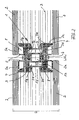
- Fig. 2 shows a practical embodiment of the stator assembly according to Fig. 1, wherein the H-profile of the stator 1 is designed as a hollow profile with hollow, transverse to the partition wall structure lying legs 1g and a hollow, approximately square crosspiece 1h.
- the four outer corners projecting strips 1a of Fig. 1 are formed on adapter elements 3, which have an approximately T-shaped cross-section and on the H-profile 1 preferably by a Locking connection are clipped.
- This locking connection is formed by a web 3c, which projects laterally on the adapter elements and in a groove 1 f in the end faces of the transverse to the partition wall structure leg 1g of the H-profile 1 engages.
- the on the adapter element 3 trained, outwardly projecting bar 3a has a groove 3d, in which a Sealing strip 4 is inserted, against which the glass plate 2.
- This sealing strip 4 is preferably attached to the glass plate 2 by gluing or self-adhesive, while the sealing strip 4 in the groove 3d of the adapter element 3 slidably or telescopically is guided, so that in a deflection movement of the glass plate 2 relative to the upright profile 1 the Sealing strip 4 adheres to the glass plate 2 and in the groove 3d of the adapter element 3 or in the protruding strip 3a moves.
- the sealing strip 4 is preferably made of silicone and contributes to the sound insulation.
- FIG. 2 shows fastening elements 5 attached to a position of the circumference of the glass plate 2, FIG. formed in the embodiment of FIG. 2 as a cross-sectionally approximately Z-shaped bracket are, with a leg 5a glued to the inside of the glass plate 2 and with the opposite leg 5b are attached to the H-profile 1, in this embodiment by a screw 6 passing through the two legs 5b and a damping element 7 out and screwed into the hollow crosspiece 1h of the H-shaped stand profile 1 is.
- the glass plate 2 to the fasteners 5 instead of a bond fastened by a screw, wherein through a hole in the glass pane. 2 a screw, not shown, inserted into the leg 5a of the fastener 5 becomes.
- the distance of the edges 2a of the glass sheets 2 in the region of a stud profile 1 corresponds Preferably, the incision or the recess 1e (Fig. 1) of the H-profile 1 and he is expediently at least 3 mm, in the illustrated embodiment about 10 mm.
- FIG. 3 shows a section through an H-shaped upright profile 1, compared to that in FIG. 2 is slightly modified, so that the hollow crosspiece 1h of the H-profile is wider and thereby the Groove between the two legs of the H fails. 3 shows the upright profile 1 outside the area of the fastening elements 5.
- the attachment of power adapter elements 3 on the upright profile 1 brings the Advantage with itself that, for example, with a connection of z.
- the upright profile 1 is designed as an adapter profile, depending on from the wall elements to be mounted (glass plate or shuttering board) with a corresponding Provided adapter element 3 and thus adapted to different requirements can be.
- Fig. 4 shows a modified embodiment, wherein the fastening elements for the Glass plates 2 as L-profiles 5 'are formed, in which in the plane of the glass plates. 2 lying leg 5'a rests on the outside of the glass plate 2.
- 5c in Fig. 4 is a Interposed between the fastener and the glass plate, the one-sided may be self-adhesive to adhere to the fastener made of stainless steel. This intermediate seal 5c prevents contact between steel and glass.
- Between the legs 5'b is a cover 9 inserted, which connects to the stand profile 1 covers. In this Au Eliariaspiel the glass plate 2 - as Fig.
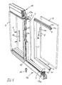
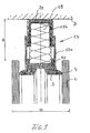
- Fig. 5 shows in perspective the structure of a glass partition according to FIG. 2, wherein the Leg 5b of the fasteners 5 in the side view in Fig. 5 cut out L-shaped are, so that the voltage applied to the H-shaped stand profile 1 leg 5b together connect.
- each side Tab 10 is provided, which is connected by the screws 6 with the H-shaped upright profile 1 becomes.
- clamping elements 11 are provided, in which the Tab 10 is screwed and which are connected to the upright profile 1, wherein the Fastener 5 is clamped to the upright profile 1.
- the upright profile 1 is blunt on a bottom profile 12 and a cover profile 13, these profiles 12 and 13 formed by U-shaped and telescopic nested elements are formed in a conventional manner.
- At 14 is in Fig. 5 denotes an adjusting screw, with which the two elements of the bottom profile 12 in the height can be adjusted.
- the adapter elements 3 are strip-shaped and at the corners Cut miter.
- the circumferential sealing strip 4 on the frame is in Fig. 5 only to the reproduced opposite lower adapter elements 3.
- About the bridge 3c is the Adapter element 3 clipped into a groove 1 f of the U-shaped element 12 a of the Bodenprofils12 are.
- a corresponding groove 1f is on the U-shaped element 13a of the ceiling profile 13 trained.
- FIG. 15 another adapter element is shown in Figs. 5 and 10, in the joint between the vertical edges 2a of the glass plates 2 in the free at this point groove 1f of Bottom profiles 12 used and bolted to the upright profile 1 by a screw 15b is.
- This adapter element 15 forms a projection attached to the upright profile 1 Connection with the soil profile.
- Such adapter elements 15 are also in the connection area used on the ceiling profile 13 between the glass plates 2.
- the stand profile 1 opposing adapter elements 15 form forks at the top and bottom End of the stud profile 1, which overlap the bottom profile 12 and the ceiling profile 13 laterally and thus set the stand 1 on the ceiling profile and the soil profile.
- the Adapter element 15 itself engages between the two legs of the cross-sectionally H-shaped Stand profile 1, wherein the connecting screw 15b screwed into the crosspiece of the H-profile becomes.
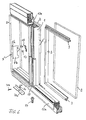
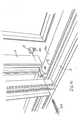
- Fig. 6 shows a perspective view of a structure, wherein the cross-sectionally L-shaped Fastening elements 5 'are connected by a plug connection with the upright profile 1.
- the fasteners 5 'with the shorter Leg 5'a be connected by gluing or screwing with the glass plate 2 and they are hung over the longer leg 5'b through a recess 5c on the bracket 16, which is screwed to the upright profile 1 by means of the screw 17.
- a screw connection or bonding the glass plate with the leg 5'a this can only at the Outside of a glass plate 2 abut, as shown in FIG. 4.
- the glass plate 2 on the fastening elements 5 'on Stand profile 1 is mounted, is preferably a support at the lower end of Glass plates 2 provided in such a way that the stand profile 1 a Abstützbügel 30 with a horizontal leg 30a is screwed by means of a screw 30b, wherein support the glass plates 2 on the leg 30a.
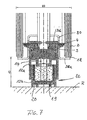
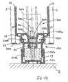
- Fig. 7 shows a cross section through a Floor profile 12 with Abst Reifenbügel 30 (FIG. 6) and horizontally protruding leg 30a, on where the glass plates 2 rest. By resting the glass plates 2 on the legs 30 a the fasteners 5 'are relieved.
- a silicone strip 18 is between Edge of the glass plate 2 and the leg 30a provided for sound insulation.
- the bottom profile 12 lies with a U-shaped element 12b on the unfinished floor R, wherein between the elements 12a and 12b, the adjusting screw 14 is inserted is to allow height adjustment.
- the lower element 12b is Schalldämmmaterial 19 preferably used in a U-shaped rail 20 whose mass for Sound insulation contributes.
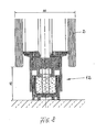
- Fig. 8 shows in section the structure of FIG. 7 outside of the adapter elements 15. As shown in Fig. 8, the attachment of the glass plates 2 also acts in Area of the ground profile 12 light and floating.
- Fig. 9 shows in section the reproduced in Fig. 5 ceiling profile 13, wherein on the U-profile 13a, the adapter elements 3 with the webs 3c inserted into corresponding grooves by snap fit are.
- a in the U-profile 13 a telescopically displaceable U-profile 13 b is located on the Cover D, wherein between the two U-profiles 13a and 13b sound insulation material 19 preferably is inserted in a U-rail 20.
- the stand profile 1 also of other elements than the adapter elements 3 and the H-shaped Basic profile 1 be composed, for example by two approximately U-shaped elements with a dividing line transverse to the plane of the dividing wall, the two elements being separated by a Locking connection or by a screw connection can be connected to each other and the ends of the legs of the U have outwardly projecting strips that the strips 1a in Fig. 1 and 3a in Fig. 2 correspond.
- Such a two-part design of the upright profile shows the embodiment of FIGS. 12 and 13.
- the recesses 1 c in Fig. 1 corresponding wells can also be concave or through an undercut may be formed on the upright profile.
- a flex seal 50 as shown in FIG. 11 shows, in the groove of the adapter elements 3 or a bar 1a (Fig. 1) via a projection 50a be used.
- Such a flex seal 50 with a bellows-shaped hollow cross-section 50b may be glued to the glass sheet 2 or even without adhesion just rest.
- Fig. 12 shows a cross section through a design of a stator profile 1, consisting of two profile elements 101 and 102 is composed.
- the outer outline of the composite Stand profiles 1 essentially correspond to those of the previously described St Sprofile according to Fig. 1 and Fig. 3.
- Fig. 13 shows the two profile elements only in cross section in the separated state.
- the profile element 101 has a transverse to the partition wall construction center web 101h, At the two ends of a hollow profile section 101i is formed, which with an oblique Wall section 101 d, the inclined recess provided with lateral recess 1c (s. Fig. 1).
- the outer side wall of the hollow profile section 101i is connected to the one leg of a U-section 101 a extends, which forms the bar 1 a in Fig. 1, wherein in the outward open U-section a flex seal 50 is inserted, as shown in FIG. 11.
- a bulge 101k is formed on the hollow profile section 101i, the one catch for a hook-shaped free leg end 102k of a Leg 1021 which protrudes on the profile element 102 and engages in the U-shaped area, the through the two hollow profile sections 101i and the central web 101h on the profile element 101 is formed.
- the profile element 102 has an approximately rectangular hollow cross-section 102h as a central web, Hollow profile sections 102i are integrally formed on both sides thereof. At the outer corners These hollow profile sections are like the profile element 101 by the legs 102a and 102b Molded moldings on which the glass plate 2 rests with the interposition of the flex seal 50.
- On the inside of the hollow profile section 102i is a transverse to the partition wall construction Groove 102e formed, which for receiving a later-explained connecting element 400 serves.
- the transition between the outer leg of this groove 102 e and the for the Locking connection provided leg 1021 is slightly weakened at 102f in cross section formed so that the leg 1021 can spring back easier to engage and disengage.
- the opposite inner sides of the hollow profile sections 101i and 102i limit the in Fig. 1 with 1e designated U-shaped recess having a groove along the upright profile for Insertion of the fastening elements 5 forms.
- the groove bottom is in this embodiment formed by the legs 1021 of the profile element 102.
- Fig. 12 are on the opposite sides of the partition wall structure different fasteners used in the upright profile.
- L-shaped fastening elements 5 ' are used, which abut with the outer leg 5'a on the outside of the glass plate 2, such as this Fig. 4 shows, wherein like components are provided with the same reference numerals.
- Fig. 12 On the upper side in Fig. 12 are - similar to the embodiment in Fig. 2 - angled Fastening elements 5 inserted into the groove 1e of the stator profile, the outer leg 5a are surrounded by a sealing material 5d inserted into a U-shaped element 5e is, whose outer leg is glued to the inside of the glass plate 2, for example.
- the glass plate 2 is fixed to the attached to the upright profile 1, rigid Fixing element 5 elastically mounted.
- the structure around the leg 5a of the fastener with the sealing material 5d and the U-shaped fastener 5e is formed so as to be in the clearance F be accommodated between the two strips 101a and 102a of the two profile elements can.
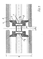
- FIG. 14 shows, in accordance with the view in FIG. 7, a bottom profile 120 which, in the view according to FIG Fig. 12 is formed continuously, that extends over the cross section of the stator profile 1.
- the two downwardly projecting legs 120a telescopically engage in the U-shaped Element 12b, which rests on the unfinished floor R.
- hollow chambers 120i are integrally formed in the bottom profile 120 of FIG., At the top outer edges strips 120a are formed for receiving the flex seal 50, as this also on the profile element 102 in Fig. 12 is the case.
- Between the two hollow chambers 120i is a hollow central web 120 h formed under the formed in a molded groove, the adjusting screw 14 is inserted, which extends through the sound absorbing material 19 and the element 12b is present.
- the adjusting screw 14 is through an extension portion 14 a through the bottom profile 120 and the legs 400 a of the connecting element 400, so that the adjusting screw 14 in Fig. 12 and 14 is accessible from above and can be rotated.
- L-shaped Abstweilbügel 300 are provided by means of Bolts 300b are mounted in the region of the hollow chambers 120i and with the approximately horizontal outwardly projecting legs 300a carry the glass plate 2, preferably with an intermediate layer a silicone strip 18.
- Fig. 12 shows a top view of this Abstweilbügel 300th
- the Abstützbügel 300 preferably engages with the voltage applied to the bottom profile 120 leg in a groove 120k formed on the underside of the strip 120a forming leg is and serves to fix and support the AbstNeillbügels 300.
- the widened leg 400b of the L-shaped connecting element 400 whose narrower leg 400a engages in the groove 120c of the bottom profile 12, the obliquely has outwardly inclined flanks such as the profile elements 101 and 102 of the stator profile.
- the widened portion 400b, in the lateral Grooves 102e of the profile element 102 engages, for example by means of blind rivets 400c attached to the profile element 102, and with 400d is a screw designated by means of the Connecting element 400 is connected via the leg 400a with the bottom profile 120.
- a connecting element 400 with the leg 400b inserted into the profile element 102 and fixed by means of the blind rivets 400c, whereupon the connecting element 400 on the bottom profile 120, for example by means of the blind rivet 400d can be positioned and fastened. This can be done via the extension section 14a of the adjusting screw 14, the height adjustment be made before the Profile element 101 mounted on the preassembled profile element 102 through the latching connection becomes.
- Fig. 15 shows, as shown in Fig. 9, a ceiling profile 130 spaced at two Legs 130a telescopically engages in a U-shaped rail 13b, which at the Cover D is present and attached to this.
- the ceiling profile 130 overall formed approximately U-shaped, wherein corresponding to the hollow chambers 120i formed on the bottom profile hollow profile sections 130i, where the strips 130a are formed, in which the glass plate 2 is applied,
- Fig. 15 shows by dashed lines Connecting element 400, as in the construction of FIG. 14 between ceiling profile 130th and profile element 102 is inserted.
- the ceiling profile 130 has as the bottom profile 120 in the central region a groove 130c, in which the narrow leg 400a of the corner connector intervenes.
Landscapes
- Engineering & Computer Science (AREA)
- Civil Engineering (AREA)
- Structural Engineering (AREA)
- Joining Of Corner Units Of Frames Or Wings (AREA)
- Securing Of Glass Panes Or The Like (AREA)
Applications Claiming Priority (4)
| Application Number | Priority Date | Filing Date | Title |
|---|---|---|---|
| DE202004007841U | 2004-05-14 | ||
| DE200420007841 DE202004007841U1 (de) | 2004-05-14 | 2004-05-14 | Aufbau für eine Glastrennwand |
| CH20942004 | 2004-12-17 | ||
| CH20942004A CH695277A5 (de) | 2004-05-14 | 2004-12-17 | Aufbau einer Glastrennwand. |
Publications (2)
| Publication Number | Publication Date |
|---|---|
| EP1596019A2 true EP1596019A2 (fr) | 2005-11-16 |
| EP1596019A3 EP1596019A3 (fr) | 2008-01-23 |
Family
ID=34936278
Family Applications (1)
| Application Number | Title | Priority Date | Filing Date |
|---|---|---|---|
| EP05010029A Withdrawn EP1596019A3 (fr) | 2004-05-14 | 2005-05-09 | Assemblage de cloison vitrée |
Country Status (1)
| Country | Link |
|---|---|
| EP (1) | EP1596019A3 (fr) |
Cited By (4)
| Publication number | Priority date | Publication date | Assignee | Title |
|---|---|---|---|---|
| EP1854955A2 (fr) * | 2006-05-12 | 2007-11-14 | Bene AG | Paroi de séparation comprenant un élément en verre sans cadre |
| EP1854932A2 (fr) * | 2006-05-12 | 2007-11-14 | Bene AG | Dispositif de mise à niveau |
| ES2366515A1 (es) * | 2009-11-10 | 2011-10-21 | Artis, Arquitectura Interior,S.A. | Sistema de nivelación para mampara. |
| CN114215295A (zh) * | 2021-12-21 | 2022-03-22 | 深圳市中装建设集团股份有限公司 | 一种装配式硅藻泥墙板结构系统 |
Citations (3)
| Publication number | Priority date | Publication date | Assignee | Title |
|---|---|---|---|---|
| GB537249A (en) * | 1940-04-01 | 1941-06-13 | Mellowes & Company Ltd | Improvements in or relating to metal frames for windows, panels or the like |
| FR2546209A1 (fr) * | 1983-05-17 | 1984-11-23 | Pjb Cloisons Amovibles | Profile pour la construction de cloisons, procede d'utilisation de celui-ci et cloisons obtenues par sa mise en oeuvre |
| EP0600545A1 (fr) * | 1992-12-01 | 1994-06-08 | HYDRO ALUMINIUM SYSTEMS S.p.A. | Ensemble de profilés métalliques pour cloison amovible et cloison amovible correpondante |
-
2005
- 2005-05-09 EP EP05010029A patent/EP1596019A3/fr not_active Withdrawn
Patent Citations (3)
| Publication number | Priority date | Publication date | Assignee | Title |
|---|---|---|---|---|
| GB537249A (en) * | 1940-04-01 | 1941-06-13 | Mellowes & Company Ltd | Improvements in or relating to metal frames for windows, panels or the like |
| FR2546209A1 (fr) * | 1983-05-17 | 1984-11-23 | Pjb Cloisons Amovibles | Profile pour la construction de cloisons, procede d'utilisation de celui-ci et cloisons obtenues par sa mise en oeuvre |
| EP0600545A1 (fr) * | 1992-12-01 | 1994-06-08 | HYDRO ALUMINIUM SYSTEMS S.p.A. | Ensemble de profilés métalliques pour cloison amovible et cloison amovible correpondante |
Cited By (8)
| Publication number | Priority date | Publication date | Assignee | Title |
|---|---|---|---|---|
| EP1854955A2 (fr) * | 2006-05-12 | 2007-11-14 | Bene AG | Paroi de séparation comprenant un élément en verre sans cadre |
| EP1854932A2 (fr) * | 2006-05-12 | 2007-11-14 | Bene AG | Dispositif de mise à niveau |
| EP1854955A3 (fr) * | 2006-05-12 | 2008-06-04 | Bene AG | Paroi de séparation comprenant un élément en verre sans cadre |
| EP1854932A3 (fr) * | 2006-05-12 | 2008-06-25 | Bene AG | Dispositif de mise à niveau |
| AT503532B1 (de) * | 2006-05-12 | 2013-11-15 | Bene Ag | Trennwand |
| AT503531B1 (de) * | 2006-05-12 | 2013-11-15 | Bene Ag | Nivellierungsvorrichtung |
| ES2366515A1 (es) * | 2009-11-10 | 2011-10-21 | Artis, Arquitectura Interior,S.A. | Sistema de nivelación para mampara. |
| CN114215295A (zh) * | 2021-12-21 | 2022-03-22 | 深圳市中装建设集团股份有限公司 | 一种装配式硅藻泥墙板结构系统 |
Also Published As
| Publication number | Publication date |
|---|---|
| EP1596019A3 (fr) | 2008-01-23 |
Similar Documents
| Publication | Publication Date | Title |
|---|---|---|
| DE4030117C2 (de) | Abgehängte Kassettendecke | |
| EP0440104B1 (fr) | Mur de séparation pour la subdivision d'espaces | |
| EP0206146A2 (fr) | Sous-structure pour revêtements de bâtiments | |
| DE4226742A1 (de) | Verkleidungselement für Böden, Decken, Wände und Fassaden | |
| EP0180837B1 (fr) | Jeu de pièces séparées pour un dispositif de fixation de murs rideaux | |
| EP0921253B1 (fr) | Système de montage pour panneaux de revêtement de façade de bâtiments | |
| EP1596019A2 (fr) | Assemblage de cloison vitrée | |
| DE3213717A1 (de) | Flaechenelement zur bildung flaechiger gegenstaende, wie sichtblenden, und zum zusammensetzen von wand- und deckenteilen fuer messestaende oder dergleichen aufbauten | |
| CH695277A5 (de) | Aufbau einer Glastrennwand. | |
| EP0364768B1 (fr) | Elément de cloison de séparation | |
| AT401788B (de) | Fassade | |
| AT395332B (de) | Tragkonstruktion, insbesondere fuer glasdaecher | |
| AT405200B (de) | Vorgesetzte wandverkleidungen, verfahren zu deren herstellung und montageprofil hiefür | |
| EP1277910B1 (fr) | Joint descendant pour une porte sans seuil | |
| EP0722033B1 (fr) | Montant d'angle pour façade composée d'éléments avec un encadrement en matière plastique | |
| AT524994B1 (de) | Bausatz für ein Gerätehaus | |
| EP1277895A2 (fr) | Elément de fixation pour la fixation présuspendue de plaques de façade à un mur | |
| EP3257413A1 (fr) | Partie fonctionnelle et/ou décorative à insérer dans une zone cornière ou dans une niche, par exemple d'au moins un espace en partie carrelé | |
| DE3809020C2 (fr) | ||
| DE2250987A1 (de) | Nutwand fuer verkaufsraeume | |
| DE19514220A1 (de) | Tragschienensystem mit verstellbarer Halterung | |
| DE3546145A1 (de) | Vorhangfassadenkonstruktion | |
| DE2320592A1 (de) | Wandsystem, insbesondere fuer einbauwaende | |
| DE8519434U1 (de) | Wandelement für einen Bausatz zur Auskleidung und Aufteilung eines Raumes | |
| EP1589158A2 (fr) | Dispositif de fixation d'éléments de façade |
Legal Events
| Date | Code | Title | Description |
|---|---|---|---|
| PUAI | Public reference made under article 153(3) epc to a published international application that has entered the european phase |
Free format text: ORIGINAL CODE: 0009012 |
|
| AK | Designated contracting states |
Kind code of ref document: A2 Designated state(s): AT BE BG CH CY CZ DE DK EE ES FI FR GB GR HU IE IS IT LI LT LU MC NL PL PT RO SE SI SK TR |
|
| AX | Request for extension of the european patent |
Extension state: AL BA HR LV MK YU |
|
| PUAL | Search report despatched |
Free format text: ORIGINAL CODE: 0009013 |
|
| AK | Designated contracting states |
Kind code of ref document: A3 Designated state(s): AT BE BG CH CY CZ DE DK EE ES FI FR GB GR HU IE IS IT LI LT LU MC NL PL PT RO SE SI SK TR |
|
| AX | Request for extension of the european patent |
Extension state: AL BA HR LV MK YU |
|
| STAA | Information on the status of an ep patent application or granted ep patent |
Free format text: STATUS: THE APPLICATION IS DEEMED TO BE WITHDRAWN |
|
| 18D | Application deemed to be withdrawn |
Effective date: 20071201 |