EP1595634B1 - Elektrische Lichtbogenvorrichtung mit einem gesteuerten Wellenformprofil für Kernelektroden - Google Patents
Elektrische Lichtbogenvorrichtung mit einem gesteuerten Wellenformprofil für Kernelektroden Download PDFInfo
- Publication number
- EP1595634B1 EP1595634B1 EP20050008352 EP05008352A EP1595634B1 EP 1595634 B1 EP1595634 B1 EP 1595634B1 EP 20050008352 EP20050008352 EP 20050008352 EP 05008352 A EP05008352 A EP 05008352A EP 1595634 B1 EP1595634 B1 EP 1595634B1
- Authority
- EP
- European Patent Office
- Prior art keywords
- waveform
- profile
- electrode
- welding
- waveforms
- Prior art date
- Legal status (The legal status is an assumption and is not a legal conclusion. Google has not performed a legal analysis and makes no representation as to the accuracy of the status listed.)
- Expired - Lifetime
Links
- 238000010891 electric arc Methods 0.000 title claims abstract description 36
- 238000003466 welding Methods 0.000 claims abstract description 213
- 238000000034 method Methods 0.000 claims abstract description 117
- 230000008569 process Effects 0.000 claims abstract description 79
- 230000004907 flux Effects 0.000 claims description 8
- 238000003860 storage Methods 0.000 claims description 8
- 238000002844 melting Methods 0.000 claims description 6
- 230000008018 melting Effects 0.000 claims description 6
- 238000005275 alloying Methods 0.000 claims description 5
- 230000002829 reductive effect Effects 0.000 claims description 4
- 238000010438 heat treatment Methods 0.000 claims description 3
- 239000000654 additive Substances 0.000 claims 1
- 239000002184 metal Substances 0.000 description 32
- 239000011162 core material Substances 0.000 description 31
- 238000005516 engineering process Methods 0.000 description 28
- 230000008901 benefit Effects 0.000 description 18
- 210000004027 cell Anatomy 0.000 description 17
- 239000007789 gas Substances 0.000 description 13
- 239000000470 constituent Substances 0.000 description 8
- 230000001276 controlling effect Effects 0.000 description 8
- 230000008021 deposition Effects 0.000 description 8
- 230000002441 reversible effect Effects 0.000 description 8
- 230000001360 synchronised effect Effects 0.000 description 8
- 230000007704 transition Effects 0.000 description 8
- 238000011109 contamination Methods 0.000 description 7
- 238000010586 diagram Methods 0.000 description 7
- 230000035515 penetration Effects 0.000 description 7
- 230000000694 effects Effects 0.000 description 6
- 230000005355 Hall effect Effects 0.000 description 5
- 230000002596 correlated effect Effects 0.000 description 5
- 230000006872 improvement Effects 0.000 description 5
- 230000007774 longterm Effects 0.000 description 5
- 239000007787 solid Substances 0.000 description 5
- 240000007320 Pinus strobus Species 0.000 description 4
- 230000008859 change Effects 0.000 description 4
- 238000010276 construction Methods 0.000 description 4
- 230000000875 corresponding effect Effects 0.000 description 4
- 239000000155 melt Substances 0.000 description 4
- 239000003973 paint Substances 0.000 description 4
- 230000003247 decreasing effect Effects 0.000 description 3
- 239000004615 ingredient Substances 0.000 description 3
- 239000000203 mixture Substances 0.000 description 3
- 230000004048 modification Effects 0.000 description 3
- 238000012986 modification Methods 0.000 description 3
- 239000002245 particle Substances 0.000 description 3
- 206010001513 AIDS related complex Diseases 0.000 description 2
- 210000002945 adventitial reticular cell Anatomy 0.000 description 2
- 239000000956 alloy Substances 0.000 description 2
- 239000010953 base metal Substances 0.000 description 2
- 239000011324 bead Substances 0.000 description 2
- 230000007423 decrease Effects 0.000 description 2
- 230000003111 delayed effect Effects 0.000 description 2
- 238000011161 development Methods 0.000 description 2
- 230000000670 limiting effect Effects 0.000 description 2
- 238000004519 manufacturing process Methods 0.000 description 2
- 230000001681 protective effect Effects 0.000 description 2
- 230000004044 response Effects 0.000 description 2
- 239000002893 slag Substances 0.000 description 2
- 101100537937 Caenorhabditis elegans arc-1 gene Proteins 0.000 description 1
- UFHFLCQGNIYNRP-UHFFFAOYSA-N Hydrogen Chemical compound [H][H] UFHFLCQGNIYNRP-UHFFFAOYSA-N 0.000 description 1
- 230000009471 action Effects 0.000 description 1
- 230000003213 activating effect Effects 0.000 description 1
- 229910045601 alloy Inorganic materials 0.000 description 1
- 230000009286 beneficial effect Effects 0.000 description 1
- 230000015572 biosynthetic process Effects 0.000 description 1
- 238000006243 chemical reaction Methods 0.000 description 1
- 239000000356 contaminant Substances 0.000 description 1
- 238000001514 detection method Methods 0.000 description 1
- 238000011156 evaluation Methods 0.000 description 1
- 230000006870 function Effects 0.000 description 1
- 229910052739 hydrogen Inorganic materials 0.000 description 1
- 239000001257 hydrogen Substances 0.000 description 1
- 230000000977 initiatory effect Effects 0.000 description 1
- 230000003993 interaction Effects 0.000 description 1
- 239000000463 material Substances 0.000 description 1
- 239000007769 metal material Substances 0.000 description 1
- 239000012768 molten material Substances 0.000 description 1
- 230000009467 reduction Effects 0.000 description 1
- 230000008439 repair process Effects 0.000 description 1
- 230000001846 repelling effect Effects 0.000 description 1
- 230000000717 retained effect Effects 0.000 description 1
- 238000007493 shaping process Methods 0.000 description 1
- 238000004904 shortening Methods 0.000 description 1
- 230000002195 synergetic effect Effects 0.000 description 1
- 230000002194 synthesizing effect Effects 0.000 description 1
Images


Classifications
-
- B—PERFORMING OPERATIONS; TRANSPORTING
- B23—MACHINE TOOLS; METAL-WORKING NOT OTHERWISE PROVIDED FOR
- B23K—SOLDERING OR UNSOLDERING; WELDING; CLADDING OR PLATING BY SOLDERING OR WELDING; CUTTING BY APPLYING HEAT LOCALLY, e.g. FLAME CUTTING; WORKING BY LASER BEAM
- B23K9/00—Arc welding or cutting
- B23K9/09—Arrangements or circuits for arc welding with pulsed current or voltage
- B23K9/091—Arrangements or circuits for arc welding with pulsed current or voltage characterised by the circuits
- B23K9/092—Arrangements or circuits for arc welding with pulsed current or voltage characterised by the circuits characterised by the shape of the pulses produced
-
- B—PERFORMING OPERATIONS; TRANSPORTING
- B23—MACHINE TOOLS; METAL-WORKING NOT OTHERWISE PROVIDED FOR
- B23K—SOLDERING OR UNSOLDERING; WELDING; CLADDING OR PLATING BY SOLDERING OR WELDING; CUTTING BY APPLYING HEAT LOCALLY, e.g. FLAME CUTTING; WORKING BY LASER BEAM
- B23K9/00—Arc welding or cutting
- B23K9/09—Arrangements or circuits for arc welding with pulsed current or voltage
-
- B—PERFORMING OPERATIONS; TRANSPORTING
- B23—MACHINE TOOLS; METAL-WORKING NOT OTHERWISE PROVIDED FOR
- B23K—SOLDERING OR UNSOLDERING; WELDING; CLADDING OR PLATING BY SOLDERING OR WELDING; CUTTING BY APPLYING HEAT LOCALLY, e.g. FLAME CUTTING; WORKING BY LASER BEAM
- B23K9/00—Arc welding or cutting
- B23K9/10—Other electric circuits therefor; Protective circuits; Remote controls
- B23K9/1006—Power supply
- B23K9/1043—Power supply characterised by the electric circuit
- B23K9/1068—Electric circuits for the supply of power to two or more arcs from a single source
Definitions
- the present invention relates to the art of electric arc welding and more particularly to an electric arc welder with waveform profile control for cored electrodes used in pipeline welding, primarily off-shore pipeline welding, and to a corresponding method of welding as disclosed in US-B-6 717 107 .
- the present invention is directed to an electric arc welder system utilizing high capacity alternating circuit power sources for driving two or more tandem electrodes of the type used in seam welding of large metal blanks, such as pipelines.
- the power sources use the switching concept disclosed in Stava 6,111,216 wherein the power supply is an inverter having two large output polarity switches with the arc current being reduced before the switches reverse the polarity. Consequently, the term "switching point" is a complex procedure whereby the power source is first turned off awaiting a current less than a preselected value, such as 100 amperes. Upon reaching the 100 ampere threshold, the output switches of the power supply are reversed to reverse the polarity from the D.C. output link of the inverter.
- the "switching point" is an off output command, known as a "kill” command, to the power supply inverter followed by a switching command to reverse the output polarity.
- the kill output can be a drop to a decreased current level.
- This procedure is duplicated at each successive polarity reversal so the AC power source reverses polarity only at a low current.
- snubbing circuits for the output polarity controlling switches are reduced in size or eliminated. Since this switching concept is preferred to define the switching points as used in the present invention, Stava 6,111,216 is referred to for details.
- the concept of an AC current for tandem electrodes is well known in the art. Patent No.
- 6,291,798 and 6,207,929 disclose further arc welding systems wherein each electrode in a tandem welding operation is driven by two or more independent power supplies connected in parallel with a single electrode arc.
- the system involves a single set of switches having two or more accurately balanced power supplies forming the input to the polarity reversing switch network operated in accordance with Stava 6,111,216.
- Each of the power supplies is driven by a single command signal and, therefore, shares the identical current value combined and directed through the polarity reversing switches.
- This type system requires large polarity reversing switches since all of the current to the electrode is passed through a single set of switches.
- the present invention relates to coordination of a specific waveform profile for an AC waveform, which profile is coordinated with a particular cored electrode used in welding, such as pipeline welding.
- a particular cored electrode used in welding normally uses DC positive or DC negative, especially when using a cored electrode.
- a cored electrode has been tried.
- a cored electrode has been suggested for use in conjunction with a STT waveform which waveform can be positive or negative.
- STT positive and a STT negative This concept is not AC, but is shown in Stava 6,051,810, which is referred to herein as background information.
- the timing cannot be accurately controlled.
- the switch timing for a given electrode need only be shifted on a time basis, but need not be accurately identified for a specific time.
- the described system requiring balancing the current and a single switch network has been the manner of obtaining high capacity current for use in tandem arc welding operations when using an ethernet network or an internet and ethernet control system.
- Such systems could be controlled by a network; however, the parameter to each paralleled power supply could not be varied.
- Each of the cells could only be offset from each other by a synchronizing signal.
- Such systems were not suitable for central control by the internet and/or local area network control because an elaborate network to merely provide offset between cells was not advantageous.
- Houston 6,472,634 discloses the concept of a single AC arc welding cell for each electrode wherein the cell itself includes one or more paralleled power supplies each of which has its own switching network. The output of the switching network is then combined to drive the electrode. This allows the use of relatively small switches for polarity reversing of the individual power supplies paralleled in the system.
- relatively small power supplies can be paralleled to build a high current input to each of several electrodes used in a tandem welding operation.
- the use of several independently controlled power supplies paralleled after the polarity switch network for driving a single electrode allows advantageous use of a network, such as the internet or ethernet.
- the switch point is a "kill" command awaiting detection of a current drop below a minimum threshold, such as 100 amperes.
- a minimum threshold such as 100 amperes.
- the switch points between parallel power supplies are coordinated accurately by an interface card having an accuracy of less than 10 ⁇ s and preferably in the range of 1-5 ⁇ s. This timing accuracy coordinates and matches the switching operation in the paralleled power supplies to coordinate the AC output current.
- the set of weld parameters for each power supply is available on a less accurate information network, to which the controllers for the paralleled power supplies are interconnected with a high accuracy digital interface card.
- the switching of the individual, paralleled power supplies of the system is coordinated.
- the information network includes synchronizing signals for initiating several arc welding systems connected to several electrodes in a tandem welding operation in a selected phase relationship.
- Each of the welding systems of an electrode has individual switch points accurately controlled while the systems are shifted or delayed to prevent magnetic interference between different electrodes. This allows driving of several AC electrodes using a common information network.
- the Houston 6,472,634 system is especially useful for paralleled power supplies to power a given electrode with AC current.
- the switch points are coordinated by an accurate interface and the weld parameter for each paralleled power supply is provided by the general information network.
- This background is technology developed and patented by assignee and does not necessarily constitute prior art just because it is herein used as "background.”
- the system comprises a first controller for a first power supply to cause the first power supply to create an AC current between the electrode and workpiece by generating a switch signal with polarity reversing switching points in general timed relationship with respect to a given system synchronizing signal received by the first controller.
- This first controller is operated at first welding parameters in response to a set of first power supply specific parameter signals directed to the first controller.
- the slave controller operates at second weld parameters in response to the second set of power supply specific parameter signals to the slave controller.
- An information network connected to the first controller and the second or slave controller contains digital first and second power supply specific parameter signals for the two controllers and the system specific synchronizing signal.
- the controllers receive the parameter signals and the synchronizing signal from the information network, which may be an ethernet network with or without an internet link, or merely a local area network.
- the invention involves a digital interface connecting the first controller and the slave controller to control the switching points of the second or slave power supply by the switch signal from the first or master controller.
- the first controller starts a current reversal at a switch point. This event is transmitted at high accuracy to the slave controller to start its current reversal process.
- each controller senses an arc current less than a given number, a "ready signal" is created. After a "ready” signal from all paralleled power supplies, all power supplies reverse polarity. This occurs upon receipt of a strobe or look command each 25 ⁇ s. Thus, the switching is in unison and has a delay of less than 25 ⁇ s. Consequently, both of the controllers have interconnected data controlling the switching points of the AC current to the single electrode.
- the same controllers receive parameter information and a synchronizing signal from an information network which in practice comprises a combination of internet and ethernet or a local area ethernet network.
- the timing accuracy of the digital interface is less than about 10 ⁇ s and, preferably, in the general range of 1-5 ⁇ s.
- the switching points for the two controllers driving a single electrode are commanded within less than 5 ⁇ s. Then, switching actually occurs within 25 ⁇ s. At the same time, relatively less time sensitive information is received from the information network also connected to the two controllers driving the AC current to a single electrode in a tandem welding operation. The 25 ⁇ s maximum delay can be changed, but is less than the switch command accuracy.
- the unique control system disclosed in Houston 6,472,634 is used to control the power supply for tandem electrodes used primarily in pipe seam welding and disclosed in Stava 6,291,798.
- This Stava patent relates to a series of tandem electrodes movable along a welding path to lay successive welding beads in the space between the edges of a rolled pipe or the ends of two adjacent pipe sections.
- the individual AC waveforms used in this unique technology are created by a number of current pulses occurring at a frequency of at least 18 kHz with a magnitude of each current pulse controlled by a wave shaper. This technology dates back to Blankenship 5,278,390.
- the welding process When using the waveform technology as so far described for off-shore welding or welding on pipelines, the welding process generally used solid welding wires with a shielding gas.
- DC welding as described, together with STT welding has been the normal practice.
- cored electrodes When cored electrodes are used, the core can be formed of alloy material to make the weld metal.
- Such processes generally required DC.welding using cored electrodes. Consequently, in the past cored or solid wire using a DC process with external shielding gas has been the normal practice, especially for off-shore welding and pipeline welding.
- the DC welding presented little problems of uneven burn back of the sheath and core.
- the electrodes were cored for alloying. The need for controlled strength and hardness combined with low diffusible hydrogen limits made it difficult to use AC welding.
- US-B-6 717 107 shows an electric arc welder for creating a welding process in the form of a succession of waveforms between an electrode and a workpiece by a power source comprising a high frequency switching device for creating the individual waveforms in said succession of waveforms, each waveform having a profile, wherein said profile is determined by the input signal to a wave shaper.
- a select switch is provided to select said input signal from two sources, and said wave shaper causes said power source to create one of two specific waveform profiles according to the setting of the switch.
- US-B-6 717 107 also shows a method of welding with an electrode, comprising switching between two waveforms with a profile to select one waveform and to create a series of this waveform to provide a weld process, and welding with said electrode using said weld process.
- the present invention is used with a cored electrode having a special constructed AC waveform generated between the cored electrode and workpiece, which special AC waveform is outputted in succession to constitute the welding process.
- the waveform in the AC welding process is controlled in a unique manner that adjusts several profile parameters and also the energy profile of the individual sections of the waveform.
- the waveform is coordinated with a specific cored electrode so the sheath and core burn back at the proven rate. AC welding could not be used successfully for a cored electrode.
- the creation of a special profile for the waveform effects the overall welding process in a unique manner that accurately controls the process using waveform technology of the type pioneered by The Lincoln Electric Company of Cleveland, Ohio.
- the welding process is controlled to effect several characteristics, such as penetration into the base metal, the melt off rate of the electrode, the heat input into the base metal, and the welding travel speed as well as the wire feed speed while using AC welding with a cored electrode.
- the arc welding current and/or arc welding voltage waveform is generated to essentially "paint" a desired waveform for coordination with a given cored electrode to effect the mechanical and metallurgical properties of the "as welded" weld metal resulting from the welding process.
- the invention selects the profile of an AC waveform for a given electrode. By having the ability to accurately control the exact profile of the AC waveform, this invention is made possible.
- an electric arc welder for creating a succession of AC waveforms between a cored electrode and a workpiece by a power source comprising an high frequency switching device such as an inverter or its equivalent chopper for creating individual waveforms in the succession of waveforms constituting the welding process.
- an high frequency switching device such as an inverter or its equivalent chopper for creating individual waveforms in the succession of waveforms constituting the welding process.
- Each of the individual waveforms has a precise general profile determined by the magnitude of each of a large number of short current pulses generated at a frequency of at least 18 kHz by a pulse width modulator with the magnitude of the current pulses controlled by a wave shaper.
- the polarity of any portion of the individual AC waveform is determined by the data of a polarity signal.
- a profile control network is used for establishing the general profile of an individual waveform by setting more than one profile parameter of the individual waveform.
- the parameters are selected from the class consisting of frequency, duty cycle, up ramp rate and down ramp rate.
- a magnitude circuit for adjusting the individual waveform profile to set total current, voltage and/or power for the waveform without substantially changing the set general profile. This concept of the invention is normally accomplished in two sections where the energy is controlled in the positive polarity and in the negative polarity of the generated waveform profile.
- a method of electric arc welding by creating a succession of AC waveforms between a cored electrode and a workpiece by a power source comprising an high frequency switching device for creating individual waveforms in the succession of waveforms constituting the weld process.
- Each of the individual waveforms has profile determined by the magnitude of each of a large number of short current pulses generated at a frequency of at least 18 kHz by a pulse width modulator with the magnitude of the current pulses controlled by a wave shaper.
- the method comprises determining the plurality of any portion of the individual waveform by the data of a plurality signal, establishing the general profile of an individual waveform by setting more than one profile parameter of an individual waveform, said parameters selected from the class consisting of frequency, duty cycle, up ramp rate and down ramp rate and adjusting the waveform to set the total magnitude of current, voltage and/or power without substantially changing the set profile.
- the invention accomplishes AC welding with cored self shielding electrodes to achieve superior productivity and mechanical properties by lowering the heat input per unit of deposition and by shortening the arc length to reduce atmospheric contamination. This has not been accomplished before in pipeline welding.
- the invention allows the use of a welding operation involving AC waveforms in a manner that can accomplish a short arc length to prevent atmospheric contamination. Furthermore, by using a self shielding electrode, the atmospheric wind can not blow away the shielding gas as is experienced in FCAW-G welding.
- the invention is the development of a new welding system making possible the use of cored electrodes. This is accomplished with an AC arc welding power source. The benefits of both a cored electrode and AC welding are obtained.
- the AC power source in accordance with the invention, is capable of generating a wave shape of virtually any form and is not limited to simply an AC sine wave or square wave.
- the AC waveform has a specific profile that is coordinated with an exact cored electrode to optimize the waveform profile for the electrode being used in the welding process.
- the waveform has an unbalanced relationship so that the positive and negative polarity portions of the welding process heat and deposit molten metal in a different manner to optimize the AC welding process.
- the constituents of the core material of the electrode is selected to achieve optimum results for the weld metal, in terms of metallurgical and mechanical properties of the "as welded" material.
- the electrode core chemistry is modified to take advantage of the various AC waveforms produced by the AC arc welding power source by coordinating the waveforms with the chemistry of the core.
- This has never been accomplished before and allows the use of cored electrodes with self shielding capability in off-shore pipeline welding. Different polarity portions of the waveform produce different welding results for a given electrode in terms of heat input to the work, melt off rate of the electrode and the metallurgical and mechanical properties of the weld deposit.
- an AC welding power source as described, in conjunction with a tubular electrode of the self shielding type, superior welding results are achieved.
- the self shielded electrode does not require additional shielding gas and therefore results in additional savings in the welding process.
- the power source uses waveform technology where the profile of the waveform can be created.
- the profile can be selected based upon both the specific construction of the cored electrode and the wire feed speed of the welding process. Consequently, a distinct advantage of the invention is the ability to control the actual waveform of the AC welding process by the specific cored electrode used and the set point of the welder.
- the invention provides significant benefits in the quality of the weld and also increases welding speed. Consequently, the production rate using the present invention is increased.
- the invention furthermore benefits application in the field of cross country pipeline welding, as well as off-shore welding of pipelines or other structures.
- the weld quality and welding speed or production is of essence.
- cross country and off-shore pipeline construction projects it is well known that such projects normally include high hourly costs for the construction equipment. This is especially the case on off-shore pipeline projects, where the ships used for constructing the pipeline normally lease at a cost of millions of dollars per day. Consequently, the welding of the pipeline must be done as quickly as possible with a minimum of repairs to minimize the cost factor in the process. Consequently, the AC welding process and the tubular cored electrode significantly benefit the industry in terms of producing high quality welds at a faster speed.
- a broad aspect of the present invention is the tailoring or coordinating of accurately profiled waveforms of an AC welding process with the exact chemistry and composition of the electrode.
- a given electrode is identified to provide an identification signal.
- This signal is used to select the exact coordinated AC waveform from many waveforms stored in the power source.
- This concept of selecting the profile of the AC waveform to match a specific cored electrode has not been heretofore used. This process allows AC welding of a pipeline with a cored, self shielded electrode.
- an electric arc welder for creating a welding process in the form of a succession of AC waveforms between a particular type of cored electrode with a sheath and core and a workpiece by a power source.
- the power source comprises a high frequency switching device for creating the individual waveforms in the succession of waveforms constituting the welding process.
- Each waveform has a profile that is formed by the magnitude of the large number of short current pulses generated at a frequency of at least 18 kHz, where the profile is determined by the input signal to a wave shaper controlling the short current pulses.
- the invention involves a circuit to create a profile signal indicative of a particular type electrode and a select circuit to select the input signal based upon the profile signal indicative of a specific electrode.
- the wave shaper causes the power source to create a specific waveform profile for a particular type of cored electrode.
- a cored electrode is usable in an AC waveform welding process. This process was not generally obtainable in the past.
- a method of welding with a specific cored electrode having a sheath and core comprises using a waveform with a specific profile tailored for welding with a specific cored electrode, creating a series of these selected waveforms to provide a welding process and welding with the electrode using this selected welding process.
- the created waveform is an AC waveform.
- the waveform can have a different shape for the positive polarity and the negative polarity. In this manner, the one polarity involves a. relatively low current for a longer period of time. This maintains the arc length relatively short to reduce the amount of exposure to the atmosphere during the welding process.
- the waveform is an AC waveform so that the profile of the selected waveform of the method is accurately controlled.
- the primary object of the present invention is the provision of an electric arc welder, wherein the waveform is created by waveform technology and is developed for a particular cored electrode so that an off-shore pipeline welding process can be accomplished using FCAW-SS process.
- Another object of the present invention is the provision of a method, wherein waveform technology is used to generate waveforms coordinated with a particular cored electrode.
- Yet another object of the present invention is the provision of a welder and method, as defined above, which welder and method results in a relatively short arc length and is used in high wind conditions for off-shore pipeline welding and pipeline welding in general.
- Still a further object of the present invention is the provision of an electric arc welder and method, as defined above, wherein the AC waveform has a low heat polarity portion to obtain a short arc length.
- Still another object of the present invention is the provision of a welder and method, as defined above, which welder and method utilizes a cored electrode that can be operated DC positive, DC negative, but preferably AC.
- Another object of the present invention is the provision of an electric arc welder and method, as defined above, which welder and method can be used for AC open root welding and combines self shielding electrodes with an AC waveform that is tailored to the particular electrode.
- Still a further object of the present invention is the provision of an electric arc welder and method, as defined above, which welder and method utilizes both the identification of a particular electrode and the wire feed speed to select the desired tailored waveform.
- Another object of the present invention is the provision of an electric arc welder that has the capabilities of accurately controlling the profile of the waveform so the profile of the waveform can be coordinated with a given electrode, especially a cored electrode.
- Yet another object of the present invention is the provision of an electric arc welder and method, as defined above, which welder and method allow coordination between a self shielded electrode and a waveform of the programmable power source, either DC or AC. In this manner, a waveform is programmed into the power source so superior results are accomplished when using the corresponding, matched cored electrode.
- Still a further object of the present invention is the provision of an electric arc welder utilizing waveform technology, which welder is capable of having a waveform that is tailored made for a specific cored electrode. This is especially advantageous for a self shielded electrode when used in an AC welding process.
- Yet another object of the present invention is the provision of an electric arc welder and method, as defined above, which welder and method has a waveform coordinated with a self shielded electrode so that the sheath and core melts at substantially the same rate.
- Yet a further object of the present invention is the provision of an electric arc welder using waveform technology wherein the general profile of the individual waveforms constituting the AC welding process is accurately controlled to a given profile that will produce a weld with desired mechanical and metallurgical properties with a specific cored electrode.
- Another object of the present invention is the provision of an electric arc welder, as defined above, which electric arc welder generates a precise controllable and changeable general profile for the waveform of an AC welding process to thereby adjust the weld speed, deposition rate, heat input, mechanical and metallurgical properties and related characteristics to improve the quality and performance of the welding process.
- FIGURES 1 , 2 , 4 , 5 and 16 a background system for implementing the invention is shown in detail in FIGURES 1 , 2 , 4 , 5 and 16 .
- FIGURES 2 and 6-15 describe prior attributes of the disclosed background welding systems.
- the welder described in FIGURES 17 and 18 is used to construct the pRecise profile of the waveforms used in the wave shaper or waveform generator as a profile tailored for a specific electrode shown in FIGURE 20 .
- These electrode determined profiles are used in practicing the invention described by use of FIGURES 19-28 .
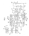
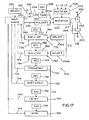
- FIGURE 1 discloses a single electric arc welding system S in the form of a single cell to create an alternating current as an arc at weld station WS.
- This system or cell includes a first master welder A with output leads 10, 12 in series with electrode E and workpiece W in the form of a pipe seam joint or other welding operation.
- Hall effect current transducer 14 provides a voltage in line 16 proportional to the current of welder A.
- Less time critical data, such as welding parameters, are generated at a remote central control 18.
- a slave following welder B includes leads 20, 22 connected in parallel with leads 10, 12 to direct an additional AC current to the weld station WS.
- Hall effect current transducer 24 creates a voltage in line 26 representing current levels in welder B during the welding operation. Even though a single slave or follower welder B is shown, any number of additional welders can be connected in parallel with master welder A to produce an alternating current across electrode E and workpiece W. The AC current is combined at the weld station instead of prior to a polarity switching network.
- Each welder includes a controller and inverter based power supply illustrated as a combined master controller and power supply 30 and a slave controller and power supply 32. Controllers 30, 32 receive parameter data and synchronization data from a relatively low level logic network. The parameter information or data is power supply specific whereby each of the power supplies is provided with the desired parameters such as current, voltage and/or wire feed speed.
- a low level digital network can provide the parameter information; however, the AC current for polarity reversal occurs at the same time.
- the "same" time indicates a time difference of less than 10 ⁇ s and preferably in the general range of 1-5 ⁇ s.
- the switching points and polarity information can not be provided from a general logic network wherein the timing is less precise.
- the individual AC power supplies are coordinated by high speed, highly accurate DC logic interface referred to as "gateways.” As shown in FIGURE 1 , power supplies 30, 32 are provided with the necessary operating parameters indicated by the bi-directional leads 42m, 42s, respectively. This non-time sensitive information is provided by a digital network shown in FIGURE 1 .
- Master power supply 30 receives a synchronizing signal as indicated by unidirectional line 40 to time the controllers operation of its AC output current.
- the polarity of the AC current for power supply 30 is outputted as indicated by line 46.
- the actual switching command for the AC current of master power supply 30 is outputted on line 44.
- the switch command tells power supply S, in the form of an inverter, to "kill,” which is a drastic reduction of current. In an alternative, this is actually a switch signal to reverse polarity.
- the "switching points" or command on line 44 preferably is a “kill” and current reversal commands utilizing the "switching points” as set forth in Stava 6,111,216. Thus, timed switching points or commands are outputted from power supply 30 by line 44.
- switching points or commands may involve a power supply "kill” followed by a switch ready signal at a low current or merely a current reversal point.
- the switch "ready” is used when the "kill” concept is implemented because neither inverters are to actually reverse until they are below the set current. This is described in FIGURE 16 .
- the polarity of the switches of controller 30 controls the logic on line 46.
- Slave power supply 32 receives the switching point or command logic on line 44b and the polarity logic on line 46b. These two logic signals are interconnected between the master power supply and the slave power supply through the highly accurate logic interface shown as gateway 50, the transmitting gateway, and gateway 52, the receiving gateway on lines 44a, 46a.
- gateways are network interface cards for each of the power supplies so that the logic on lines 44b, 46b are timed closely to the logic on lines 44, 46, respectively.
- network interface cards or gateways 50, 52 control this logic to within 10 ⁇ s and preferably within 1-5 ⁇ s.
- a low accuracy network controls the individual power supplies for data from central control 18 through lines 42m, 42s, illustrated as provided by the gateways or interface cards. These lines contain data from remote areas (such as central control 18) which are not time sensitive and do not use the accuracy characteristics of the gateways.
- the highly accurate data for timing the switch reversal uses interconnecting logic signals through network interface cards 50, 52.
- the system in FIGURE 1 is a single cell for a single AC arc; however, the invention is not limited to tandem electrodes wherein two or more AC arcs are created to fill the large gap found in pipe welding.
- the background system is shown for this application.
- the master power supply 30 for the first electrode receives a synchronization signal which determines the timing or phase operation of the system S for a first electrode, i.e. ARC 1.
- System S is used with other identical systems to generate ARCs 2, 3, and 4 timed by synchronizing outputs 84, 86 and 88. This concept is schematically illustrated in FIGURE 5 .
- the synchronizing or phase setting signals 82-88 are shown in FIGURE 1 with only one of the tandem electrodes.
- An information network N comprising a central control computer and/or web server 60 provides digital information or data relating to specific power supplies in several systems or cells controlling different electrodes in a tandem operation.
- Internet information 62 is directed to a local area network in the form of an ethernet network 70 having local interconnecting lines 70a, 70b, 70c. Similar interconnecting lines are directed to each power supply used in the four cells creating ARCs 1, 2, 3 and 4 of a tandem welding operation.
- the description of system or cell S applies to each of the arcs at the other electrodes. If AC current is employed, a master power supply is used. In some instances, merely a master power supply is used with a cell specific synchronizing signal.
- the systems or cells include a master and slave power supply combination as described with respect to system S of FIGURE 1 .
- a DC arc is used with two or more AC arcs synchronized by generator 80.
- the DC arc is the leading electrode in a tandem electrode welding operation, followed by two or more synchronized AC arcs.
- a DC power supply need not be synchronized, nor is there a need for accurate interconnection of the polarity logic and switching points or commands.
- Some DC powered electrodes may be switched between positive and negative, but not at the frequency of an AC driven electrode.
- Irrespective of the make-up of the arcs, ethernet or local area network 70 includes the parameter information identified in a coded fashion designated for specific power supplies of the various systems used in the tandem welding operation.
- This network also employs synchronizing signals for the several cells or systems whereby the systems can be offset in a time relationship. These synchronizing signals are decoded and received by a master power supply as indicated by line 40 in FIGURE 1 . In this manner, the AC arcs are offset on a time basis. These synchronizing signals are not required to be as accurate as the switching points through network interface cards or gateways 50, 52. Synchronizing signals on the data network are received by a network interface in the form of a variable pulse generator 80.
- the generator creates offset synchronizing signals in lines 84, 86 and 88. These synchronizing signals dictate the phase of the individual alternating current cells for separate electrodes in the tandem operation. Synchronizing signals can be generated by interface 80 or actually received by the generator through the network 70. Network 70 merely activates generator 80 to create the delay pattern for the many synchronizing signals. Also, generator 80 can vary the frequency of the individual cells by frequency of the synchronizing pulses if that feature is desired in the tandem welding operation.
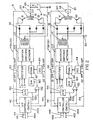
- FIGURE 1 A variety of controllers and power supplies could be used for practicing the system as described in FIGURE 1 ; however, preferred implementation of the system is set forth in FIGURE 2 wherein power supply PSA is combined with controller and power supply 30 and power supply PSB is combined with controller and power supply 32. These two units are essentially the same in structure and are labeled with the same numbers when appropriate. Description of power supply PSA applies equally to power supply PSB.
- Inverter 100 has an input rectifier 102 for receiving three phase line current L1, L2, and L3.
- Output transformer 110 is connected through an output rectifier 112 to tapped inductor 120 for driving opposite polarity switches Q1, Q2.
- Controller 140a of power supply PSA and controller 140b of PSB are essentially the same, except controller 140a outputs timing information to controller 140b.
- Switching points or lines 142, 144 control the conductive condition of polarity switches Q1, Q2 for reversing polarity at the time indicated by the logic on lines 142, 144, as explained in more detail in Stava 6,111,216 incorporated by reference herein.
- the control is digital with a logic processor; thus, A/D converter 150 converts the current information on feedback line 16 or line 26 to controlling digital values for the level of output from error amplifier 152 which is illustrated as an analog error amplifier. In practice, this is a digital system and there is no further analog signal in the control architecture. As illustrated, however, amplifier has a first input 152a from converter 150 and a second input 152b from controller 140a or 140b.
- the current command signal on line 152b includes the wave shape or waveform required for the AC current across the arc at weld station WS. This is standard practice as taught by several patents of Lincoln Electric, such as Blankenship 5,278,390, incorporated by reference. See also Stava 6,207,929, incorporated by reference.
- the output from amplifier 152 is converted to an analog voltage signal by converter 160 to drive pulse width modulator 162 at a frequency controlled by oscillator 164, which is a timer program in the processor software.
- the shape of the waveform at the arcs is the voltage or digital number at lines 152b.
- the frequency of oscillator 164 is greater than 18 kHz.
- the total architecture of this system is digitized in the preferred embodiment of the present invention and does not include reconversion back into analog signal.
- This representation is schematic for illustrative purposes and is not intended to be limiting of the type of power supply used in practicing the present invention. Other power supplies could be employed.
- FIGURES 3 and 4 A background system utilizing the concepts of FIGURES 1 and 2 are illustrated in FIGURES 3 and 4 .
- Workpiece 200 is a seam in a pipe which is welded together by tandem electrodes 202, 204 and 206 powered by individual power supplies PS1, PS2, PS3, respectively.
- the power supplies can include more than one power source coordinated in accordance with the technology in Houston 6,472,634.
- the illustrated embodiment involves a DC arc for lead electrode 202 and an AC arc for each of the tandem electrodes 204, 206.
- the created waveforms of the tandem electrodes are AC currents and include shapes created by a wave shaper or wave generator in accordance with the previously described waveform technology.
- molten metal puddle P is deposited in pipe seam 200 with an open root portion 210 followed by deposits 212, 214 and 216 from electrodes 202, 204 and 206, respectively.
- the power supplies as shown in FIGURE 4 , each include an inverter 220 receiving a DC link from rectifier 222.
- a chip or internal programmed pulse width modulator stage 224 is driven by an oscillator 226 at a frequency greater than 18 kHz and preferably greater than 20 kHz.
- the output current has a shape dictated by the wave shape outputted from wave shaper 240 as a voltage or digital numbers at line 242.
- Output leads 217, 218 are in series with electrodes 202, 204 and 206.
- the shape in real time is compared with the actual arc current in line 232 from Hall Effect transducer 228 by a stage illustrated as comparator 230 so that the outputs on line 234 controls the shape of the AC waveforms.
- the digital number or voltage on line 234 determines the output signal on line 224a to control inverter 220 so that the waveform of the current at the arc follows the selected profile outputted from wave shaper 240.
- This is standard Lincoln waveform technology, as previously discussed.
- Power supply PS1 creates a DC arc at lead electrode 202; therefore, the output from wave shaper 240 of this power supply is a steady state indicating the magnitude of the DC current.
- the present invention does not relate to the formation of a DC arc. To the contrary, the present invention is the control of the current at two adjacent AC arcs for tandem electrodes, such as electrodes 204, 206.
- wave shaper 240 involves an input 250 employed to select the desired shape or profile of the AC waveform.
- Wave shaper 240 has an output which is a priority signal on line 254.
- the priority signal is a bit of logic, as shown in FIGURE 7 .
- Logic 1 indicates a negative polarity for the waveform generated by wave shaper 240 and logic 0 indicates a positive polarity.
- This logic signal or bit controller 220 directed to the power supply is read in accordance with the technology discussed in FIGURE 16 .
- the inverter switches from a positive polarity to a negative polarity, or the reverse, at a specific "READY" time initiated by a change of the logic bit on line 254. In practice, this bit is received from variable pulse generator 80 shown in FIGURE 1 and in FIGURE 5 .
- the background welding system shown in FIGURES 3 and 4 uses the shapes of AC arc currents at electrodes 204 and 206 to obtain a beneficial result, i.e. a generally quiescent molten metal puddle P and/or synthesized sinusoidal waveforms compatible with transformer waveforms used in arc welding.
- the electric arc welding system shown in FIGURES 3 and 4 have a program to select the waveform at "SELECT" program 250 for wave shaper 240.
- the unique waveforms are used by the tandem electrodes.
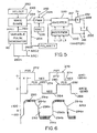
- One of the power supplies to create an AC arc is schematically illustrated in FIGURE 5 .
- the power supply or source is controlled by variable pulse generator 80, shown in FIGURE 1 .
- Signal 260 from the generator controls the power supply for the first arc.
- This signal includes the synchronization of the waveform together with the polarity bit outputted by the wave shaper 240 on line 254.
- Lines 260a-260n control the desired subsequent tandem AC arcs operated by the welding system of the present invention. The timing of these signals shifts the start of the other waveforms.
- FIGURE 5 merely shows the relationship of variable pulse generator 80 to control the successive arcs as explained in connection with FIGURE 4 .
- the AC waveforms are created as shown in FIGURE 6 wherein the wave shaper for arc AC1 at electrode 204 creates a signal 270 having positive portions 272 and negative portions 274.
- the second arc AC2 at electrode 206 is controlled by signal 280 from the wave shaper having positive portions 282 and negative portions 284. These two signals are the same, but are shifted by the signal from generator 80 a distance x, as shown in FIGURE 6 .
- the waveform technology created current pulses or waveforms at one of the arcs are waveforms having positive portions 290 and negative portions 292 shown at the bottom portion of FIGURE 6 .
- a logic bit from the wave shaper determines when the waveform is switched from the positive polarity to the negative polarity and the reverse.
- pulse width modulator 224 is generally shifted to a lower level at point 291 a and 291 b. Then the current reduces until reaching a fixed level, such as 100 amps. Consequently, the switches change polarity at points 294a and 294b. This produces a vertical line or shape 296a, 296b when current transitioning between positive portion 290 and negative portion 292. This is the system disclosed in the Houston patent where the like waveforms are shifted to avoid magnetic interference.
- the waveform portions 290, 292 are the same at arc AC1 and at arc AC2.
- FIGURE 6 is set forth to show the concept of shifting the waveforms. The same switching procedure to create a vertical transition between polarities is used in the preferred embodiment of the present invention. Converting from the welding system shown in FIGURE 6 to an imbalance waveform is generally shown in FIGURE 7 .
- the logic on line 254 is illustrated as being a logic 1 in portions 300 and a logic 0 in portions 302. The change of the logic or bit numbers signals the time when the system illustrated in FIGURE 16 shifts polarity.
- Wave shaper 240 for each of the adjacent AC arcs has a first wave shape 310 for one of the polarities and a second wave shape 312 for the other polarity.
- Each of the waveforms 310, 312 are created by the logic on line 234 taken together with the logic on line 254.
- pulses 310, 312 as shown in FIGURE 7 are different pulses for the positive and negative polarity portions.
- Each of the pulses 310, 312 are created by separate and distinct current pulses 310a, 312a as shown.
- FIGURE 6 Switching between polarities is accomplished as illustrated in FIGURE 6 where the waveforms generated by the wave shaper are shown as having the general shape of waveforms 310, 312. Positive polarity controls penetration and negative polarity controls deposition.
- the positive and negative pulses of a waveform are different and the switching points are controlled so that the AC waveform at one arc is controlled both in the negative polarity and the positive polarity to have a specific shape created by the output of wave shaper 240.
- the waveforms for the arc adjacent to the arc having the current shown in FIGURE 7 is controlled differently to obtain the advantages illustrated best in FIGURE 8 .
- the waveform at arc AC 1 is in the top part of FIGURE 8 .
- Positive portion 320 has a maximum magnitude a and width or time period b.
- Negative portion 322 has a maximum magnitude d and a time or period c. These four parameters are adjusted by wave shaper 240.
- arc AC2 has the waveform shown at the bottom of FIGURE 8 where positive portion 330 is formed by current pulses 330a and has a height or magnitude a' and a time length or period b'.
- Negative portion 332 is formed by pulses 332a and has a maximum amplitude d' and a time length c'. These parameters are adjusted by wave shaper 240.
- the waveform from the wave shaper on arc AC1 is out of phase with the wave shape for arc AC2.
- the two waveforms have parameters or dimensions which are adjusted so that (a) penetration and deposition is controlled and (b) there is no long time during which the puddle P is subjected to a specific polarity relationship, be it a like polarity or opposite polarity.
- This concept in formulating the wave shapes prevents long term polarity relationships as explained by the showings in FIGURES 9 and 10 .
- electrodes 204, 206 have like polarity, determined by the waveforms of the adjacent currents at any given time.
- magnetic flux 350 of electrode 204 and magnetic flux 352 of electrode 206 are in the same direction and cancel each other at center area 354 between the electrodes.
- This inward movement together or collapse of the molten metal in puddle P between electrodes 204 will ultimately cause an upward gushing action, if not terminated in a very short time, i.e. less than about 20 ms.
- the opposite movement of the puddle occurs when the electrodes 204, 206 have opposite polarities.
- the waveform accomplishes the objective of preventing long term concurrence of specific polarity relationships, be it like polarities or opposite polarities.
- like polarity and opposite polarity is retained for a very short time less than the cycle length of the waveforms at arc AC1 and arc AC2.
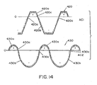
- the positive and negative portions of the AC waveform from the wave shaper 240 are synthesized sinusoidal shapes with a different energy in the positive portion as compared to the negative portion of the waveforms.
- the synthesized sine wave or sinusoidal portions of the waveforms allows the waveforms to be compatible with transformer welding circuits and compatible with evaluation of sine wave welding.
- waveform 370 is at arc AC1 and waveform 372 is at arc AC2.
- These tandem arcs utilize the AC welding current shown in FIGURE 11 wherein a small positive sinusoidal portion 370a controls penetration at arc AC1 while the larger negative portion 370b controls the deposition of metal at arc AC1.
- Sinusoidal waveform 370 plunges vertically from approximately 100 amperes through zero current as shown in by vertical line 370c. Transition between the negative portion 370b and positive portion 370a also starts a vertical transition at the switching point causing a vertical transition 370d.
- phase shifted waveform 372 of arc AC2 has a small penetration portion 372a and a large negative deposition portion 372b. Transition between polarities is indicated by vertical lines 372c and 372d.
- Waveform 372 is shifted with respect to waveform 370 so that the dynamics of the puddle are controlled without excessive collapsing or repulsion of the molten metal in the puddle caused by polarities of adjacent arcs AC1, AC2.
- the sine wave shapes are the same and the frequencies are the same. They are merely shifted to prevent a long term occurrence of a specific polarity relationship.
- waveform 380 is used for arc AC1 and waveform 382 is used for arc AC2.
- Portions 380a, 380b, 382a, and 382b are sinusoidal synthesized and are illustrated as being of the same general magnitude. By shifting these two waveforms 90o, areas of concurrent polarity are identified as areas 390, 392, 394 and 396. By using the shifted waveforms with sinusoidal profiles, like polarities or opposite polarities do not remain for any length of time. Thus, the molten metal puddle is not agitated and remains quiescent. This advantage is obtained by using the present invention which also combines the concept of a difference in energy between the positive and negative polarity portions of a given waveform.
- FIGURE 12 is illustrative in nature to show the definition of concurrent polarity relationships and the fact that they should remain for only a short period of time.
- FIGURE 13 another embodiment of the present invention is illustrated in FIGURE 13 wherein previously defined waveform 380 is combined with waveform 400, shown as the sawtooth waveform of arc AC2 (a) or the pulsating waveform 402 shown as the waveform for arc AC2(b).
- waveform 380 with the different waveform 400 of a different waveform 402 produces very small areas or times of concurrent polarity relationships 410, 412, 414, etc.
- FIGURE 14 the AC waveform generated at one arc is drastically different than the AC waveform generated at the other arc.
- waveform 420 is an AC pulse profile waveform and waveform 430 is a sinusoidal profile waveform having about one-half the period of waveform 420.
- Waveform 420 includes a small penetration positive portion 420a and a large deposition portion 420b with straight line polarity transitions 420c.
- Waveform 430 includes positive portion 430a and negative portion 430b with vertical polarity transitions 430c.
- waveforms 450, 452, 454 and 456 are generated by the wave shaper 240 of the power supply for each of four tandem arcs, arc AC1, arc AC2, arc AC3 and arc AC4.
- the adjacent arcs are aligned as indicated by synchronization signal 460 defining when the waveforms correspond and transition from the negative portion to the positive portion.
- This synchronization signal is created by generator 80 shown in FIGURE 1 , except the start pulses are aligned.
- first waveform 450 has a positive portion 450a, which is synchronized with both the positive and negative portion of the adjacent waveform 452, 454 and 456.
- positive portion 450a is synchronized with and correlated to positive portion 452a and negative portion 452b of waveform 452.
- the positive portion 452a of waveform 452 is synchronized with and correlated to positive portion 454a and negative portion 454b of waveform 454.
- the negative portion 450b is synchronized with and correlated to the two opposite polarity portions of aligned waveform 452.
- the collapse and repelling forces of puddle P are diametrically controlled.
- One or more of the positive or negative portions can be synthesized sinusoidal waves as discussed in connection with the waveforms disclosed in FIGURES 11 and 12 .
- a switch command is issued to master controller 140a of power supply 30. This causes a "kill" signal to be received by the master so a kill signal and polarity logic is rapidly transmitted to the controller of one or more slave power supplies connected in parallel with a single electrode.
- the slave controller or controllers are immediately switched within 1-10 ⁇ s after the master power supply receives the switch command. This is the advantage of the high accuracy interface cards or gateways. In practice, the actual switching for current reversal of the paralleled power supplies is not to occur until the output current is below a given value, i.e. about 100 amperes. This allows use of smaller switches.
- the implementation of the switching for all power supplies for a single AC arc uses the delayed switching technique where actual switching can occur only after all power supplies are below the given low current level.
- the delay process is accomplished in the software of the digital processor and is illustrated by the schematic layout of FIGURE 16 .
- the controller of master power supply 500 receives a command signal as represented by line 502, the power supply starts the switching sequence.
- the master outputs a logic on line 504 to provide the desired polarity for switching of the slaves to correspond with polarity switching of the master.
- the inverter of master power supply 500 is turned off or down so current to electrode E is decreased as read by hall effect transducer 510.
- the switch command in line 502 causes an immediate "kill" signal as represented by line 512 to the controllers of paralleled slave power supplies 520, 522 providing current to junction 530 as measured by hall effect transducers 532, 534. All power supplies are in the switch sequence with inverters turned off or down.
- Software comparator circuits 550, 552, 554 compare the decreased current to a given low current referenced by the voltage on line 556. As each power supply decreases below the given value, a signal appears in lines 560, 562, and 564 to the input of a sample and hold circuits 570, 572, and 574, respectively.
- the circuits are outputted by a strobe signal in line 580 from each of the power supplies.
- a YES logic appears on lines READY 1 , READY 2 , and READY 3 at the time of the strobe signal.
- This signal is generated in the power supplies and has a period of 25 ⁇ s; however, other high speed strobes could be used.
- the signals are directed to controller C of the master power supply, shown in dashed lines in FIGURE 16 .
- a software ANDing function represented by AND gate 584 has a YES logic output on line 582 when all power supplies are ready to switch polarity. This output condition is directed to clock enable terminal ECLK of software flip flop 600 having its D terminal provided with the desired logic of the polarity to be switched as appearing on line 504.
- Other circuits can be used to effect the delay in the switching sequence; however, the illustration in FIGURE 16 is the present scheme.
- the welder and/or welding system as shown in FIGURES 4 and 5 is operated by control program 700 used to accurately set the exact profile of a given waveform for use with a specific cored electrode shown in FIGURES 19 and 20 .
- Program 700 is illustrated in FIGURE 17 , where welder W has a wave shaper 240 set to a general type of weld waveform by a select network 250.
- the selected waveform is the desired AC waveform to perform, by a succession of waveforms, a given welding process.
- This waveform, in accordance with the invention, is set to be used with a specific cored electrode.
- Waveform control program 700 has a profile control network 710 to set the exact, desired profile of the waveform and a magnitude control circuit 712 to adjust the energy or power of the waveform without substantially changing the set profile to be used for a given cored electrode.
- This specific profile is stored in the welder disclosed in FIGURES 21 and 28 for use when the corresponding electrode is to be used in the welding process.
- the program or control network 700 is connected to the wave shaper 240 to control the exact general profile of each individual waveform in the succession of waveforms constituting an AC welding process.
- the first parameter is frequency set into the waveform profile by circuit 720 manually or automatically adjusted by interface network 722 to produce a set value on an output represented as line 724. This value controls the set frequency of the waveform profile. Of course, this is actually the period of the waveform.
- the duty cycle of the waveform is controlled by circuit 730 having an adjustable interface network 732 and an output line 734 for developing a value to control the relationship between the positive half cycle and the negative half cycle.
- This profile parameter is set by the logic or data on line 754 from circuit 730.
- the AC profile of the waveform is set. This does not relate to the energy level of the individual portions of the waveform, but merely the general fixed profile of the waveform.
- a circuit 742 having a manual or automatic adjusting network 742 and an output signal on line 744 for setting the rate at which the set profile of the waveform changes from negative to a positive polarity.
- a down ramp circuit 750 is provided with an adjusting interface 752 and an output line 754.
- the magnitudes of the values on lines 724, 734, 744 and 754 set the profile of the individual waveform. At least two of these parameter profiles are set together; however, preferably all of the profile parameters are set to define a waveform profile.
- program 700 includes magnitude circuit or network 712 divided into two individual sections 760, 762. These sections of the magnitude circuit control the energy or other power related level of the waveform during each of the polarities without substantially affecting the general profile set by profile control network 710.
- Section 760 includes a level control circuit 770 which is manually adjusted by an interface network 772 to control the relationship between an input value on line 774 and an output value on line 776.
- Level control circuit 770 is essentially a digital error amplifier circuit for controlling the current, voltage and/or power during the positive portion of the generated set waveform profile. Selector 250a shifts circuit 770 into either the current, voltage or power mode.
- Section 760 controls the energy, or power or other heat level during the positive portion of the waveform with changing the general profile set by network 710.
- second section 762 has a digital error amplifier circuit 760 that is set or adjusted by network 782 so that the value on input line 784 controls the level or signal on output line 786. Consequently, the digital level data on lines 776 and 786 controls the current, voltage and/or power during each of the half cycles set by profile control network 710.
- wave shaper 240 is controlled by only magnitude control circuit 712 and the profile is set by network or program 250 used in the background system shown in FIGURES 4 and 5 .
- Network 250 does not set the profile, but selects known types of waveforms as will be explained with the disclosure of FIGURES 21 and 28.
- the enhanced advantage of program 700 is realized by setting all profile parameters using circuits 720, 730, 740 and 750 together with the magnitude circuits 770, 780.
- a waveform controlled by any one of these circuits is an improvement over the background technology.
- Program 700 synergistically adjusts all profile parameters and magnitude values during each polarity of the AC waveform so the waveform corresponds to a specific cored electrode.
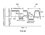
- Waveform 800 has a positive portion 802 and a negative portion 804, both produced by a series of rapidly created current pulses 800a.
- Waveform 800 is illustrated as merely a square wave to illustrate control of the frequency or period of the waveform and the ratio of the positive portion 802 to the negative portion 804.
- These parameters are accurately set by using program 700 to modify the type of waveform heretofore merely selected by network 450.
- the up ramp rate and the down ramp rate are essentially zero.
- the switching concept taught in Stava 6,111,216 would be employed for shifting between positive and negative waveform portions to obtain the advantages described in the Stava patent.
- Second illustrated waveform 810 has a frequency f, a positive portion 812 and a negative portion 814.
- the up ramp rate 816 is controlled independently of the down ramp rate 818.
- These ramp rates are illustrated as arrows to indicate they exist at the leading and trailing edges of the waveform during shifts between polarities.
- Program 700 relates to physically setting the exact profile of the individual waveforms by circuits 720, 730, 740 and 750.
- Several parameters of the waveform are adjusted to essentially "paint" the waveform into a desired profile.
- a very precise welding process using a set general profile for the AC waveform is performed by a waveform technology controlled welder using program 700. This program is used to "paint" a waveform for each individual cored electrode so there is a match between the AC waveform and the electrode used in the welding process.
- Program 700 in FIGURE 17 is used to construct or create AC waveforms that are optimized and specially tailored for each of individually identified cored electrode such as electrode 910 shown in FIGURES 19 and 20 .
- a welder 900 has torch 902 for directing electrode 910 toward workpiece WP.
- An arc AC is created between the end of electrode 910 and workpiece WP.
- the electrode is a cored electrode with sheath 912 and internal filled core 914.
- the core includes flux ingredients, such as represented by particles 914a.
- ingredients 914a are to (a) shield the molten weld metal from atmospheric contamination by covering the molten metal with slag, (b) combine chemically with any atmospheric contaminants such that their negative impact on the weld quality is minimized and/or (c) generate arc shielding gases.
- core 914 also includes alloying ingredients, referred to as particles 914b, together with other miscellaneous particles 914c that are combined to provide the fill of core 914.
- specific alloys are required, which can be difficult to obtain in the form of a solid wire.
- the present invention overcomes these difficulties by using a program such as program 700 shown in FIGURE 17 so a precise AC waveform is generated for the welding operation and correlated specifically to a given cored electrode.
- a program such as program 700 shown in FIGURE 17 so a precise AC waveform is generated for the welding operation and correlated specifically to a given cored electrode.
- the welding operation is optimized. It is now possible to use an AC welding operation with a waveform accurately profiled to accommodate a specific cored electrode.
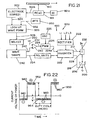
- Welder 900 is constructed in accordance with the present invention for performing an AC welding operation using a cored electrode so the welding operation is optimized for the particular electrode. Details of welder 900 are shown in FIGURE 21 where power source 920 is driven by rectifier 920a. Electrode 910 is a cored electrode with sheath 912 and core 914. Power source 920 of welder 900 has a storage device, unit or circuit 922 to create an electrode identification signal in line 924 to identify a particular electrode 910 being used in the welding process. Reading device 921 identifies the particular electrode 910 passing by the reading device as indicated at the top of FIGURE 21 . Thus, the signal in line 924 identifies electrode 910.
- Device 921 a manually tells reading device 921 which particular electrode 910 is being used.
- reading device 921 is set to the particular cored electrode 910 to be used in the welding operation. This device is manually adjusted to indicate a specific electrode.
- Electrode 910 can be identified by storage device 922 by a bar code or other reading technique. The bar code is located on the spool or drum containing electrode wire 910.
- device 921 either automatically senses the identification of wire or electrode 910 or receives manual input to indicate the electrode as indicated by block 921 a.
- a signal in 921 b is directed to storage device 922 where a signal in data form is stored for all electrodes to be used by welder 900.
- the signal on line 921b addresses a particular data in storage device 922 corresponding with the specific cored electrode.
- This data causes a profile signal to be applied to line 924.
- This signal activates waveform look up device 926 so the device outputs a profile signal in line 928.
- This signal instructs select circuit 250 to select a particular stored profile which has been created by program 700 for a particular cored electrode.
- Program 700 shown in FIGURE 17 tailors the stored waveforms to a specific electrode.
- the remainder of power source 920 has been previously described.
- the profile signal in line 928 selects a specific constructed or created waveform stored in a memory associated with circuit 250.
- An AC welding waveform tailored to the particular construction and constituents of a particular cored electrode 910 is outputted in line 242.
- the particular signal in line 928 is determined by the electrode and the wire feed speed.
- Device 930 has a set point that is outputted in line 932. Consequently, the logic or data on lines 924 and 932 determine the profile select signal in line 928.
- a desired stored profile in the memory of waveform generator 250 is used. This profile is based upon the particular electrode and/or the particular set point wire feed speed.
- a typical constructed AC waveform is illustrated in FIGURE 22 where process curve 950 includes a series of waveforms comprising positive section 952 and negative section 954.
- the waveforms are created by a large number of individual pulses 960 created at a rate substantially greater than 18 kHz and created at the output line 224a of pulse width modulator 224.
- curve 950 has a positive magnitude x and a negative magnitude y with the length of the negative portion 954 indicated to be z.
- duty cycle z is adjusted when the waveform shown in FIGURE 22 is constructed for a particular cored electrode.
- the negative portion 954 of FIGURE 22 controls the overall heat input to the workpiece.
- the positive portion 952 contributes more heat to the electrode and less heat to the workpiece. Therefore, by changing the duty cycle, the overall heat into the workpiece can be varied or controlled.
- an AC welding process is created at the output of wave shaper or waveform generator 240. The selected waveform is precisely adjusted to optimize its use with a particular cored electrode 910.
- the waveform has duty cycle of z controlled by program 700. After the waveform has been fixed, it is set into waveform generator 240 based upon the logic from select circuit 250. Welder 900 is used to correlate a particular AC waveform with a particular cored electrode to fix the operation of the welding process dictated by the constituents forming electrode 910.
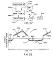
- the waveform used in practicing the invention is preferably a square waveform as shown in FIGURE 22 ; however, to control the initial heating it is within the scope of the invention to provide a non-square AC waveform shown in FIGURE 23 wherein process curve 970 comprises waveforms, each having positive portion 972 and negative portion 974. Each of these portions is formed by a plurality of individual pulses 960 as explained with respect to curve 950 in FIGURE 22 . These individual pulses 960 are created at a frequency greater than 18 kHz and are waveform technology pulses normally used in inverter type power sources. To reduce the rate of heating, portions 972, 974 are provided with ramp portions 976, 977, 978 and 979. Other profiles are possible to optimize the AC welding using the present invention.
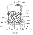
- FIGURE 24 A problem caused when using cored electrodes without implementation of the present invention is illustrated in FIGURE 24 .
- the welding process melts sheath 912 to provide a portion of molten metal 980 melted upwardly around the electrode, as indicated by melted upper end 982..
- the sheath of the electrode is melted more rapidly than the core.
- This causes a molten metal material to exist at the output end of electrode 910 without protective gas or chemical reaction created by melting of the internal constituents of core 914.
- arc AC melts the metal of electrode 910 in an unprotected atmosphere.
- the necessary shielding for the molten metal is formed when the sheath and core are melted at the same rate.
- FIGURE 25 The problem of melting the molten metal more rapidly than the core is further indicated by the pictorial representation of FIGURE 25 .
- Molten metal 990 from sheath 912 has already joined workpiece WP before the core has had an opportunity to be melted. It can not provide the necessary shielding for the welding process.
- FIGURES 24 and 25 show the reason why AC welding using cored electrodes has not been used for off-shore pipeline welding and other pipeline welding.
- the invention proposes the use of an AC waveform as described above as a means to control the heat input when using a cored electrode.
- the precise profile for the AC waveform used in the welding process is selected whereby sheath 912 and core 914 melt at approximately the same rate.
- the failure to adequately coordinate the melting of the shield with the melting of the core would be a reason for rejecting the use of AC welding with cored electrodes for pipeline welding.
- the advantage of the invention is a process not needing external shielding gas. When this occurs, shielding gas SG and other shielding constituents are generated ahead of the molten metal from sheath 912.
- this feature can be obtained by precisely profiling the waveform for the welding operation using program 700. In the past such coordination was not possible.
- Invention of program 700 or like programs made the present invention possible. These programs generate waveforms which are specifically tailored for individual cored electrodes allowing cored electrodes to be used in an AC welding process in a manner to protect the molten metal against atmospheric contamination during the welding operation.
- FIGURE 27 illustrates a situation where the sheath has melted more rapidly than the core.
- Molten metal 990 from sheath 912 has already joined workpiece WP before core 914 has had an opportunity to be melted.
- Metal 990 has not been protected from the effects of atmospheric contamination to the degree that it would have been if the unmelted core constituents had actually been melted. Additionally, alloying elements needed to achieve desired mechanical and metallurgical characteristics may be missing from molten metal 990.
- FIGURE 27 An alternative of the present invention is shown in FIGURE 27 where select circuit 992 selects a waveform B in accordance with the data in line 994a from block 994.
- This block has data identifying a particular electrode A.
- the electrode has a composition that is accommodated by waveform B in select circuit 992.
- a set point in line 996a from wire feed speed block 996 is used to select waveform B so that waveform B is not only a waveform for the electrode which is a primary aspect of the invention, but electrode A with a particular set point.
- This adjusts the output of waveform generator 240 to control the waveform of the AC welding process to be tailored to the exact cored electrode A identified by block 994.
- Electrode A is used to activate waveform B.
- the basic aspect of the invention is creation of a waveform to perform the desired operation when using a particular cored electrode.
- the desired welding process is performed between the electrode and the workpiece.
- Various analog and digital components are possible for performing the present invention.
- the constituents of the core and the size of the sheath determines the optimum waveform profile used in the AC welding process.
- This invention is made possible by the use of a program such as program 700 in FIGURE 17 to precisely set and modify the profile of the waveform being used in an electric arc welding process of the type using waveform technology.
Landscapes
- Engineering & Computer Science (AREA)
- Physics & Mathematics (AREA)
- Plasma & Fusion (AREA)
- Mechanical Engineering (AREA)
- Arc Welding Control (AREA)
- Generation Of Surge Voltage And Current (AREA)
- Arc Welding In General (AREA)
- Electrical Discharge Machining, Electrochemical Machining, And Combined Machining (AREA)
- Discharge Heating (AREA)
- Plasma Technology (AREA)
Claims (24)
- Elektrisches Lichtbogenschweißgerät (900) zur Schaffung eines Schweißprozesses in Form einer Folge von Wechselstrom-Wellenformen zwischen einer besonderen Art einer gefüllten Elektrode (910) mit einer Umhüllung (912) und einem Kern (914) und einem Werkstück (B) mittels einer Leistungsquelle (920), mit einer Hochfrequenz-Schaiteinrichturig zur Schaffung der individuellen Wellenformen in der Folge von Wellenformen, wobei jede Wellenform ein Profil aufweist, welches durch die Größe eines jeden aus einer großen Zahl von kurzen Stromimpulsen (960) gebildet ist, die bei einer Frequenz von mindestens 18 kHz erzeugt werden, wobei das Profil durch das Eingangssignal eines Wellenformers (240) zur Steuerung der kurzen Stromimpulse (960) bestimmt ist, und mit einem Schaltkreis zur Schaffung eines Profilsignals welches den besonderen Elektrodentyp (910) angibt, und mit einem Wählschaltkreis (250) zur Auswahl des auf dem Profilsignal basierenden Eingangssignals, mittels dessen der Wellenformer (240) die Leistungsquelle (920) zur Schaffung eines für den besonderen Typ von gefüllter Elektrode (910) spezifischen Wellenformprofils veranlasst.
- Elektrisches Lichtbogenschweißgerät nach Anspruch 1, bei dem der Wellenformer (240) einen lmpulsbreitenmodulator (224) steuert, um das Profil der ausgewählten Wellenform zu bestimmten.
- Elektrisches Lichtbogenschweißgerät nach Anspruch 1 oder 2, bei dem der Wählschaltkreis (250) eine Daten-Suchvorrichtung zur Ausgabe von Eingangssignalen ist, die auf dem Profilsignal basieren.
- Elektrisches Lichtbogenschweißgerät nach einem der Ansprüche 1 bis 3, bei dem die Hochgeschwindigkeits-Schalteinrichtung ein Inverter (220) ist.
- Elektrisches Lichtbogenschweißgerät nach einem der Ansprüche 1 bis 4, bei dem das gewählte Wellenformprofil die Umhüllung (912) und den Kern (914) ungefähr gleich schnell schmelzen lässt.
- Elektrisches Lichtbogenschweißgerät nach einem der Ansprüche 1 bis 5, bei dem das gewählte Wellenformprofil eine voreilende Flanke und einen Rampenteil (976, 977, 978, 997) an der voreilenden Kante zur Steuerung des Schmeizens der Umhüllung (912) aufweist.
- Elektrisches Lichtbogenschweißgerät nach einem der Ansprüche 1 bis 6, bei dem die Elektrode (910) einen Außendurchmesser aufweist und das gewählte Wellenformprofil die Bogenlänge zwischen der Elektrode (910) und dem Werkstück (W) auf weniger als das 1,5fache des Außendurchmessers der Elektrode (910) einsteuert.
- Elektrisches Lichtbogenschweißgerät nach einem der Ansprüche 1 bis 7, worin die Stromimpulse durch einen Impulsbreitenmodulator (224) derart erzeugt werden, dass die Größe der Stromimpulse durch einen Wellenformer (240) gesteuert werden und die Polarität jedes Teils der individuellen Wellenformen durch die Daten eines Polaritätssignals bestimmt werden,
mit folgenden weiteren Merkmalen:ein Profilsteuerungsnetzwerk (70) zur Bildung des allgemeinen Profils einer individuellen Wellenform durch Einstellung mehr als einen Profilparameters einer individuellen Wellenform, wobei die Parameter aus der Klasse ausgewählt sind, die aus Frequenz, Arbeitszyklus, Steigung der Aufwärtsflanke und Steigung der Abwärtsflanke besteht; undein Größenschaltkreis zur Anpassung der individuellen Wellenform bei der Einstellung des Gesamtstroms, der Spannung und/oder der Leistung ohne wesentlichen Einfluss auf das allgemeine feststehende Profil. - Elektrisches Lichtbogenschweißgerät nach einem der Ansprüche 1 bis 7, bei dem das Profil durch das Eingangssignal zu einem Wellenformer (240) bestimmt ist, der die kurzen Stromimpulse (960) steuert;
Mit den weiteren Merkmalen:eine Elektrodenspeichereinrichtung mit mehreren adressierbaren Datenblocks (994), die jeweils eine spezifische gefüllte Elektrode (910) anzeigen;eine Wähleinrichtung (992) mit einer Anzahl gespeicherter Wellenformsignale zur Einstellung eines gegebenen Wellenformprofils in den Wellenformer (240); undeinen Schaltkreis zur Ausgabe eines speziellen Datenblocks zur Auswahl eines gegebenen Wellenformsignals nach Auswahl der Adresse für die besondere gefüllte Elektrode (910). - Elektrisches Lichtbogenschweißgerät nach Anspruch 9, bei dem der Wellenformer (240) einen Impulsbreitenmodulator (224) steuert, um das Profil der gewählten Wellenform zu bestimmen.
- Elektrisches Lichtbogenschweißgerät nach Anspruch 10 mit einer Sollwertspeichereinrichtung, die mehrere Datenblocks enthält, die jeder einen Sollwert für eine spezifische Vorschubgeschwindigkeit des Drahtes angeben und bei dem die Wähleinrichtung sowohl auf den von der Elektrodenspeichereinrichtung ausgegebenen Datenblock als auch auf den von der Sollwertspeichereinrichtung ausgegebenen Datenblock anspricht.
- Elektrisches Lichtbogenschweißgerät nach einem der Ansprüche 9 bis 11, bei dem die gefüllte Elektrode (910) eine Flussmittel enthaltende Elektrode ist.
- Elektrisches Lichtbogenschweißgerät nach einem der Ansprüche 1 bis 12, bei dem die Wechselstrom-Wellenformen (950) jeweils einen positiven Teil (952) mit einer ersten Gestalt und einer ersten Zeitdauer sowie einen negativen Teil (954) mit einer zweiten Gestalt und einer zweiten Zeitdauer umfassen, bei dem entweder die erste oder die zweite Gestalt in ihrer Größe (x, y) größer als die jeweils andere Gestalt ist, und bei der die Zeitdauer der Gestalt mit der größeren Größe (x) wesentlich geringer als die Zeitdauer der anderen Gestalt ist.
- Verfahren zum Schweißen mit einer speziellen gefüllten Elektrode (910) mit einer Umhüllung (912) und einer Füllung (914) an einem Werkstück (W), mit folgenden Verfahrensschritten(a) Auswählen einer Wellenform mit einem spezifischen für das Schweißen mit der spezifischen Elektrode (910) zurechtgeschnittenen Profil;(b) Erzeugung einer Reihe von ausgewählten Wellenformen zur Schaffung eines Schweißprozesses; und(c) Schweißen mit der Elektrode (910) unter Einsatz des Schweißprozesses.
- Verfahren nach Anspruch 14, bei dem als Wellenform eine Wechselstrom-Wellenform gewählt ist.
- Verfahren nach Anspruch 15, bei dem eine Wechselstrom-Wellenform genutzt wird, die eine gegebene Polarität mit verringerter Größe für eine verlängerte Zeit zur Steuerung der Aufheizung bei dem Verfahren aufweist.
- Verfahren nach einem der Ansprüche 14 bis 16, bei dem eine Füllung (912) mit Legierungszusätzen eingesetzt wird.
- Verfahren nach einem der Ansprüche 14 bis 16, bei dem für die Schweißung ein bei einer Rate von mehr als 18 kHz geschalteter Inverter (220) eingesetzt wird.
- Verfahren nach einem der Ansprüche 14 bis 16, bei dem das ausgewählte Profil die Umhüllung (912) und die Füllung (914) mit ungefähr gleicher Geschwindigkeit schmelzen lässt.
- Verfahren nach einem der Ansprüche 14 bis 16, bei dem die Elektrode (910) einen äußeren Durchmesser aufweist und das ausgewählte Profil die Bogenlänge zwischen der Elektrode (910) und dem Werkstück (W) auf weniger als das 1,5fache des äußeren Durchmessers der Elektrode (910) einsteuert.
- Verfahren nach einem der Ansprüche 14 bis 16 mit folgenden weiteren Merkmalen:(d) Bestimmung der Polarität jedes Teils der individuellen Wellenformen durch die Daten eines Polaritätssignals;(e) Bestimmung des allgemeinen Profils einer individuellen Wellenform durch Einstellung mehr als eines Profil parameters der individuellen Form, wobei die Parameter aus der Gruppe Frequenz, Arbeitszyklus, Steigung der Aufwärtsflanke und Steigung der Abwärtsflanke ausgewählt sind; und(f) Anpassung des Wellenformprofils zur Einstellung der Gesamtgröße des Stroms, der Spannung und/oder Leistung ohne wesentliche Änderung des allgemeinen Profils.
- Verfahren nach Anspruch 21, bei dem als gefüllte Elektrode (910) eine Flussmittel enthaltende Elektrode eingesetzt wird.
- Verfahren nach einem der Ansprüche 14 bis 16, mit folgenden weiteren Merkmalen:(d) Bereitstellung keines Schutzgases (SG) für den Schweißprozess.
- Verfahren nach einem der Ansprüche 14 bis 16, bei dem eine Wellenform mit einem spezifischen, auf das Schweißen mit der spezifischen Elektrode (910) zugeschnittenen Profil ausgewählt wird, mit folgenden weiteren Merkmalen:(d) Erzeugung einer positiven Wellenform (952) mit einer ersten Gestalt und einer ersten Zeitdauer;(e) Erzeugung einer negativen Wellenform (954) mit einer zweiten Gestalt und einer zweiten Zeitdauer;(f) eine der ersten und zweiten Gestalten wird den ihrer Größe (x, y) größer als die andere der Gestalten gemacht;(g) Anpassung des Arbeitszyklus der ersten und zweiten Zeitdauer, so dass die Zeitdauer der Gestalt mit der größeren Größe (x) wesentlich geringer als die Zeitdauer der anderen Gestalt (y) ist.
Applications Claiming Priority (2)
| Application Number | Priority Date | Filing Date | Title |
|---|---|---|---|
| US834141 | 2004-04-29 | ||
| US10/834,141 US7166817B2 (en) | 2004-04-29 | 2004-04-29 | Electric ARC welder system with waveform profile control for cored electrodes |
Publications (2)
| Publication Number | Publication Date |
|---|---|
| EP1595634A1 EP1595634A1 (de) | 2005-11-16 |
| EP1595634B1 true EP1595634B1 (de) | 2008-07-30 |
Family
ID=34935271
Family Applications (1)
| Application Number | Title | Priority Date | Filing Date |
|---|---|---|---|
| EP20050008352 Expired - Lifetime EP1595634B1 (de) | 2004-04-29 | 2005-04-18 | Elektrische Lichtbogenvorrichtung mit einem gesteuerten Wellenformprofil für Kernelektroden |
Country Status (11)
| Country | Link |
|---|---|
| US (3) | US7166817B2 (de) |
| EP (1) | EP1595634B1 (de) |
| JP (1) | JP2005313229A (de) |
| KR (1) | KR100653660B1 (de) |
| CN (1) | CN100509237C (de) |
| AT (1) | ATE402780T1 (de) |
| AU (1) | AU2004226950B2 (de) |
| BR (1) | BRPI0405404A (de) |
| CA (1) | CA2486083C (de) |
| DE (1) | DE602005008504D1 (de) |
| MX (1) | MXPA04012366A (de) |
Families Citing this family (28)
| Publication number | Priority date | Publication date | Assignee | Title |
|---|---|---|---|---|
| US20080156782A1 (en) * | 2001-06-19 | 2008-07-03 | Illinois Tool Works Inc. | Method and Apparatus For Welding and Control Thereof |
| US7053334B2 (en) | 2004-03-01 | 2006-05-30 | Lincoln Global, Inc. | Electric arc welder system with waveform profile control |
| US8704135B2 (en) * | 2006-01-20 | 2014-04-22 | Lincoln Global, Inc. | Synergistic welding system |
| US9333580B2 (en) | 2004-04-29 | 2016-05-10 | Lincoln Global, Inc. | Gas-less process and system for girth welding in high strength applications |
| US8759715B2 (en) | 2004-10-06 | 2014-06-24 | Lincoln Global, Inc. | Method of AC welding with cored electrode |
| US7842903B2 (en) * | 2005-10-31 | 2010-11-30 | Lincoln Global, Inc. | Short arc welding system |
| US7166817B2 (en) * | 2004-04-29 | 2007-01-23 | Lincoln Global, Inc. | Electric ARC welder system with waveform profile control for cored electrodes |
| AT501489B1 (de) * | 2005-02-25 | 2009-07-15 | Fronius Int Gmbh | Verfahren zum steuern und/oder regeln eines schweissgerätes und schweissgerät |
| US7989732B2 (en) | 2005-06-15 | 2011-08-02 | Lincoln Global, Inc. | Method of AC welding using a flux cored electrode |
| RU2452779C2 (ru) | 2007-02-27 | 2012-06-10 | Эксонмобил Апстрим Рисерч Компани | Сварные конструкции из коррозионно-устойчивых сплавов в конструкциях из углеродистой стали и трубопроводах, выдерживающие высокие осевые пластические деформации |
| US8049141B2 (en) | 2007-07-18 | 2011-11-01 | Lincoln Global, Inc. | Method of rating a stick electrode |
| US8592722B2 (en) * | 2008-11-03 | 2013-11-26 | Illinois Tool Works Inc. | Weld parameter interface |
| US20110301733A1 (en) * | 2009-02-25 | 2011-12-08 | Panasonic Corporation | Welding method and welding system |
| CN102123812B (zh) * | 2009-04-08 | 2013-06-12 | 松下电器产业株式会社 | 电弧焊接方法及电弧焊接装置 |
| US20120285938A1 (en) * | 2011-05-10 | 2012-11-15 | Lincoln Global, Inc. | Flux cored arc welding system with high deposition rate and weld with robust impact toughness |
| EP2732901B1 (de) * | 2011-07-12 | 2018-08-08 | Panasonic Intellectual Property Management Co., Ltd. | Verfahren zur steuerung einer lichtbogenschweissung und lichtbogenschweissvorrichtung |
| US9527152B2 (en) | 2012-07-30 | 2016-12-27 | Illinois Tool Works Inc. | Root pass welding solution |
| US9393636B2 (en) * | 2012-11-13 | 2016-07-19 | Lincoln Global, Inc. | Systems and methods to facilitate the starting and stopping of arc welding processes |
| US10933486B2 (en) * | 2013-02-28 | 2021-03-02 | Illinois Tool Works Inc. | Remote master reset of machine |
| US9868172B2 (en) * | 2013-03-08 | 2018-01-16 | Lincoln Global, Inc. | Arc welding with waveform control function |
| US20140263232A1 (en) * | 2013-03-15 | 2014-09-18 | Lincoln Global, Inc. | Tandem hot-wire systems |
| US10173279B2 (en) | 2014-11-21 | 2019-01-08 | Lincoln Global, Inc. | Welding system |
| US10974341B2 (en) * | 2016-06-28 | 2021-04-13 | Lincoln Global, Inc. | Welding waveform for stainless steel applications |
| US10449615B2 (en) * | 2016-10-31 | 2019-10-22 | Illinois Tool Works Inc. | Hybrid welding modules |
| US10906117B2 (en) | 2018-01-30 | 2021-02-02 | Illinois Tool Works Inc. | System and method for providing welding type power on multiple outputs |
| US10710310B1 (en) * | 2019-08-15 | 2020-07-14 | Dukane Ias, Llc | Multipoint controllers for power delivery to multiple probes in ultrasonic welding systems |
| US20210129252A1 (en) * | 2019-11-01 | 2021-05-06 | Illinois Tool Works Inc. | Systems and methods to control welding-type power supplies using ac waveforms and/or dc pulse waveforms |
| US11919110B2 (en) | 2020-07-21 | 2024-03-05 | Esab Ab | Balance and offset in adaptive submerged arc welding |
Family Cites Families (110)
| Publication number | Priority date | Publication date | Assignee | Title |
|---|---|---|---|---|
| US2802762A (en) * | 1953-08-19 | 1957-08-13 | Solar Aircraft Co | Welding fluxes |
| US3177340A (en) * | 1961-11-24 | 1965-04-06 | Soudure Electr Autogene Sa | Flux-cored electrode and process of welding |
| CH469529A (de) * | 1964-08-06 | 1969-03-15 | Kobayashi Takuro | Elektrode aus Stahl für Lichtbogenschweissung ohne Luftausschluss |
| US3461270A (en) * | 1966-01-06 | 1969-08-12 | Lincoln Electric Co | Tubular welding electrode |
| GB1183461A (en) * | 1966-10-31 | 1970-03-04 | Murex Welding Processes Ltd | Improvements in Arc Welding |
| US3424892A (en) * | 1967-12-18 | 1969-01-28 | Arcos Corp | Process of electric arc welding |
| US3560702A (en) * | 1968-03-02 | 1971-02-02 | Kobe Steel Ltd | Composite electrode for consumable electrode arc welding process |
| US3566073A (en) * | 1968-04-03 | 1971-02-23 | Lincoln Electric Co | Out-of-position automatic cored welding electrode |
| US3596053A (en) * | 1969-07-28 | 1971-07-27 | Mitsubishi Heavy Ind Ltd | Consumable welding rod for welding chromium steels and the resultant welds |
| US3585343A (en) * | 1970-05-21 | 1971-06-15 | Union Carbide Corp | Method for vertical welding of aluminum |
| US3742185A (en) * | 1971-05-07 | 1973-06-26 | Lincoln Electric Co | Lithium containing welding electrode |
| US3670135A (en) * | 1971-06-02 | 1972-06-13 | Stoody Co | Arc welding electrode and process for stainless steel |
| BE790406A (de) * | 1971-11-03 | 1973-02-15 | Teledyne Inc | |
| US3786658A (en) * | 1972-06-23 | 1974-01-22 | Us Navy | Restrictive manipulation limited try mechanism for a combination lock |
| DE2364893C3 (de) * | 1972-12-29 | 1979-12-06 | Nippon Steel Corp., Tokio | Seelenelektrode zum automatischen oder halbautomatischen Lichtbogenschweißen von Stahl |
| US3883713A (en) * | 1973-04-25 | 1975-05-13 | Samuil Gurevich | Flux cored electrode |
| NL176060B (nl) * | 1974-02-08 | 1984-09-17 | Philips Nv | Lasinrichting voor kortsluitbooglassen. |
| US4010309A (en) * | 1974-06-10 | 1977-03-01 | The International Nickel Company, Inc. | Welding electrode |
| US4072845A (en) * | 1975-07-28 | 1978-02-07 | Boc Limited | Welding electrode |
| GB1539917A (en) * | 1976-03-08 | 1979-02-07 | Boc Ltd | Methods of arc welding in a super-atmospheric environment |
| JPS5367657A (en) * | 1976-11-29 | 1978-06-16 | Osaka Denki Co Ltd | Arc welding power source device |
| US4149063A (en) * | 1977-03-28 | 1979-04-10 | The International Nickel Company, Inc. | Flux cored wire for welding Ni-Cr-Fe alloys |
| SU764902A1 (ru) * | 1977-06-06 | 1980-10-02 | Ордена Ленина И Ордена Трудового Красного Знамени Институт Электросварки Им. Е.О.Патона | Способ электрошлаковой сварки легких металлов |
| US4186293A (en) * | 1978-05-08 | 1980-01-29 | The Lincoln Electric Company | Cored type welding electrode |
| US4214145A (en) * | 1979-01-25 | 1980-07-22 | Stoody Company | Mild steel, flux-cored electrode for arc welding |
| US4246463A (en) * | 1979-02-13 | 1981-01-20 | The Lincoln Electric Company | Method and apparatus for arc welding of metal plates from one side only |
| SE416625B (sv) * | 1979-03-01 | 1981-01-26 | Thermal Dynamics Corp | Anordning for spraybagsvetsning |
| US4314136A (en) * | 1980-04-16 | 1982-02-02 | Teledyne Industries, Inc. | Tubular composite arc welding electrode for vertical up welding of stainless steel |
| US4449031A (en) * | 1980-04-16 | 1984-05-15 | Teledyne Industries, Inc. | Tubular composite arc welding electrode for vertical up welding of stainless steel and nickel-base alloys |
| JPS5719185A (en) * | 1980-07-08 | 1982-02-01 | Mitsubishi Electric Corp | Pulse arc welding device |
| US4376881A (en) * | 1981-01-29 | 1983-03-15 | Safonnikov Anatoly N | Method of electroslag welding with a plate electrode |
| JPS5944159B2 (ja) * | 1981-06-05 | 1984-10-26 | 株式会社神戸製鋼所 | ガスシ−ルドア−ク溶接用フラツクス入りワイヤ |
| US4454406A (en) * | 1982-02-23 | 1984-06-12 | Institut Elektrosvarki Imeni E.O. Patona Akademii Nauk Ukrainskoi Ssr | Method, welding flux, and apparatus for electroslag welding |
| US4465036A (en) * | 1982-08-12 | 1984-08-14 | Forbes Edward K | Internal combustion engine |
| JPS59104291A (ja) * | 1982-12-06 | 1984-06-16 | Kobe Steel Ltd | ガスシ−ルドア−ク溶接用フラツクス入りワイヤ |
| US4551610A (en) * | 1983-05-17 | 1985-11-05 | The Lincoln Electric Company | Tubular welding electrode |
| US4571480A (en) * | 1984-02-27 | 1986-02-18 | Kabushiki Kaisha Kobe Seiko Sho | Flux cored wire electrodes for self-shielded arc welding |
| US4512822A (en) * | 1984-06-29 | 1985-04-23 | Massachusetts Institute Of Technology | Non-hygroscopic welding flux binders |
| US4800131A (en) * | 1984-12-20 | 1989-01-24 | Alloy Rods Global, Inc. | Cored wire filler metals and a method for their manufacture |
| US4689461A (en) * | 1985-09-25 | 1987-08-25 | Eutectic Corporation | Cored tubular electrode and method for the electric-arc cutting of metals |
| US4717536A (en) * | 1986-01-24 | 1988-01-05 | The Lincoln Electric Company | Weld bead electrode for producing same and method of use |
| US4803340A (en) * | 1986-04-23 | 1989-02-07 | Kawasaki Steel Corp. | Covered arc-welding electrode |
| US4723061A (en) * | 1986-07-31 | 1988-02-02 | The Lincoln Electric Company | Gas shielded, flux cored, welding electrode |
| US5005655A (en) * | 1986-12-03 | 1991-04-09 | Conoco Inc. | Partially halogenated ethane solvent removal of oleophylic materials from mineral particles |
| US4954691A (en) * | 1986-12-10 | 1990-09-04 | The Lincoln Electric Company | Method and device for controlling a short circuiting type welding system |
| US4717807A (en) * | 1986-12-11 | 1988-01-05 | The Lincoln Electric Company | Method and device for controlling a short circuiting type welding system |
| US4866247A (en) * | 1986-12-11 | 1989-09-12 | The Lincoln Electric Company | Apparatus and method of short circuiting arc welding |
| US5015823A (en) * | 1986-12-12 | 1991-05-14 | The Lincoln Electric Company | High manganese containing weld bead and electrode for producing same |
| US4833296A (en) * | 1987-12-29 | 1989-05-23 | The Lincoln Electric Company | Consumable welding electrode and method of using same |
| EP0396743A1 (de) * | 1988-07-26 | 1990-11-14 | Institut Elektrosvarki Imeni E.O.Patona Akademii Nauk Ukrainskoi Ssr | Elektrodendraht |
| US4948936A (en) * | 1988-09-28 | 1990-08-14 | Gulf Engineering Company, Inc. | Flux cored arc welding process |
| DE4023155C2 (de) * | 1989-07-21 | 1997-02-06 | Hitachi Seiko Kk | Wechselstrom-Schutzgaslichtbogenschweißverfahren und Vorrichtung mit verbrauchbarer Elektrode |
| US5091628A (en) * | 1989-09-11 | 1992-02-25 | The Lincoln Electric Company | Low hydrogen basic metal cored electrode |
| US5225661A (en) * | 1989-09-11 | 1993-07-06 | The Lincoln Electric Company | Basic metal cored electrode |
| US5003155A (en) * | 1989-09-11 | 1991-03-26 | The Lincoln Electric Company | Basic metal cored electrode |
| US5055655A (en) * | 1989-09-11 | 1991-10-08 | The Lincoln Electric Company | Low hydrogen basic metal cored electrode |
| US5369244A (en) * | 1989-09-11 | 1994-11-29 | The Lincoln Electric Company | Flux cored arc welding electrode |
| JP3003159B2 (ja) * | 1989-12-28 | 2000-01-24 | 株式会社ダイヘン | 交流アーク溶接用電源 |
| JPH03243296A (ja) * | 1990-02-22 | 1991-10-30 | Kobe Steel Ltd | ステンレス鋼用フラックス入りワイヤ |
| US5124530A (en) * | 1990-03-22 | 1992-06-23 | Inco Alloys International, Inc. | Stable low fume stainless steel welding electrode |
| US5304346A (en) * | 1990-10-26 | 1994-04-19 | Inco Alloys International, Inc. | Welding material for low coefficient of thermal expansion alloys |
| US5140140A (en) * | 1990-11-15 | 1992-08-18 | Pollack Alex J | Method and apparatus of submerged arc welding with electrodes in tandem |
| US5120931A (en) * | 1991-04-12 | 1992-06-09 | The Lincoln Electric Company | Electrode and flux for arc welding stainless steel |
| US5308698A (en) * | 1992-05-21 | 1994-05-03 | Inco Alloys International, Inc. | Flux for coated welding electrode |
| US5365036A (en) * | 1992-06-22 | 1994-11-15 | The Lincoln Electric Company | Flux cored gas shielded electrode |
| US5233160A (en) * | 1992-06-22 | 1993-08-03 | The Lincoln Electric Company | Cored electrode with fume reduction |
| US5278390A (en) * | 1993-03-18 | 1994-01-11 | The Lincoln Electric Company | System and method for controlling a welding process for an arc welder |
| JPH0938772A (ja) * | 1995-07-31 | 1997-02-10 | Kobe Steel Ltd | 交流セルフシールドアーク溶接方法 |
| US5981906A (en) * | 1995-08-11 | 1999-11-09 | Lincoln Global, Inc. | Method of welding the ends of pipe together using dual welding wires |
| US5676857A (en) * | 1995-08-11 | 1997-10-14 | Sabre International, Inc. | Method of welding the end of a first pipe to the end of a second pipe |
| JP3017059B2 (ja) * | 1995-10-25 | 2000-03-06 | 株式会社神戸製鋼所 | Cr−Ni系ステンレス鋼溶接用高窒素フラックス入りワイヤ |
| JP3017063B2 (ja) * | 1995-11-07 | 2000-03-06 | 株式会社神戸製鋼所 | Cr−Ni系ステンレス鋼の全姿勢溶接用高窒素フラックス入りワイヤ |
| US5742029A (en) * | 1996-07-15 | 1998-04-21 | The Lincoln Electric Company | Method of welding wallpaper alloy an arc welder modified to practice same |
| JPH10146673A (ja) * | 1996-11-18 | 1998-06-02 | Kobe Steel Ltd | 交流セルフシールドアーク溶接方法 |
| JPH10286671A (ja) * | 1997-04-11 | 1998-10-27 | Kobe Steel Ltd | 消耗電極式交流パルスアーク溶接装置 |
| US6091048A (en) * | 1997-05-16 | 2000-07-18 | Illinois Tool Works Inc. | Welding machine with automatic parameter setting |
| FR2764221B1 (fr) * | 1997-06-09 | 1999-07-16 | Soudure Autogene Francaise | Fil fourre basse teneur azote |
| TW418148B (en) * | 1997-11-11 | 2001-01-11 | Kobe Steel Ltd | Wire for welding |
| US5961863A (en) * | 1998-01-09 | 1999-10-05 | Lincoln Global, Inc. | Short circuit pipe welding |
| US6051810A (en) * | 1998-01-09 | 2000-04-18 | Lincoln Global, Inc. | Short circuit welder |
| US6328822B1 (en) * | 1998-06-26 | 2001-12-11 | Kiyohito Ishida | Functionally graded alloy, use thereof and method for producing same |
| US6207929B1 (en) * | 1999-06-21 | 2001-03-27 | Lincoln Global, Inc. | Tandem electrode welder and method of welding with two electrodes |
| JP3476125B2 (ja) * | 1998-12-09 | 2003-12-10 | 株式会社神戸製鋼所 | 2相ステンレス鋼溶接用フラックス入りワイヤ |
| US6111216A (en) * | 1999-01-19 | 2000-08-29 | Lincoln Global, Inc. | High current welding power supply |
| US6160241A (en) * | 1999-03-16 | 2000-12-12 | Lincoln Global, Inc. | Method and apparatus for electric arc welding |
| US6267291B1 (en) * | 1999-06-21 | 2001-07-31 | Lincoln Global, Inc. | Coded and electronically tagged welding wire |
| US6093906A (en) * | 1999-07-23 | 2000-07-25 | Lincoln Global, Inc. | Method of pipe welding |
| US6172333B1 (en) * | 1999-08-18 | 2001-01-09 | Lincoln Global, Inc. | Electric welding apparatus and method |
| US6291798B1 (en) * | 1999-09-27 | 2001-09-18 | Lincoln Global, Inc. | Electric ARC welder with a plurality of power supplies |
| US6331694B1 (en) * | 1999-12-08 | 2001-12-18 | Lincoln Global, Inc. | Fuel cell operated welder |
| US6365874B1 (en) * | 2000-05-22 | 2002-04-02 | Lincoln Global, Inc. | Power supply for electric arc welding |
| JP4846898B2 (ja) * | 2000-09-12 | 2011-12-28 | 株式会社ダイヘン | 交流パルスアーク溶接制御方法及び溶接電源装置 |
| KR100355581B1 (ko) * | 2000-09-23 | 2002-10-11 | 고려용접봉 주식회사 | 가스 쉴드 아크 용접용 플럭스 코어드 와이어 |
| US6501049B2 (en) * | 2001-01-23 | 2002-12-31 | Lincoln Global, Inc. | Short circuit arc welder and method of controlling same |
| US6472634B1 (en) * | 2001-04-17 | 2002-10-29 | Lincoln Global, Inc. | Electric arc welding system |
| US6717107B1 (en) * | 2001-05-29 | 2004-04-06 | Lincoln Global, Inc. | Two stage welder and method of operating same |
| US6515259B1 (en) * | 2001-05-29 | 2003-02-04 | Lincoln Global, Inc. | Electric arc welder using high frequency pulses |
| KR100427546B1 (ko) * | 2001-09-06 | 2004-04-30 | 고려용접봉 주식회사 | 용접성이 우수한 염기성계 플럭스 코어드 와이어 |
| US6649872B2 (en) * | 2001-09-20 | 2003-11-18 | Nippon Steel Welding Products And Engineering Co., Ltd. | Flux-cored wire for gas shielded arc welding |
| US6617549B2 (en) * | 2001-12-06 | 2003-09-09 | Illinois Tool Works Inc. | Method and apparatus for welding with restrike |
| US20030116234A1 (en) * | 2001-12-21 | 2003-06-26 | Santella Michael L. | Consumable welding filler metal for cladding alloys |
| US6723954B2 (en) * | 2002-01-22 | 2004-04-20 | Hobart Brothers Company | Straight polarity metal cored wire |
| US6723957B2 (en) * | 2002-03-29 | 2004-04-20 | Illinois Tool Works Inc. | Method and apparatus for welding |
| JP3758040B2 (ja) * | 2002-07-26 | 2006-03-22 | 株式会社神戸製鋼所 | 低合金耐熱鋼用ガスシールドアーク溶接用フラックス入りワイヤ |
| US6847008B2 (en) * | 2003-01-17 | 2005-01-25 | Lincoln Global, Inc. | Electric arc welding system |
| US7064290B2 (en) * | 2003-09-08 | 2006-06-20 | Lincoln Global, Inc. | Electric arc welder and method for controlling the welding process of the welder |
| US7091446B2 (en) * | 2003-12-15 | 2006-08-15 | Lincoln Global, Inc. | Electric arc welding system |
| US7842903B2 (en) * | 2005-10-31 | 2010-11-30 | Lincoln Global, Inc. | Short arc welding system |
| US7166817B2 (en) * | 2004-04-29 | 2007-01-23 | Lincoln Global, Inc. | Electric ARC welder system with waveform profile control for cored electrodes |
| US8759715B2 (en) * | 2004-10-06 | 2014-06-24 | Lincoln Global, Inc. | Method of AC welding with cored electrode |
-
2004
- 2004-04-29 US US10/834,141 patent/US7166817B2/en not_active Expired - Lifetime
- 2004-10-26 CA CA 2486083 patent/CA2486083C/en not_active Expired - Fee Related
- 2004-11-04 AU AU2004226950A patent/AU2004226950B2/en not_active Ceased
- 2004-11-15 KR KR1020040092876A patent/KR100653660B1/ko not_active Expired - Fee Related
- 2004-12-02 BR BRPI0405404 patent/BRPI0405404A/pt not_active Application Discontinuation
- 2004-12-09 MX MXPA04012366A patent/MXPA04012366A/es active IP Right Grant
-
2005
- 2005-01-06 CN CNB2005100001950A patent/CN100509237C/zh not_active Expired - Lifetime
- 2005-02-09 JP JP2005032411A patent/JP2005313229A/ja active Pending
- 2005-04-18 EP EP20050008352 patent/EP1595634B1/de not_active Expired - Lifetime
- 2005-04-18 DE DE200560008504 patent/DE602005008504D1/de not_active Expired - Lifetime
- 2005-04-18 AT AT05008352T patent/ATE402780T1/de active
-
2006
- 2006-12-22 US US11/615,559 patent/US20070102406A1/en not_active Abandoned
-
2013
- 2013-01-29 US US13/752,455 patent/US9006609B2/en not_active Expired - Lifetime
Also Published As
| Publication number | Publication date |
|---|---|
| AU2004226950B2 (en) | 2006-06-01 |
| US7166817B2 (en) | 2007-01-23 |
| BRPI0405404A (pt) | 2005-12-20 |
| MXPA04012366A (es) | 2005-11-03 |
| US20070102406A1 (en) | 2007-05-10 |
| DE602005008504D1 (de) | 2008-09-11 |
| ATE402780T1 (de) | 2008-08-15 |
| EP1595634A1 (de) | 2005-11-16 |
| JP2005313229A (ja) | 2005-11-10 |
| US20140042139A1 (en) | 2014-02-13 |
| US9006609B2 (en) | 2015-04-14 |
| US20050242076A1 (en) | 2005-11-03 |
| AU2004226950A1 (en) | 2005-11-17 |
| CA2486083A1 (en) | 2005-10-29 |
| KR20050105094A (ko) | 2005-11-03 |
| CN1693026A (zh) | 2005-11-09 |
| CA2486083C (en) | 2008-08-19 |
| KR100653660B1 (ko) | 2006-12-05 |
| CN100509237C (zh) | 2009-07-08 |
Similar Documents
| Publication | Publication Date | Title |
|---|---|---|
| EP1595634B1 (de) | Elektrische Lichtbogenvorrichtung mit einem gesteuerten Wellenformprofil für Kernelektroden | |
| US8759715B2 (en) | Method of AC welding with cored electrode | |
| AU2004200158B2 (en) | Electric Arc Welding System | |
| EP1543909B1 (de) | AC elektrische Lichtbogenschweissvorrichtung und -verfahren mit zwei Elektroden | |
| US7053334B2 (en) | Electric arc welder system with waveform profile control | |
| EP2720821A1 (de) | Modifizierte reihen-lichtbogenschweissung und verbesserte steuerung einer einseitigen reihen- lichtbogenschweissung | |
| WO2007053137A1 (en) | Electric arc welder | |
| HK1067579A (en) | Electric arc welding system | |
| HK1082703B (en) | Ac electric arc welding system and process with two electrodes |
Legal Events
| Date | Code | Title | Description |
|---|---|---|---|
| PUAI | Public reference made under article 153(3) epc to a published international application that has entered the european phase |
Free format text: ORIGINAL CODE: 0009012 |
|
| AK | Designated contracting states |
Kind code of ref document: A1 Designated state(s): AT BE BG CH CY CZ DE DK EE ES FI FR GB GR HU IE IS IT LI LT LU MC NL PL PT RO SE SI SK TR |
|
| AX | Request for extension of the european patent |
Extension state: AL BA HR LV MK YU |
|
| 17P | Request for examination filed |
Effective date: 20051111 |
|
| AKX | Designation fees paid |
Designated state(s): AT BE BG CH CY CZ DE DK EE ES FI FR GB GR HU IE IS IT LI LT LU MC NL PL PT RO SE SI SK TR |
|
| 17Q | First examination report despatched |
Effective date: 20061020 |
|
| GRAP | Despatch of communication of intention to grant a patent |
Free format text: ORIGINAL CODE: EPIDOSNIGR1 |
|
| GRAS | Grant fee paid |
Free format text: ORIGINAL CODE: EPIDOSNIGR3 |
|
| GRAA | (expected) grant |
Free format text: ORIGINAL CODE: 0009210 |
|
| AK | Designated contracting states |
Kind code of ref document: B1 Designated state(s): AT BE BG CH CY CZ DE DK EE ES FI FR GB GR HU IE IS IT LI LT LU MC NL PL PT RO SE SI SK TR |
|
| REG | Reference to a national code |
Ref country code: GB Ref legal event code: FG4D |
|
| REG | Reference to a national code |
Ref country code: CH Ref legal event code: EP |
|
| REF | Corresponds to: |
Ref document number: 602005008504 Country of ref document: DE Date of ref document: 20080911 Kind code of ref document: P |
|
| REG | Reference to a national code |
Ref country code: IE Ref legal event code: FG4D |
|
| REG | Reference to a national code |
Ref country code: SE Ref legal event code: TRGR |
|
| PG25 | Lapsed in a contracting state [announced via postgrant information from national office to epo] |
Ref country code: PT Free format text: LAPSE BECAUSE OF FAILURE TO SUBMIT A TRANSLATION OF THE DESCRIPTION OR TO PAY THE FEE WITHIN THE PRESCRIBED TIME-LIMIT Effective date: 20081230 Ref country code: LT Free format text: LAPSE BECAUSE OF FAILURE TO SUBMIT A TRANSLATION OF THE DESCRIPTION OR TO PAY THE FEE WITHIN THE PRESCRIBED TIME-LIMIT Effective date: 20080730 Ref country code: ES Free format text: LAPSE BECAUSE OF FAILURE TO SUBMIT A TRANSLATION OF THE DESCRIPTION OR TO PAY THE FEE WITHIN THE PRESCRIBED TIME-LIMIT Effective date: 20081110 Ref country code: IS Free format text: LAPSE BECAUSE OF FAILURE TO SUBMIT A TRANSLATION OF THE DESCRIPTION OR TO PAY THE FEE WITHIN THE PRESCRIBED TIME-LIMIT Effective date: 20081130 |
|
| PG25 | Lapsed in a contracting state [announced via postgrant information from national office to epo] |
Ref country code: SI Free format text: LAPSE BECAUSE OF FAILURE TO SUBMIT A TRANSLATION OF THE DESCRIPTION OR TO PAY THE FEE WITHIN THE PRESCRIBED TIME-LIMIT Effective date: 20080730 Ref country code: FI Free format text: LAPSE BECAUSE OF FAILURE TO SUBMIT A TRANSLATION OF THE DESCRIPTION OR TO PAY THE FEE WITHIN THE PRESCRIBED TIME-LIMIT Effective date: 20080730 Ref country code: BG Free format text: LAPSE BECAUSE OF FAILURE TO SUBMIT A TRANSLATION OF THE DESCRIPTION OR TO PAY THE FEE WITHIN THE PRESCRIBED TIME-LIMIT Effective date: 20081030 |
|
| PG25 | Lapsed in a contracting state [announced via postgrant information from national office to epo] |
Ref country code: BE Free format text: LAPSE BECAUSE OF FAILURE TO SUBMIT A TRANSLATION OF THE DESCRIPTION OR TO PAY THE FEE WITHIN THE PRESCRIBED TIME-LIMIT Effective date: 20080730 |
|
| PG25 | Lapsed in a contracting state [announced via postgrant information from national office to epo] |
Ref country code: DK Free format text: LAPSE BECAUSE OF FAILURE TO SUBMIT A TRANSLATION OF THE DESCRIPTION OR TO PAY THE FEE WITHIN THE PRESCRIBED TIME-LIMIT Effective date: 20080730 Ref country code: EE Free format text: LAPSE BECAUSE OF FAILURE TO SUBMIT A TRANSLATION OF THE DESCRIPTION OR TO PAY THE FEE WITHIN THE PRESCRIBED TIME-LIMIT Effective date: 20080730 |
|
| PG25 | Lapsed in a contracting state [announced via postgrant information from national office to epo] |
Ref country code: RO Free format text: LAPSE BECAUSE OF FAILURE TO SUBMIT A TRANSLATION OF THE DESCRIPTION OR TO PAY THE FEE WITHIN THE PRESCRIBED TIME-LIMIT Effective date: 20080730 Ref country code: CZ Free format text: LAPSE BECAUSE OF FAILURE TO SUBMIT A TRANSLATION OF THE DESCRIPTION OR TO PAY THE FEE WITHIN THE PRESCRIBED TIME-LIMIT Effective date: 20080730 Ref country code: SK Free format text: LAPSE BECAUSE OF FAILURE TO SUBMIT A TRANSLATION OF THE DESCRIPTION OR TO PAY THE FEE WITHIN THE PRESCRIBED TIME-LIMIT Effective date: 20080730 |
|
| PLBE | No opposition filed within time limit |
Free format text: ORIGINAL CODE: 0009261 |
|
| STAA | Information on the status of an ep patent application or granted ep patent |
Free format text: STATUS: NO OPPOSITION FILED WITHIN TIME LIMIT |
|
| 26N | No opposition filed |
Effective date: 20090506 |
|
| PGFP | Annual fee paid to national office [announced via postgrant information from national office to epo] |
Ref country code: FR Payment date: 20090417 Year of fee payment: 5 |
|
| PGFP | Annual fee paid to national office [announced via postgrant information from national office to epo] |
Ref country code: GB Payment date: 20090429 Year of fee payment: 5 |
|
| REG | Reference to a national code |
Ref country code: CH Ref legal event code: PL |
|
| PG25 | Lapsed in a contracting state [announced via postgrant information from national office to epo] |
Ref country code: CH Free format text: LAPSE BECAUSE OF NON-PAYMENT OF DUE FEES Effective date: 20090430 Ref country code: LI Free format text: LAPSE BECAUSE OF NON-PAYMENT OF DUE FEES Effective date: 20090430 |
|
| PG25 | Lapsed in a contracting state [announced via postgrant information from national office to epo] |
Ref country code: MC Free format text: LAPSE BECAUSE OF NON-PAYMENT OF DUE FEES Effective date: 20090430 Ref country code: IE Free format text: LAPSE BECAUSE OF NON-PAYMENT OF DUE FEES Effective date: 20090418 |
|
| PG25 | Lapsed in a contracting state [announced via postgrant information from national office to epo] |
Ref country code: PL Free format text: LAPSE BECAUSE OF FAILURE TO SUBMIT A TRANSLATION OF THE DESCRIPTION OR TO PAY THE FEE WITHIN THE PRESCRIBED TIME-LIMIT Effective date: 20080730 |
|
| PGFP | Annual fee paid to national office [announced via postgrant information from national office to epo] |
Ref country code: IT Payment date: 20100426 Year of fee payment: 6 Ref country code: NL Payment date: 20100424 Year of fee payment: 6 |
|
| PG25 | Lapsed in a contracting state [announced via postgrant information from national office to epo] |
Ref country code: GR Free format text: LAPSE BECAUSE OF FAILURE TO SUBMIT A TRANSLATION OF THE DESCRIPTION OR TO PAY THE FEE WITHIN THE PRESCRIBED TIME-LIMIT Effective date: 20081031 |
|
| GBPC | Gb: european patent ceased through non-payment of renewal fee |
Effective date: 20100418 |
|
| REG | Reference to a national code |
Ref country code: FR Ref legal event code: ST Effective date: 20101230 |
|
| PG25 | Lapsed in a contracting state [announced via postgrant information from national office to epo] |
Ref country code: GB Free format text: LAPSE BECAUSE OF NON-PAYMENT OF DUE FEES Effective date: 20100418 |
|
| PG25 | Lapsed in a contracting state [announced via postgrant information from national office to epo] |
Ref country code: LU Free format text: LAPSE BECAUSE OF NON-PAYMENT OF DUE FEES Effective date: 20090418 |
|
| PG25 | Lapsed in a contracting state [announced via postgrant information from national office to epo] |
Ref country code: HU Free format text: LAPSE BECAUSE OF FAILURE TO SUBMIT A TRANSLATION OF THE DESCRIPTION OR TO PAY THE FEE WITHIN THE PRESCRIBED TIME-LIMIT Effective date: 20090131 |
|
| PG25 | Lapsed in a contracting state [announced via postgrant information from national office to epo] |
Ref country code: TR Free format text: LAPSE BECAUSE OF FAILURE TO SUBMIT A TRANSLATION OF THE DESCRIPTION OR TO PAY THE FEE WITHIN THE PRESCRIBED TIME-LIMIT Effective date: 20080730 |
|
| PG25 | Lapsed in a contracting state [announced via postgrant information from national office to epo] |
Ref country code: CY Free format text: LAPSE BECAUSE OF FAILURE TO SUBMIT A TRANSLATION OF THE DESCRIPTION OR TO PAY THE FEE WITHIN THE PRESCRIBED TIME-LIMIT Effective date: 20080730 |
|
| REG | Reference to a national code |
Ref country code: NL Ref legal event code: V1 Effective date: 20111101 |
|
| PG25 | Lapsed in a contracting state [announced via postgrant information from national office to epo] |
Ref country code: NL Free format text: LAPSE BECAUSE OF NON-PAYMENT OF DUE FEES Effective date: 20111101 |
|
| PG25 | Lapsed in a contracting state [announced via postgrant information from national office to epo] |
Ref country code: IT Free format text: LAPSE BECAUSE OF NON-PAYMENT OF DUE FEES Effective date: 20110418 |
|
| PG25 | Lapsed in a contracting state [announced via postgrant information from national office to epo] |
Ref country code: FR Free format text: LAPSE BECAUSE OF NON-PAYMENT OF DUE FEES Effective date: 20100430 |
|
| PGFP | Annual fee paid to national office [announced via postgrant information from national office to epo] |
Ref country code: SE Payment date: 20130429 Year of fee payment: 9 |
|
| PGFP | Annual fee paid to national office [announced via postgrant information from national office to epo] |
Ref country code: AT Payment date: 20140402 Year of fee payment: 10 |
|
| REG | Reference to a national code |
Ref country code: SE Ref legal event code: EUG |
|
| PG25 | Lapsed in a contracting state [announced via postgrant information from national office to epo] |
Ref country code: SE Free format text: LAPSE BECAUSE OF NON-PAYMENT OF DUE FEES Effective date: 20140419 |
|
| REG | Reference to a national code |
Ref country code: AT Ref legal event code: MM01 Ref document number: 402780 Country of ref document: AT Kind code of ref document: T Effective date: 20150418 |
|
| PG25 | Lapsed in a contracting state [announced via postgrant information from national office to epo] |
Ref country code: AT Free format text: LAPSE BECAUSE OF NON-PAYMENT OF DUE FEES Effective date: 20150418 |
|
| REG | Reference to a national code |
Ref country code: DE Ref legal event code: R082 Ref document number: 602005008504 Country of ref document: DE Representative=s name: GROSSE, SCHUMACHER, KNAUER, VON HIRSCHHAUSEN, DE Ref country code: DE Ref legal event code: R081 Ref document number: 602005008504 Country of ref document: DE Owner name: LINCOLN GLOBAL, INC., SANTA FE SPRINGS, US Free format text: FORMER OWNER: LINCOLN GLOBAL, INC., MONTEREY PARK, CALIF., US |
|
| PGFP | Annual fee paid to national office [announced via postgrant information from national office to epo] |
Ref country code: DE Payment date: 20240418 Year of fee payment: 20 |
|
| REG | Reference to a national code |
Ref country code: DE Ref legal event code: R071 Ref document number: 602005008504 Country of ref document: DE |