EP1595576B1 - Non-contact tissue ablation device - Google Patents
Non-contact tissue ablation device Download PDFInfo
- Publication number
- EP1595576B1 EP1595576B1 EP05010138A EP05010138A EP1595576B1 EP 1595576 B1 EP1595576 B1 EP 1595576B1 EP 05010138 A EP05010138 A EP 05010138A EP 05010138 A EP05010138 A EP 05010138A EP 1595576 B1 EP1595576 B1 EP 1595576B1
- Authority
- EP
- European Patent Office
- Prior art keywords
- catheter
- shaft
- cap
- transducer
- supporting member
- Prior art date
- Legal status (The legal status is an assumption and is not a legal conclusion. Google has not performed a legal analysis and makes no representation as to the accuracy of the status listed.)
- Ceased
Links
Images


Classifications
-
- A—HUMAN NECESSITIES
- A61—MEDICAL OR VETERINARY SCIENCE; HYGIENE
- A61B—DIAGNOSIS; SURGERY; IDENTIFICATION
- A61B17/00—Surgical instruments, devices or methods
- A61B17/22—Implements for squeezing-off ulcers or the like on inner organs of the body; Implements for scraping-out cavities of body organs, e.g. bones; for invasive removal or destruction of calculus using mechanical vibrations; for removing obstructions in blood vessels, not otherwise provided for
- A61B17/22004—Implements for squeezing-off ulcers or the like on inner organs of the body; Implements for scraping-out cavities of body organs, e.g. bones; for invasive removal or destruction of calculus using mechanical vibrations; for removing obstructions in blood vessels, not otherwise provided for using mechanical vibrations, e.g. ultrasonic shock waves
- A61B17/22012—Implements for squeezing-off ulcers or the like on inner organs of the body; Implements for scraping-out cavities of body organs, e.g. bones; for invasive removal or destruction of calculus using mechanical vibrations; for removing obstructions in blood vessels, not otherwise provided for using mechanical vibrations, e.g. ultrasonic shock waves in direct contact with, or very close to, the obstruction or concrement
- A61B17/2202—Implements for squeezing-off ulcers or the like on inner organs of the body; Implements for scraping-out cavities of body organs, e.g. bones; for invasive removal or destruction of calculus using mechanical vibrations; for removing obstructions in blood vessels, not otherwise provided for using mechanical vibrations, e.g. ultrasonic shock waves in direct contact with, or very close to, the obstruction or concrement the ultrasound transducer being inside patient's body at the distal end of the catheter
-
- A—HUMAN NECESSITIES
- A61—MEDICAL OR VETERINARY SCIENCE; HYGIENE
- A61N—ELECTROTHERAPY; MAGNETOTHERAPY; RADIATION THERAPY; ULTRASOUND THERAPY
- A61N7/00—Ultrasound therapy
- A61N7/02—Localised ultrasound hyperthermia
- A61N7/022—Localised ultrasound hyperthermia intracavitary
-
- A—HUMAN NECESSITIES
- A61—MEDICAL OR VETERINARY SCIENCE; HYGIENE
- A61B—DIAGNOSIS; SURGERY; IDENTIFICATION
- A61B17/00—Surgical instruments, devices or methods
- A61B17/00234—Surgical instruments, devices or methods for minimally invasive surgery
- A61B2017/00238—Type of minimally invasive operation
- A61B2017/00243—Type of minimally invasive operation cardiac
- A61B2017/00247—Making holes in the wall of the heart, e.g. laser Myocardial revascularization
-
- A—HUMAN NECESSITIES
- A61—MEDICAL OR VETERINARY SCIENCE; HYGIENE
- A61B—DIAGNOSIS; SURGERY; IDENTIFICATION
- A61B17/00—Surgical instruments, devices or methods
- A61B17/32—Surgical cutting instruments
- A61B17/320068—Surgical cutting instruments using mechanical vibrations, e.g. ultrasonic
- A61B2017/320084—Irrigation sleeves
-
- A—HUMAN NECESSITIES
- A61—MEDICAL OR VETERINARY SCIENCE; HYGIENE
- A61B—DIAGNOSIS; SURGERY; IDENTIFICATION
- A61B18/00—Surgical instruments, devices or methods for transferring non-mechanical forms of energy to or from the body
- A61B2018/00315—Surgical instruments, devices or methods for transferring non-mechanical forms of energy to or from the body for treatment of particular body parts
- A61B2018/00345—Vascular system
- A61B2018/00351—Heart
- A61B2018/00392—Transmyocardial revascularisation
-
- A—HUMAN NECESSITIES
- A61—MEDICAL OR VETERINARY SCIENCE; HYGIENE
- A61B—DIAGNOSIS; SURGERY; IDENTIFICATION
- A61B5/00—Measuring for diagnostic purposes; Identification of persons
- A61B5/01—Measuring temperature of body parts ; Diagnostic temperature sensing, e.g. for malignant or inflamed tissue
-
- A—HUMAN NECESSITIES
- A61—MEDICAL OR VETERINARY SCIENCE; HYGIENE
- A61B—DIAGNOSIS; SURGERY; IDENTIFICATION
- A61B5/00—Measuring for diagnostic purposes; Identification of persons
- A61B5/02—Detecting, measuring or recording for evaluating the cardiovascular system, e.g. pulse, heart rate, blood pressure or blood flow
- A61B5/024—Measuring pulse rate or heart rate
- A61B5/0245—Measuring pulse rate or heart rate by using sensing means generating electric signals, i.e. ECG signals
-
- A—HUMAN NECESSITIES
- A61—MEDICAL OR VETERINARY SCIENCE; HYGIENE
- A61B—DIAGNOSIS; SURGERY; IDENTIFICATION
- A61B5/00—Measuring for diagnostic purposes; Identification of persons
- A61B5/24—Detecting, measuring or recording bioelectric or biomagnetic signals of the body or parts thereof
Definitions
- the present invention is directed to systems for mapping and ablating body tissue of the interior regions of the heart. More particularly, this invention relates to catheters for ablating cardiac tissues using a deflectable catheter having an irrigated ablation element for the treatment of cardiac arrhythmia, for example atrial fibrillation and ventricular tachycardia.
- Abnormal heart rhythms are generally referred to as cardiac arrhythmias, with an abnormally rapid rhythm being referred to as a tachycardia.
- the present invention is concerned with the treatment of tachycardias which are frequently caused by the presence of an "arrhythmogenic site” or "accessory atrioventricular pathway" close to the endocardial surface of the chambers of the heart.
- the heart includes a number of normal pathways which are responsible for the propagation of electrical signals from the upper to the lower chambers necessary for performing normal systole and diastole function.
- the presence of an arrhythmogenic site or an accessory pathway can bypass or short circuit the normal pathway, potentially resulting in very rapid heart contractions or tachycardias.
- Treatment of tachycardias may be accomplished by a variety of approaches, including medications, implantable pacemakers/defibrillators, surgery and catheter ablation. While drugs may be the treatment of choice for many patients, they only mask the symptoms and do not cure the underlying causes. Implantable devices only correct the arrhythmia after it occurs. Surgical and catheter-based treatments, in contrast, will actually cure the problem, usually by blocking or ablating the abnormal arrhythmogenic tissue or accessory pathway responsible for the tachycardia.
- RF catheter ablation is generally performed after conducting an initial mapping study where the locations of the arrhythmogenic site and/or accessory pathway are determined by diagnostic electrophysiology catheters which are connected to commercially available EP monitoring systems. After a mapping study, an ablation catheter is usually introduced to the target region inside the heart and is manipulated so that the ablation tip electrode lies exactly at the target tissue site. RF energy or other suitable energy is then applied through the tip electrode to the cardiac tissue in order to ablate the tissue of the arrhythmogenic site or the accessory pathway. By successfully destroying that tissue, the abnormal signal patterns responsible for the tachycardia may be eliminated.
- RF energy or other suitable energy is then applied through the tip electrode to the cardiac tissue in order to ablate the tissue of the arrhythmogenic site or the accessory pathway.
- Atrial fibrillation is one type of cardiac arrhythmia believed to be the result of the simultaneous occurrence of multiple wavelets of functional re-entry of electrical impulses within the atria, resulting in a condition in which the transmission of electrical activity becomes so disorganized that the atria contracts irregularly.
- AF is a common arrhythmia associated with significant morbidity and mortality.
- a number of clinical conditions may arise from irregular cardiac functions and the resulting hemodynamic abnormalities associated with AF, including stroke, heart failure and other thromboembolic events.
- AF is a significant cause of cerebral stroke, wherein the fibrillating motion in the left atrium induces the formation of thrombus. A thromboembolism is subsequently dislodged into the left ventricle and enters the cerebral circulation where stroke may occur.
- the surgical "maze" procedure includes, in the left atrium creating vertical incisions from the superior pulmonary veins, to the inferior pulmonary veins and ending in the mitral valve annulus, with an additional horizontal incision linking the upper ends of the vertical lines. It is believed that ectopic beats originating within or at the ostium of the pulmonary veins (PV) may be the source of paroxysmal and even persistent AF.
- PV pulmonary veins
- VT Ventricular tachycardia
- SA sinoatrial
- the ventricles contract abnormally very rapidly.
- the four chambers of the heart are less able to fill completely with blood between beats, and hence less blood is pumped to the remaining circulatory pathways in the body.
- VT can lead to heart failure or degenerate into ventricular fibrillation, which can result in myocardial infarction.
- VT cardiac arrhythmic disease
- drugs drugs are not effective, cardioversion may be recommended.
- Patients who still suffer from episodes of VT may require an implantable cardioverter defibrillator.
- RF catheter ablation as a treatment for VT has been performed, success has been limited particularly to those VT's due to ischemic heart disease. This may be due to the difficulty in achieving sufficient tissue penetration of RF energy to ablate arrhythmia circuit lying beneath the endocardial scar tissue.
- the ventricles are naturally much thicker than atrial tissues and creating transmural lesions is more challenging when utilizing conventional RF ablation techniques.
- Irrigated tip RF ablation catheters have recently been introduced to create deeper and larger lesions and have achieved the transmurality of the cardiac wall, however further improvements in performance is desirable. This may be due to the irregular endocardial surface of the ventricular trabeculum that may present a technical challenge for ablating electrodes of RF ablation catheters to make adequate tissue contact.
- the United States patent US 6,004,269 discloses an acoustic imaging system comprising a flexible catheter and an ultrasound device incorporated into the catheter.
- a transducer acting as the ablating member is located inside the distal tip end of the catheter shaft for directing ultrasonic energy to a treatment site.
- the reference discloses an electrophysiological catheter comprising ring electrodes for mapping a treatment site and a balloon element for fixation.
- the catheter comprises an inflation lumen for the balloon and a dispensing lumen for dispensing a fluid from the distal tip end of the catheter.
- the United States patent application US 2004/77976 discloses an ultrasonic catheter and a method for the treatment of thrombus in blood vessels or arteries of the human body.
- a hollow cylindrical transducer is provided within the distal end of the catheter shaft, which surrounds a central lumen.
- the central lumen is provided to supply a therapeutic compound from the tip end of the shaft to a blood clot to be treated.
- the ultrasound emitting member has a transducer.
- the piezoelectric nature of ultrasound transducers creates limitations for these materials.
- One major limitation is when the temperature of the transducer is elevated, the performance decreases steadily until no acoustic waves can be observed.
- One way to keep the operating temperature of this material cool is to irrigate the transducer.
- a cooling medium such as water is introduced or pumped through the catheter in order to dissipate heat in the housing and effect cooling of the transducer, including cooling of the external tissue surface to avoid unwanted tissue damage.
- 6,522,930 describes a tissue ablation device in which the ablation element is covered by a tubular porous membrane that allows pressurized fluid to pass therethrough for ablatively coupling the ablation element to a tissue site.
- McLaughlin et al in U.S. Patent No. 5,997,532 also describes an ablation catheter having a porous, non-conductive buffer layer over the tip electrode.
- the amount of irrigation fluid permeating out from the porous membrane or porous tip electrode to cool the tissue-ablation element interface may not be consistent due to its contact with the underlying tissue and therefore may produce a larger or smaller intended ablation area. This phenomenon can be more pronounced in irregular endocardial surfaces such as the ventricular trabeculae.
- a catheter for ablating body tissue as defined in claim 1.
- the present invention provides a catheter for ablating body tissue of the interior regions of the heart.
- the catheter includes a handle assembly, a shaft, and a distal tip section coupled to the distal end of the shaft.
- the distal tip section has a non-compliant and non-porous cap that has a tubular wall that defines a bore, and an ablation element that is housed inside the bore and spaced apart from the wall of the cap.
- the catheter is not so limited, but can be used in other applications (e.g., treatment of accessory pathways, atrial flutter), and in other body pathways (e.g., right atrium, left atrium, superior vena cava, right ventricle, left ventricle, pulmonary veins).
- accessory pathways e.g., atrial flutter
- body pathways e.g., right atrium, left atrium, superior vena cava, right ventricle, left ventricle, pulmonary veins.
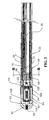
- FIGS. 1-6 illustrate a catheter system 20 according to one embodiment of the present invention.
- the catheter system 20 has a tubular shaft 22 having a distal end 26, a proximal end 28, and a main lumen 30 extending through the shaft 22.
- a distal tip section 24 is secured to the distal end 26 of the shaft 22.
- a handle assembly 32 is attached to the proximal end 28 of the shaft 22 using techniques that are well-known in the catheter art.
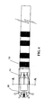
- the distal tip section 24 has an ablation element 60 that is housed inside a non-compliant and non-porous tubular cap 62.
- the ablation element 60 is spaced from, and does not contact, the walls of the cap 62.
- the cap 62 has a bore 64 extending therethrough.
- the distal end 26 of the shaft 22 is slide-fitted into the bore 64 at the proximal end 66 of the cap 62, and secured to the cap 62 by adhesive bonding.
- An inner sleeve 68 is secured by adhesive bonding in the main lumen 30 at the distal end 26 of the shaft 22.
- the inner sleeve 68 is made of a plastic material such as PEEK and has multiple channels 67 (see FIG.
- the cap 62 can be made from a non-compliant material such as polyethylene, polyurethane, polyolefins, polymethylpentene, and the like, that is capable of allowing ultrasound energy to be transmitted therethrough.
- the cap 62 extends from its proximal end 66 and terminates at a closed distal tip 92 that has an opening 94 provided thereat.
- the ablation element 60 is in the form of a transducer that includes a piezoelectric crystal which converts electrical energy into ultrasound energy.
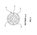
- the transducer 60 is tubular, and O-rings 108 are positioned between the transducer 60 and a tubular outer supporting member 104 to create an air space between the supporting member 104 and the transducer 60 to minimize transmission of ultrasound waves inside the transducer 60.
- a silicone adhesive 110 seals the ends of the transducer 60.
- Irrigation fluid fills the space between the transducer 60 and the cap 62, so that the ultrasound energy can be transmitted through the fluid and the cap 62 into the body tissue. The fluid acts to cool the transducer 60, and functions as a medium to transmit the ultrasound energy. Since the transducer 60 has a diameter that is smaller than the inner diameter of the cap 62, the transducer 60 does not contact the body tissue.
- An irrigation tube 100 extends through the main lumen 30 of the shaft 22, and has a distal end that terminates inside the proximal end 66 of the cap 62, at a location proximal to the transducer 60.
- Irrigation fluid is introduced from a pump 120 via a standard infusion tube 35 and a luer fitting 34 through the irrigation tube 100 to be delivered inside the bore 64 of the cap 62 for cooling the transducer 60.
- the inner supporting member 102 extends through the main lumen 30 of the shaft 22 and the bore 64 of the cap 62, terminating adjacent the opening 94 in the distal tip 92.
- the inner supporting member 102 functions to provide support to the catheter shaft 22 and the distal tip section 24, and is received inside the outer supporting member 104 that extends through the inner sleeve 68 and into the bore 64.
- the inner supporting member 102 can be provided in the form of a coil, a flat wire, or a rod composed of metal, alloy or a polymer.
- thermocouple wires 54 can have their distal tips secured to the inner surface of the cap 62, and are used to detect the temperature at the ablation site.
- a plurality of ring electrodes 58 are provided in spaced-apart manner about the outer surface of the shaft 22 adjacent the distal tip section 24.
- the ring electrodes 58 can be made of a solid, electrically conducting material, like platinum-iridium, stainless steel, or gold, that is attached about the shaft 22.
- the ring electrodes 58 can be formed by coating the exterior surface of the shaft 22 with an electrically conducting material, such as platinum-iridium or gold. The coating can be applied by sputtering, ion beam deposition or similar known techniques.
- the number of ring electrodes 58 can vary depending on the particular geometry of the region of use and the functionality desired.
- the ring electrodes 58 function to map the region of the heart that is to be treated. After the mapping has been completed, the transducer 60 is positioned at the location where ablation is to be performed, and the irrigation fluid through the lumen tube 100 is increased to the desired flow rate set on the pump 120. The flow of the irrigation fluid is software-controlled and its instructions are transmitted from the generator 52 to the pump 120 through the cable 45. The ablation is then carried out by energy that is emitted from the transducer 60 through the irrigation media (e.g., fluid, saline, contrast media or mixture) inside the cap 62.
- the irrigation media e.g., fluid, saline, contrast media or mixture
- a standard luer fitting 34 is connected to the proximal end of the tubing 38 extending out from the proximal end 36 of the handle assembly 32 using techniques that are well-known in the catheter art.
- the iuer fitting 34 provides a fluid line for irrigation media to be introduced to cool the transducer 60 at the distal tip section 24 of the shaft 22.
- the irrigation media is delivered via the infusion tube 35 and into the irrigation tube 100 that extends from the luer fitting 34, and terminates in the bore 64 of the cap 62.
- the irrigation media exits from the holes 98 located distally of the transducer 60 at the distal end of the cap 62.
- the cap 62 is completely closed without the distally located holes 98, and the irrigation media entering the bore 64 is withdrawn back out through another lumen tube (not shown) towards the proximal end of the catheter.
- a connector assembly 40 is also connected to the proximal end 36 of the handle assembly 32 using techniques that are well-known in the catheter art.
- the connector assembly 40 has a proximal connector 42 that couples the handle assembly 32 to the connector 44 of a cable 46 that leads to an ultrasound generator 52.
- An EP monitoring system 50 is coupled to the ultrasound generator 52 via another cable 48.
- the EP monitoring system 50 can be a conventional EP monitor which receives (via the ultrasound generator 52) electrical signals detected by the electrodes 58, and processes and displays these intracardiac signals to assist the physician in locating the arrhythmogenic sites or pathways.
- the ultrasound generator 52 can be a conventional ultrasound generator that creates and transmits ablating energy to the transducer 60, which emits the acoustic energy to ablate the tissue that extends radially from the position of the cap 62.
- Conductor wires 51 extend from the ultrasound generator 52 along the cables 46 and 48 (through the connector assembly 40, the handle assembly 32 and the lumen 30 of the shaft 22) to the distal tip section 24, where the conductor wires 51 couple the ring electrodes 58.
- the thermocouple wires 54 couple the cap 62, and the ultrasound wires 55 couple the transducer 60.
- the thermocouple wires 54 and ultrasound wires 55 can extend from the cap 62 and transducer 60 through the channels 67 of the inner sleeve 68 and through the lumen 30 of the shaft 22 and the handle assembly 32 to the proximal connector 42, where they can be electrically coupled by the internal thermocouple wires in the cable 46 to the ultrasound generator 52 where the temperature can be displayed.
- the handle assembly 32 also includes a steering mechanism 70 that functions to deflect the distal tip section 24 of the shaft 22 for maneuvering and positioning the distal tip section 24 at the desired location in the heart.
- the steering mechanism 70 includes a steering wire 72 that extends in the main lumen 30 of the shaft 22 from its proximal end at the handle assembly 32 to its distal end which terminates at the distal end 26 of the shaft 22 before the location of the distal tip section 24.
- the distal end of the steering wire 72 is secured to a flat wire 75 that is fixedly positioned inside the handle assembly 32.
- the flat wire 75 extends in the lumen 30 from the anchor to its distal end at a location slightly proximal to the inner sleeve 68.
- the flat wire 75 is attached to the steering wire 72 at the distal ends of the flat wire 75 and the steering wire 72 so as to be controlled by the steering wire 72. Specifically, by pushing the steering mechanism 70 forward in a distal direction, the steering mechanism 70 will pull the steering wire 72 in a proximal direction, causing the distal tip section 24 to deflect to one direction. By pulling back the steering mechanism 70 in a proximal direction, the steering wire 72 is deactivated and the distal tip section 24 returns to its neutral position or deflects to the opposite direction for bi-directionality.
- the physician uses a conventional introducer sheath to establish access to a selected artery or vein.
- the physician introduces the shaft 22 through a conventional hemostasis valve on the introducer and progressively advances the catheter through the access vein or artery into the desired location within the heart.
- the physician observes the progress of the catheter using fluoroscopic or ultrasound imaging.
- the catheter can include a radio-opaque compound, such as barium sulfate, for this purpose.
- radio-opaque markers can be placed at the distal end of the introducer sheath.
- the shaft 22 and the introducer sheath can be maneuvered to the right atrium by the steering mechanism 70. Once located in the right atrium or ventricle, good contact is established when the ring electrodes 58 contact the target endocardial tissue, and the intracardiac signals of the selected region are recorded through the ring electrodes 58.
- the results of the mapping operation are processed and displayed at the EP monitoring system 50.
- a differential input amplifier (not shown) in the EP monitoring system 50 processes the electrical signals received from the ring electrodes 58 via the wires 51, and converts them to graphic images that can be displayed.
- the thermocouple wires 54 can also function to monitor the temperature of the surrounding tissue, and provide temperature information to the ultrasound generator 52.
- the physician can then increase the irrigation fluid flow rate by turning the power of the ultrasound generator 52 on which controls the fluid flow rate prior to the start of ablation.
- the ultrasound generator 52 delivers high frequency energy that is propagated through the wires 55 to the ultrasound transducer 60 that is positioned inside the cap 62.
- the acoustic energy radiates in a radial manner from the transducer 60, propagates through the irrigation media (which acts as an energy transmitting medium), exits the cap 62 and then reaches the selected tissue (typically in a pressure waveform) to ablate the tissue.
Landscapes
- Health & Medical Sciences (AREA)
- Life Sciences & Earth Sciences (AREA)
- Engineering & Computer Science (AREA)
- Animal Behavior & Ethology (AREA)
- Veterinary Medicine (AREA)
- Public Health (AREA)
- General Health & Medical Sciences (AREA)
- Surgery (AREA)
- Biomedical Technology (AREA)
- Nuclear Medicine, Radiotherapy & Molecular Imaging (AREA)
- Medical Informatics (AREA)
- Molecular Biology (AREA)
- Heart & Thoracic Surgery (AREA)
- Vascular Medicine (AREA)
- Orthopedic Medicine & Surgery (AREA)
- Mechanical Engineering (AREA)
- Radiology & Medical Imaging (AREA)
- Physics & Mathematics (AREA)
- Biophysics (AREA)
- Pathology (AREA)
- Surgical Instruments (AREA)
Applications Claiming Priority (2)
| Application Number | Priority Date | Filing Date | Title |
|---|---|---|---|
| US845798 | 1997-04-25 | ||
| US10/845,798 US7285116B2 (en) | 2004-05-15 | 2004-05-15 | Non-contact tissue ablation device and methods thereof |
Publications (2)
| Publication Number | Publication Date |
|---|---|
| EP1595576A1 EP1595576A1 (en) | 2005-11-16 |
| EP1595576B1 true EP1595576B1 (en) | 2012-10-03 |
Family
ID=34936340
Family Applications (1)
| Application Number | Title | Priority Date | Filing Date |
|---|---|---|---|
| EP05010138A Ceased EP1595576B1 (en) | 2004-05-15 | 2005-05-10 | Non-contact tissue ablation device |
Country Status (5)
| Country | Link |
|---|---|
| US (2) | US7285116B2 (enExample) |
| EP (1) | EP1595576B1 (enExample) |
| JP (1) | JP4588528B2 (enExample) |
| CN (1) | CN100531679C (enExample) |
| CA (1) | CA2506921C (enExample) |
Families Citing this family (123)
| Publication number | Priority date | Publication date | Assignee | Title |
|---|---|---|---|---|
| US8974446B2 (en) * | 2001-10-11 | 2015-03-10 | St. Jude Medical, Inc. | Ultrasound ablation apparatus with discrete staggered ablation zones |
| US20070038056A1 (en) * | 2001-10-11 | 2007-02-15 | Carlo Pappone | System and methods for locating and ablating arrhythomogenic tissues |
| US6878147B2 (en) | 2001-11-02 | 2005-04-12 | Vivant Medical, Inc. | High-strength microwave antenna assemblies |
| US7128739B2 (en) | 2001-11-02 | 2006-10-31 | Vivant Medical, Inc. | High-strength microwave antenna assemblies and methods of use |
| US20040082859A1 (en) | 2002-07-01 | 2004-04-29 | Alan Schaer | Method and apparatus employing ultrasound energy to treat body sphincters |
| US7311703B2 (en) | 2003-07-18 | 2007-12-25 | Vivant Medical, Inc. | Devices and methods for cooling microwave antennas |
| WO2006031541A1 (en) * | 2004-09-09 | 2006-03-23 | Vnus Medical Technologies, Inc. | Methods and apparatus for treatment of hollow anatomical structures |
| US7799019B2 (en) | 2005-05-10 | 2010-09-21 | Vivant Medical, Inc. | Reinforced high strength microwave antenna |
| AU2006326909B2 (en) * | 2005-12-23 | 2012-08-16 | Cathrx Ltd | Irrigation catheter |
| US7950397B2 (en) | 2006-05-12 | 2011-05-31 | Vytronus, Inc. | Method for ablating body tissue |
| EP2021846B1 (en) | 2006-05-19 | 2017-05-03 | Koninklijke Philips N.V. | Ablation device with optimized input power profile |
| JP4933911B2 (ja) * | 2007-02-02 | 2012-05-16 | 学校法人日本医科大学 | 超音波手術器 |
| US7998139B2 (en) | 2007-04-25 | 2011-08-16 | Vivant Medical, Inc. | Cooled helical antenna for microwave ablation |
| US8721553B2 (en) * | 2007-05-15 | 2014-05-13 | General Electric Company | Fluid-fillable ultrasound imaging catheter tips |
| US8353901B2 (en) | 2007-05-22 | 2013-01-15 | Vivant Medical, Inc. | Energy delivery conduits for use with electrosurgical devices |
| US9023024B2 (en) | 2007-06-20 | 2015-05-05 | Covidien Lp | Reflective power monitoring for microwave applications |
| US8292880B2 (en) | 2007-11-27 | 2012-10-23 | Vivant Medical, Inc. | Targeted cooling of deployable microwave antenna |
| US9155588B2 (en) | 2008-06-13 | 2015-10-13 | Vytronus, Inc. | System and method for positioning an elongate member with respect to an anatomical structure |
| US20100049099A1 (en) * | 2008-07-18 | 2010-02-25 | Vytronus, Inc. | Method and system for positioning an energy source |
| US10363057B2 (en) * | 2008-07-18 | 2019-07-30 | Vytronus, Inc. | System and method for delivering energy to tissue |
| US20100057073A1 (en) * | 2008-09-02 | 2010-03-04 | Medtronc, Inc. | Irrigated Ablation Catheter System and Methods |
| US9192789B2 (en) | 2008-10-30 | 2015-11-24 | Vytronus, Inc. | System and method for anatomical mapping of tissue and planning ablation paths therein |
| US8414508B2 (en) | 2008-10-30 | 2013-04-09 | Vytronus, Inc. | System and method for delivery of energy to tissue while compensating for collateral tissue |
| US9220924B2 (en) | 2008-10-30 | 2015-12-29 | Vytronus, Inc. | System and method for energy delivery to tissue while monitoring position, lesion depth, and wall motion |
| US11298568B2 (en) | 2008-10-30 | 2022-04-12 | Auris Health, Inc. | System and method for energy delivery to tissue while monitoring position, lesion depth, and wall motion |
| US9033885B2 (en) * | 2008-10-30 | 2015-05-19 | Vytronus, Inc. | System and method for energy delivery to tissue while monitoring position, lesion depth, and wall motion |
| US9795442B2 (en) | 2008-11-11 | 2017-10-24 | Shifamed Holdings, Llc | Ablation catheters |
| CA2742787C (en) | 2008-11-17 | 2018-05-15 | Vytronus, Inc. | Systems and methods for ablating body tissue |
| US8475379B2 (en) | 2008-11-17 | 2013-07-02 | Vytronus, Inc. | Systems and methods for ablating body tissue |
| US9629678B2 (en) * | 2008-12-30 | 2017-04-25 | St. Jude Medical, Atrial Fibrillation Division, Inc. | Controlled irrigated catheter ablation systems and methods thereof |
| EP2376011B1 (en) | 2009-01-09 | 2019-07-03 | ReCor Medical, Inc. | Apparatus for treatment of mitral valve insufficiency |
| US9936892B1 (en) | 2009-05-04 | 2018-04-10 | Cortex Manufacturing Inc. | Systems and methods for providing a fiducial marker |
| US9277961B2 (en) | 2009-06-12 | 2016-03-08 | Advanced Cardiac Therapeutics, Inc. | Systems and methods of radiometrically determining a hot-spot temperature of tissue being treated |
| US8926605B2 (en) | 2012-02-07 | 2015-01-06 | Advanced Cardiac Therapeutics, Inc. | Systems and methods for radiometrically measuring temperature during tissue ablation |
| US8954161B2 (en) | 2012-06-01 | 2015-02-10 | Advanced Cardiac Therapeutics, Inc. | Systems and methods for radiometrically measuring temperature and detecting tissue contact prior to and during tissue ablation |
| US9226791B2 (en) | 2012-03-12 | 2016-01-05 | Advanced Cardiac Therapeutics, Inc. | Systems for temperature-controlled ablation using radiometric feedback |
| US8355803B2 (en) | 2009-09-16 | 2013-01-15 | Vivant Medical, Inc. | Perfused core dielectrically loaded dipole microwave antenna probe |
| WO2011053757A1 (en) | 2009-10-30 | 2011-05-05 | Sound Interventions, Inc. | Method and apparatus for treatment of hypertension through percutaneous ultrasound renal denervation |
| US8469953B2 (en) | 2009-11-16 | 2013-06-25 | Covidien Lp | Twin sealing chamber hub |
| JP5603054B2 (ja) * | 2009-11-27 | 2014-10-08 | 株式会社ナカニシ | 振動子カバー |
| US20110137284A1 (en) * | 2009-12-03 | 2011-06-09 | Northwestern University | Devices for material delivery, electroporation, and monitoring electrophysiological activity |
| US20110201973A1 (en) * | 2010-02-18 | 2011-08-18 | St. Jude Medical, Inc. | Ultrasound compatible radiofrequency ablation electrode |
| US9655677B2 (en) | 2010-05-12 | 2017-05-23 | Shifamed Holdings, Llc | Ablation catheters including a balloon and electrodes |
| CA2797130A1 (en) | 2010-05-12 | 2011-11-17 | Shifamed Holdings, Llc | Low profile electrode assembly |
| US8696581B2 (en) | 2010-10-18 | 2014-04-15 | CardioSonic Ltd. | Ultrasound transducer and uses thereof |
| EP2661304A1 (en) | 2010-10-18 | 2013-11-13 | Cardiosonic Ltd. | Therapeutics reservoir |
| US9028417B2 (en) | 2010-10-18 | 2015-05-12 | CardioSonic Ltd. | Ultrasound emission element |
| US9566456B2 (en) * | 2010-10-18 | 2017-02-14 | CardioSonic Ltd. | Ultrasound transceiver and cooling thereof |
| TWI556849B (zh) | 2010-10-21 | 2016-11-11 | 美敦力阿福盧森堡公司 | 用於腎臟神經協調的導管裝置 |
| MX2013004235A (es) | 2010-10-25 | 2013-05-30 | Medtronic Ardian Luxembourg | Aparatos de cateter que tienen arreglos de multiples electrodos para neuromodulacion renal y sistemas y metodos asociados. |
| US9220433B2 (en) | 2011-06-30 | 2015-12-29 | Biosense Webster (Israel), Ltd. | Catheter with variable arcuate distal section |
| US9662169B2 (en) | 2011-07-30 | 2017-05-30 | Biosense Webster (Israel) Ltd. | Catheter with flow balancing valve |
| JP2012035101A (ja) * | 2011-10-17 | 2012-02-23 | Nippon Medical School | 超音波手術器 |
| WO2013142906A1 (en) * | 2012-03-27 | 2013-10-03 | Cathrx Ltd | An ablation catheter |
| WO2013157011A2 (en) | 2012-04-18 | 2013-10-24 | CardioSonic Ltd. | Tissue treatment |
| AU2013260174B2 (en) | 2012-05-11 | 2016-01-07 | Medtronic Af Luxembourg S.A.R.L. | Multi-electrode catheter assemblies for renal neuromodulation and associated systems and methods |
| KR101415902B1 (ko) * | 2012-05-18 | 2014-07-08 | 신경민 | 소작 겸용 스텐트 시술장치 |
| US11357447B2 (en) | 2012-05-31 | 2022-06-14 | Sonivie Ltd. | Method and/or apparatus for measuring renal denervation effectiveness |
| US9044254B2 (en) | 2012-08-07 | 2015-06-02 | Covidien Lp | Microwave ablation catheter and method of utilizing the same |
| JP6301926B2 (ja) | 2012-08-09 | 2018-03-28 | ユニバーシティ オブ アイオワ リサーチ ファウンデーション | カテーテル、カテーテルシステム、及び組織構造を刺通する方法 |
| US9044575B2 (en) | 2012-10-22 | 2015-06-02 | Medtronic Adrian Luxembourg S.a.r.l. | Catheters with enhanced flexibility and associated devices, systems, and methods |
| JP6322696B2 (ja) | 2013-03-14 | 2018-05-09 | リコール メディカル インコーポレイテッドReCor Medical, Inc. | 超音波による神経調節システム |
| WO2014159273A1 (en) | 2013-03-14 | 2014-10-02 | Recor Medical, Inc. | Methods of plating or coating ultrasound transducers |
| US20140276714A1 (en) * | 2013-03-15 | 2014-09-18 | Boston Scientific Scimed, Inc. | Active infusion sheath for ultrasound ablation catheter |
| EP2978382B1 (en) | 2013-03-29 | 2018-05-02 | Covidien LP | Step-down coaxial microwave ablation applicators and methods for manufacturing same |
| FR3004115B1 (fr) * | 2013-04-04 | 2016-05-06 | Nestis | Catheter d'injection de fluide a deux gaines coulissantes |
| HK1219401A1 (zh) | 2013-04-08 | 2017-04-07 | Apama Medical, Inc. | 心臟消融導管及其使用方法 |
| US10349824B2 (en) | 2013-04-08 | 2019-07-16 | Apama Medical, Inc. | Tissue mapping and visualization systems |
| US10098694B2 (en) | 2013-04-08 | 2018-10-16 | Apama Medical, Inc. | Tissue ablation and monitoring thereof |
| WO2014189794A1 (en) | 2013-05-18 | 2014-11-27 | Medtronic Ardian Luxembourg S.A.R.L. | Neuromodulation catheters with shafts for enhanced flexibility and control and associated devices, systems, and methods |
| EP2999411B1 (en) | 2013-05-23 | 2020-10-07 | Cardiosonic Ltd. | Devices for renal denervation and assessment thereof |
| EP3071125B1 (en) * | 2013-11-18 | 2021-08-04 | Koninklijke Philips N.V. | Devices for thrombus dispersal |
| EP3091921B1 (en) | 2014-01-06 | 2019-06-19 | Farapulse, Inc. | Apparatus for renal denervation ablation |
| EP4253024B1 (en) | 2014-01-27 | 2025-02-26 | Medtronic Ireland Manufacturing Unlimited Company | Neuromodulation catheters having jacketed neuromodulation elements and related devices |
| EP4371512A3 (en) | 2014-04-24 | 2024-08-14 | Medtronic Ardian Luxembourg S.à.r.l. | Neuromodulation catheters having braided shafts and associated systems and methods |
| WO2015171921A2 (en) | 2014-05-07 | 2015-11-12 | Mickelson Steven R | Methods and apparatus for selective tissue ablation |
| WO2015175944A1 (en) | 2014-05-16 | 2015-11-19 | Gary Long | Methods and apparatus for multi-catheter tissue ablation |
| WO2015192027A1 (en) | 2014-06-12 | 2015-12-17 | Iowa Approach Inc. | Method and apparatus for rapid and selective transurethral tissue ablation |
| EP3154464B1 (en) | 2014-06-12 | 2025-03-12 | Boston Scientific Scimed, Inc. | Apparatus for rapid and selective tissue ablation with cooling |
| US10624697B2 (en) | 2014-08-26 | 2020-04-21 | Covidien Lp | Microwave ablation system |
| US10813691B2 (en) | 2014-10-01 | 2020-10-27 | Covidien Lp | Miniaturized microwave ablation assembly |
| EP3206613B1 (en) | 2014-10-14 | 2019-07-03 | Farapulse, Inc. | Apparatus for rapid and safe pulmonary vein cardiac ablation |
| CA2967829A1 (en) | 2014-11-19 | 2016-05-26 | Advanced Cardiac Therapeutics, Inc. | Systems and methods for high-resolution mapping of tissue |
| WO2016081611A1 (en) | 2014-11-19 | 2016-05-26 | Advanced Cardiac Therapeutics, Inc. | High-resolution mapping of tissue with pacing |
| CA2967824A1 (en) | 2014-11-19 | 2016-05-26 | Advanced Cardiac Therapeutics, Inc. | Ablation devices, systems and methods of using a high-resolution electrode assembly |
| US9636164B2 (en) | 2015-03-25 | 2017-05-02 | Advanced Cardiac Therapeutics, Inc. | Contact sensing systems and methods |
| US10656025B2 (en) | 2015-06-10 | 2020-05-19 | Ekos Corporation | Ultrasound catheter |
| EP3376936B1 (en) | 2015-11-16 | 2024-01-03 | Boston Scientific Scimed, Inc. | Energy delivery devices |
| US11160607B2 (en) * | 2015-11-20 | 2021-11-02 | Biosense Webster (Israel) Ltd. | Hyper-apertured ablation electrode |
| US12144541B2 (en) | 2016-01-05 | 2024-11-19 | Boston Scientific Scimed, Inc. | Systems, apparatuses and methods for delivery of ablative energy to tissue |
| US10130423B1 (en) | 2017-07-06 | 2018-11-20 | Farapulse, Inc. | Systems, devices, and methods for focal ablation |
| US20170189097A1 (en) | 2016-01-05 | 2017-07-06 | Iowa Approach Inc. | Systems, apparatuses and methods for delivery of ablative energy to tissue |
| US10660702B2 (en) | 2016-01-05 | 2020-05-26 | Farapulse, Inc. | Systems, devices, and methods for focal ablation |
| US10172673B2 (en) | 2016-01-05 | 2019-01-08 | Farapulse, Inc. | Systems devices, and methods for delivery of pulsed electric field ablative energy to endocardial tissue |
| US10813692B2 (en) | 2016-02-29 | 2020-10-27 | Covidien Lp | 90-degree interlocking geometry for introducer for facilitating deployment of microwave radiating catheter |
| KR20180124070A (ko) | 2016-03-15 | 2018-11-20 | 에픽스 테라퓨틱스, 인크. | 관개 절제를 위한 개선된 장치, 시스템 및 방법 |
| WO2017218734A1 (en) | 2016-06-16 | 2017-12-21 | Iowa Approach, Inc. | Systems, apparatuses, and methods for guide wire delivery |
| US11065053B2 (en) | 2016-08-02 | 2021-07-20 | Covidien Lp | Ablation cable assemblies and a method of manufacturing the same |
| US10376309B2 (en) | 2016-08-02 | 2019-08-13 | Covidien Lp | Ablation cable assemblies and a method of manufacturing the same |
| US11197715B2 (en) | 2016-08-02 | 2021-12-14 | Covidien Lp | Ablation cable assemblies and a method of manufacturing the same |
| US20200238107A1 (en) | 2017-03-20 | 2020-07-30 | Sonie Vie Ltd. | Pulmonary hypertension treatment method and/or system |
| EP3614946B1 (en) | 2017-04-27 | 2024-03-20 | EPiX Therapeutics, Inc. | Determining nature of contact between catheter tip and tissue |
| US9987081B1 (en) | 2017-04-27 | 2018-06-05 | Iowa Approach, Inc. | Systems, devices, and methods for signal generation |
| US10617867B2 (en) | 2017-04-28 | 2020-04-14 | Farapulse, Inc. | Systems, devices, and methods for delivery of pulsed electric field ablative energy to esophageal tissue |
| CN115844523A (zh) | 2017-09-12 | 2023-03-28 | 波士顿科学医学有限公司 | 用于心室局灶性消融的系统、设备和方法 |
| EP4275738B1 (en) | 2018-02-08 | 2025-12-17 | Boston Scientific Scimed, Inc. | Apparatus for controlled delivery of pulsed electric field ablative energy to tissue |
| US20190336198A1 (en) | 2018-05-03 | 2019-11-07 | Farapulse, Inc. | Systems, devices, and methods for ablation using surgical clamps |
| WO2019217433A1 (en) | 2018-05-07 | 2019-11-14 | Farapulse, Inc. | Systems, apparatuses and methods for delivery of ablative energy to tissue |
| CN112087978B (zh) | 2018-05-07 | 2023-01-17 | 波士顿科学医学有限公司 | 心外膜消融导管 |
| EP3790483B1 (en) | 2018-05-07 | 2024-08-28 | Boston Scientific Scimed, Inc. | Systems for filtering high voltage noise induced by pulsed electric field ablation |
| CN112955088B (zh) | 2018-09-20 | 2024-11-26 | 波士顿科学医学有限公司 | 用于将脉冲电场消融能量输送到心内膜组织的系统、装置和方法 |
| WO2020123797A1 (en) * | 2018-12-14 | 2020-06-18 | Teitelbaum George P | Vagus nerve ablation devices, systems, and methods |
| US10625080B1 (en) | 2019-09-17 | 2020-04-21 | Farapulse, Inc. | Systems, apparatuses, and methods for detecting ectopic electrocardiogram signals during pulsed electric field ablation |
| US11497541B2 (en) | 2019-11-20 | 2022-11-15 | Boston Scientific Scimed, Inc. | Systems, apparatuses, and methods for protecting electronic components from high power noise induced by high voltage pulses |
| US11065047B2 (en) | 2019-11-20 | 2021-07-20 | Farapulse, Inc. | Systems, apparatuses, and methods for protecting electronic components from high power noise induced by high voltage pulses |
| US10842572B1 (en) | 2019-11-25 | 2020-11-24 | Farapulse, Inc. | Methods, systems, and apparatuses for tracking ablation devices and generating lesion lines |
| US12310652B2 (en) | 2020-07-24 | 2025-05-27 | Boston Scientific Scimed, Inc. | Hybrid electroporation ablation catheter |
| WO2022020478A1 (en) | 2020-07-24 | 2022-01-27 | Boston Scientific Scimed Inc | Electric field application for single shot cardiac ablation by irreversible electroporation |
| JP7617250B2 (ja) | 2020-09-08 | 2025-01-17 | ボストン サイエンティフィック サイムド,インコーポレイテッド | パルス電界アブレーションのための輪郭成形電極、ならびにそのシステム、デバイス、および方法 |
| US12349964B2 (en) | 2020-09-30 | 2025-07-08 | Boston Scientific Scimed, Inc. | Pretreatment waveform for irreversible electroporation |
| CN116744870A (zh) | 2021-01-27 | 2023-09-12 | 波士顿科学医学有限公司 | 用于不可逆电穿孔消融的电压控制的脉冲序列 |
| CN112807058B (zh) * | 2021-02-03 | 2022-05-17 | 清华大学 | 介入式超声溶栓装置 |
| WO2025108651A1 (en) * | 2023-11-20 | 2025-05-30 | Vascomed Gmbh | Manufacturing method for a catheter assembly |
Family Cites Families (38)
| Publication number | Priority date | Publication date | Assignee | Title |
|---|---|---|---|---|
| US624166A (en) * | 1899-05-02 | William hadfield bowers | ||
| US5295484A (en) * | 1992-05-19 | 1994-03-22 | Arizona Board Of Regents For And On Behalf Of The University Of Arizona | Apparatus and method for intra-cardiac ablation of arrhythmias |
| US5676693A (en) * | 1992-11-13 | 1997-10-14 | Scimed Life Systems, Inc. | Electrophysiology device |
| US5620479A (en) * | 1992-11-13 | 1997-04-15 | The Regents Of The University Of California | Method and apparatus for thermal therapy of tumors |
| US5348554A (en) | 1992-12-01 | 1994-09-20 | Cardiac Pathways Corporation | Catheter for RF ablation with cooled electrode |
| US5545161A (en) * | 1992-12-01 | 1996-08-13 | Cardiac Pathways Corporation | Catheter for RF ablation having cooled electrode with electrically insulated sleeve |
| US6161543A (en) * | 1993-02-22 | 2000-12-19 | Epicor, Inc. | Methods of epicardial ablation for creating a lesion around the pulmonary veins |
| US5630837A (en) | 1993-07-01 | 1997-05-20 | Boston Scientific Corporation | Acoustic ablation |
| JP3898754B2 (ja) * | 1993-07-01 | 2007-03-28 | ボストン サイエンティフィック リミテッド | 像形成、電位検出型及び切除カテーテル |
| US5921982A (en) * | 1993-07-30 | 1999-07-13 | Lesh; Michael D. | Systems and methods for ablating body tissue |
| DE19504261A1 (de) * | 1995-02-09 | 1996-09-12 | Krieg Gunther | Angioplastie-Katheter zum Erweitern und/oder Eröffnen von Blutgefäßen |
| CA2222617C (en) * | 1995-05-02 | 2002-07-16 | Heart Rhythm Technologies, Inc. | System for controlling the energy delivered to a patient for ablation |
| US5735811A (en) * | 1995-11-30 | 1998-04-07 | Pharmasonics, Inc. | Apparatus and methods for ultrasonically enhanced fluid delivery |
| JP4018147B2 (ja) * | 1996-05-17 | 2007-12-05 | バイオセンス・インコーポレイテッド | 自己位置合せカテーテル |
| US5846218A (en) * | 1996-09-05 | 1998-12-08 | Pharmasonics, Inc. | Balloon catheters having ultrasonically driven interface surfaces and methods for their use |
| JPH10127678A (ja) * | 1996-10-31 | 1998-05-19 | Olympus Optical Co Ltd | 超音波診断治療装置 |
| US5971983A (en) * | 1997-05-09 | 1999-10-26 | The Regents Of The University Of California | Tissue ablation device and method of use |
| US6012457A (en) | 1997-07-08 | 2000-01-11 | The Regents Of The University Of California | Device and method for forming a circumferential conduction block in a pulmonary vein |
| US5997532A (en) * | 1997-07-03 | 1999-12-07 | Cardiac Pathways Corporation | Ablation catheter tip with a buffer layer covering the electrode |
| US6241666B1 (en) * | 1997-07-03 | 2001-06-05 | Cardiac Pathways Corp. | Ablation catheter tip with a buffer layer covering the electrode |
| US6245064B1 (en) | 1997-07-08 | 2001-06-12 | Atrionix, Inc. | Circumferential ablation device assembly |
| US6164283A (en) | 1997-07-08 | 2000-12-26 | The Regents Of The University Of California | Device and method for forming a circumferential conduction block in a pulmonary vein |
| US6080151A (en) * | 1997-07-21 | 2000-06-27 | Daig Corporation | Ablation catheter |
| US6579288B1 (en) * | 1997-10-10 | 2003-06-17 | Scimed Life Systems, Inc. | Fluid cooled apparatus for supporting diagnostic and therapeutic elements in contact with tissue |
| US6120476A (en) | 1997-12-01 | 2000-09-19 | Cordis Webster, Inc. | Irrigated tip catheter |
| US6241727B1 (en) * | 1998-05-27 | 2001-06-05 | Irvine Biomedical, Inc. | Ablation catheter system having circular lesion capabilities |
| US6315777B1 (en) * | 1998-07-07 | 2001-11-13 | Medtronic, Inc. | Method and apparatus for creating a virtual electrode used for the ablation of tissue |
| US6206842B1 (en) * | 1998-08-03 | 2001-03-27 | Lily Chen Tu | Ultrasonic operation device |
| US6206831B1 (en) * | 1999-01-06 | 2001-03-27 | Scimed Life Systems, Inc. | Ultrasound-guided ablation catheter and methods of use |
| US6524251B2 (en) * | 1999-10-05 | 2003-02-25 | Omnisonics Medical Technologies, Inc. | Ultrasonic device for tissue ablation and sheath for use therewith |
| US6942661B2 (en) * | 2000-08-30 | 2005-09-13 | Boston Scientific Scimed, Inc. | Fluid cooled apparatus for supporting diagnostic and therapeutic elements in contact with tissue |
| US6672312B2 (en) * | 2001-01-31 | 2004-01-06 | Transurgical, Inc. | Pulmonary vein ablation with myocardial tissue locating |
| US6671533B2 (en) * | 2001-10-11 | 2003-12-30 | Irvine Biomedical Inc. | System and method for mapping and ablating body tissue of the interior region of the heart |
| ATE333923T1 (de) * | 2001-12-03 | 2006-08-15 | Ekos Corp | Ultraschallkatheter für kleine gefässe |
| US6866662B2 (en) * | 2002-07-23 | 2005-03-15 | Biosense Webster, Inc. | Ablation catheter having stabilizing array |
| US7137963B2 (en) * | 2002-08-26 | 2006-11-21 | Flowcardia, Inc. | Ultrasound catheter for disrupting blood vessel obstructions |
| US6921371B2 (en) * | 2002-10-14 | 2005-07-26 | Ekos Corporation | Ultrasound radiating members for catheter |
| US7247141B2 (en) * | 2004-03-08 | 2007-07-24 | Ethicon Endo-Surgery, Inc. | Intra-cavitary ultrasound medical system and method |
-
2004
- 2004-05-15 US US10/845,798 patent/US7285116B2/en not_active Expired - Fee Related
-
2005
- 2005-05-09 CA CA2506921A patent/CA2506921C/en not_active Expired - Fee Related
- 2005-05-10 EP EP05010138A patent/EP1595576B1/en not_active Ceased
- 2005-05-12 JP JP2005139468A patent/JP4588528B2/ja not_active Expired - Fee Related
- 2005-05-16 CN CNB2005100726584A patent/CN100531679C/zh not_active Expired - Fee Related
-
2007
- 2007-10-22 US US11/975,822 patent/US20080177205A1/en not_active Abandoned
Also Published As
| Publication number | Publication date |
|---|---|
| US20080177205A1 (en) | 2008-07-24 |
| CA2506921A1 (en) | 2005-11-15 |
| EP1595576A1 (en) | 2005-11-16 |
| CN1720874A (zh) | 2006-01-18 |
| JP2005324029A (ja) | 2005-11-24 |
| CA2506921C (en) | 2013-01-08 |
| US20050256518A1 (en) | 2005-11-17 |
| CN100531679C (zh) | 2009-08-26 |
| JP4588528B2 (ja) | 2010-12-01 |
| US7285116B2 (en) | 2007-10-23 |
Similar Documents
| Publication | Publication Date | Title |
|---|---|---|
| EP1595576B1 (en) | Non-contact tissue ablation device | |
| US6217576B1 (en) | Catheter probe for treating focal atrial fibrillation in pulmonary veins | |
| US6241726B1 (en) | Catheter system having a tip section with fixation means | |
| US6156031A (en) | Transmyocardial revascularization using radiofrequency energy | |
| EP0975271B1 (en) | Cardiac tissue ablation device | |
| US5971968A (en) | Catheter probe having contrast media delivery means | |
| US5792140A (en) | Catheter having cooled multiple-needle electrode | |
| US5891137A (en) | Catheter system having a tip with fixation means | |
| EP1450664B1 (en) | System for mapping and ablating body tissue of the interior region of the heart | |
| US5941845A (en) | Catheter having multiple-needle electrode and methods thereof | |
| US5897554A (en) | Steerable catheter having a loop electrode | |
| US6033403A (en) | Long electrode catheter system and methods thereof | |
| CN104427950B (zh) | 用于治疗心房扑动的具有单动作双偏转机构的导管 | |
| US8974446B2 (en) | Ultrasound ablation apparatus with discrete staggered ablation zones | |
| AU2010315625B2 (en) | Methods and systems for ablating tissue | |
| JP4873816B2 (ja) | ガイドワイヤトラッキング機構を備えた先端部可撓性カテーテル | |
| CA2305333A1 (en) | Transmyocardial revascularization using radiofrequency energy | |
| CN120112234A (zh) | 超声成像消融导管系统及方法 |
Legal Events
| Date | Code | Title | Description |
|---|---|---|---|
| PUAI | Public reference made under article 153(3) epc to a published international application that has entered the european phase |
Free format text: ORIGINAL CODE: 0009012 |
|
| AK | Designated contracting states |
Kind code of ref document: A1 Designated state(s): AT BE BG CH CY CZ DE DK EE ES FI FR GB GR HU IE IS IT LI LT LU MC NL PL PT RO SE SI SK TR |
|
| AX | Request for extension of the european patent |
Extension state: AL BA HR LV MK YU |
|
| 17P | Request for examination filed |
Effective date: 20060502 |
|
| AKX | Designation fees paid |
Designated state(s): DE FR GB |
|
| 17Q | First examination report despatched |
Effective date: 20081106 |
|
| GRAJ | Information related to disapproval of communication of intention to grant by the applicant or resumption of examination proceedings by the epo deleted |
Free format text: ORIGINAL CODE: EPIDOSDIGR1 |
|
| GRAP | Despatch of communication of intention to grant a patent |
Free format text: ORIGINAL CODE: EPIDOSNIGR1 |
|
| GRAS | Grant fee paid |
Free format text: ORIGINAL CODE: EPIDOSNIGR3 |
|
| GRAA | (expected) grant |
Free format text: ORIGINAL CODE: 0009210 |
|
| AK | Designated contracting states |
Kind code of ref document: B1 Designated state(s): DE FR GB |
|
| REG | Reference to a national code |
Ref country code: GB Ref legal event code: FG4D |
|
| REG | Reference to a national code |
Ref country code: DE Ref legal event code: R096 Ref document number: 602005036348 Country of ref document: DE Effective date: 20121129 |
|
| PLBE | No opposition filed within time limit |
Free format text: ORIGINAL CODE: 0009261 |
|
| STAA | Information on the status of an ep patent application or granted ep patent |
Free format text: STATUS: NO OPPOSITION FILED WITHIN TIME LIMIT |
|
| 26N | No opposition filed |
Effective date: 20130704 |
|
| REG | Reference to a national code |
Ref country code: DE Ref legal event code: R097 Ref document number: 602005036348 Country of ref document: DE Effective date: 20130704 |
|
| REG | Reference to a national code |
Ref country code: FR Ref legal event code: PLFP Year of fee payment: 11 |
|
| REG | Reference to a national code |
Ref country code: FR Ref legal event code: PLFP Year of fee payment: 12 |
|
| REG | Reference to a national code |
Ref country code: FR Ref legal event code: PLFP Year of fee payment: 13 |
|
| REG | Reference to a national code |
Ref country code: FR Ref legal event code: PLFP Year of fee payment: 14 |
|
| PGFP | Annual fee paid to national office [announced via postgrant information from national office to epo] |
Ref country code: DE Payment date: 20180529 Year of fee payment: 14 |
|
| PGFP | Annual fee paid to national office [announced via postgrant information from national office to epo] |
Ref country code: FR Payment date: 20180525 Year of fee payment: 14 |
|
| PGFP | Annual fee paid to national office [announced via postgrant information from national office to epo] |
Ref country code: GB Payment date: 20180529 Year of fee payment: 14 |
|
| REG | Reference to a national code |
Ref country code: DE Ref legal event code: R119 Ref document number: 602005036348 Country of ref document: DE |
|
| GBPC | Gb: european patent ceased through non-payment of renewal fee |
Effective date: 20190510 |
|
| PG25 | Lapsed in a contracting state [announced via postgrant information from national office to epo] |
Ref country code: DE Free format text: LAPSE BECAUSE OF NON-PAYMENT OF DUE FEES Effective date: 20191203 Ref country code: GB Free format text: LAPSE BECAUSE OF NON-PAYMENT OF DUE FEES Effective date: 20190510 |
|
| PG25 | Lapsed in a contracting state [announced via postgrant information from national office to epo] |
Ref country code: FR Free format text: LAPSE BECAUSE OF NON-PAYMENT OF DUE FEES Effective date: 20190531 |