EP1594343A2 - Hörhilfevorrichtung und entsprechendes Betriebsverfahren - Google Patents
Hörhilfevorrichtung und entsprechendes Betriebsverfahren Download PDFInfo
- Publication number
- EP1594343A2 EP1594343A2 EP05103360A EP05103360A EP1594343A2 EP 1594343 A2 EP1594343 A2 EP 1594343A2 EP 05103360 A EP05103360 A EP 05103360A EP 05103360 A EP05103360 A EP 05103360A EP 1594343 A2 EP1594343 A2 EP 1594343A2
- Authority
- EP
- European Patent Office
- Prior art keywords
- hearing aid
- directional microphone
- mode
- signals
- aid device
- Prior art date
- Legal status (The legal status is an assumption and is not a legal conclusion. Google has not performed a legal analysis and makes no representation as to the accuracy of the status listed.)
- Granted
Links
Images

Classifications
-
- H—ELECTRICITY
- H04—ELECTRIC COMMUNICATION TECHNIQUE
- H04R—LOUDSPEAKERS, MICROPHONES, GRAMOPHONE PICK-UPS OR LIKE ACOUSTIC ELECTROMECHANICAL TRANSDUCERS; ELECTRIC HEARING AIDS; PUBLIC ADDRESS SYSTEMS
- H04R25/00—Electric hearing aids
- H04R25/55—Electric hearing aids using an external connection, either wireless or wired
- H04R25/554—Electric hearing aids using an external connection, either wireless or wired using a wireless connection, e.g. between microphone and amplifier or using Tcoils
-
- H—ELECTRICITY
- H04—ELECTRIC COMMUNICATION TECHNIQUE
- H04R—LOUDSPEAKERS, MICROPHONES, GRAMOPHONE PICK-UPS OR LIKE ACOUSTIC ELECTROMECHANICAL TRANSDUCERS; ELECTRIC HEARING AIDS; PUBLIC ADDRESS SYSTEMS
- H04R25/00—Electric hearing aids
- H04R25/40—Arrangements for obtaining a desired directivity characteristic
- H04R25/405—Arrangements for obtaining a desired directivity characteristic by combining a plurality of transducers
-
- H—ELECTRICITY
- H04—ELECTRIC COMMUNICATION TECHNIQUE
- H04R—LOUDSPEAKERS, MICROPHONES, GRAMOPHONE PICK-UPS OR LIKE ACOUSTIC ELECTROMECHANICAL TRANSDUCERS; ELECTRIC HEARING AIDS; PUBLIC ADDRESS SYSTEMS
- H04R2225/00—Details of deaf aids covered by H04R25/00, not provided for in any of its subgroups
- H04R2225/61—Aspects relating to mechanical or electronic switches or control elements, e.g. functioning
-
- H—ELECTRICITY
- H04—ELECTRIC COMMUNICATION TECHNIQUE
- H04R—LOUDSPEAKERS, MICROPHONES, GRAMOPHONE PICK-UPS OR LIKE ACOUSTIC ELECTROMECHANICAL TRANSDUCERS; ELECTRIC HEARING AIDS; PUBLIC ADDRESS SYSTEMS
- H04R25/00—Electric hearing aids
- H04R25/60—Mounting or interconnection of hearing aid parts, e.g. inside tips, housings or to ossicles
- H04R25/603—Mounting or interconnection of hearing aid parts, e.g. inside tips, housings or to ossicles of mechanical or electronic switches or control elements
Definitions
- the present invention relates to a hearing aid device with a housing, a directional microphone device, a Transmission device for electrical or electromagnetic Transmitting signals between the hearing aid device and an external device and a hearing aid device for amplifying directional microphone signals exclusively come directly from the directional microphone device, in a first mode of operation and for amplifying signals, which originate from the transmission device, in one second operating mode.
- the present concerns Invention a corresponding method for operating a Hearing aid.
- in-the-ear hearing aids with the help of a Otoplasty inserted into the ear canal.
- the microphones of the Directional microphones of the hearing aid are arranged so that its highest sensitivity in the inserted state of the Hearing aid substantially horizontally facing forward.
- headsets are available on the market, the used for example in conjunction with mobile phones become.
- the phone signal is wireless or wired from the phone to the headset. This is either by an earmold or with an earplug attached in the ear and partially covers the auricle.
- Headset would also have hearing aid functionality. This would have the advantage that the headset user also from one Frequency response shaping of a hearing aid could benefit.
- the problem here is that in a hearing aid mode the directional microphones horizontally forward and in one Phone mode to be directed to the mouth of the user would.
- the Actuator may be in the form of a microswitch as Push-button or rocker switch or in the form of a small Rotary switch be formed, in particular in the Training as a switch with rotatable actuator also several switching functions can be triggered or several switching positions are selectable.
- the patent DE 42 33 813 C1 a programmable hearing aid with space-saving arrangement the switch elements. It is in a programming socket Switching element for switching on / off the hearing aid used.
- the usable switch element can be used as a rotary switch or Potentiometer be formed.
- the object of the present invention is therefore to To specify a hearing aid, the problem Takes into account. In addition, a corresponding procedure for operating a hearing aid device.
- this object is achieved by a hearing aid device with a housing, a directional microphone device, a transmission device for electrical or electromagnetic Transmitting signals between the hearing aid device and an external device and a Hearing aid device for amplifying directional microphone signals, the exclusively directly from the directional microphone device come in a first mode of operation and to amplify Signals originating from the transmission device in one second operating mode, as well as a rotary switch, the one first and a rotatable second section, wherein the housing with the first and the directional microphone device connected to the second section, so that the hearing aid device by turning the directional microphone device relative to the housing from one to the other the two operating modes can be switched.
- the switching functionality coupled with the alignment process of directional microphones and thus a compromise to be avoided, according to which the directional microphones in a middle position between the horizontal and the direction of the user's mouth would be fixed.
- signals are also preferably amplified by the directional microphone device. This is not only necessarily with binaural supply, but also brings benefits for the hearing impaired, as their own language is strengthened for her suitably.
- the second operating mode may be a telephone mode wherein the electrically or electromagnetically transmitted signals come from a telephone.
- the easy switch to the phone mode will be a major application area, Nevertheless, the inventive method and the inventive Hearing aid device also suitable for that in the second mode only the own voice signals be transmitted to an external amplifier. This is suitable for example, for events in larger rooms, television events and the same.
- the Carrier in the second mode also from the hearing aid functionality benefit and possibly in the pure hearing aid operation switch over by simply turning the directional microphones.
- Hearing aid device has the transmission device Bluetooth chip on. This can be standard transmission methods be used.
- the rotary switch is, as already mentioned, with its one Section firmly connected to the housing of the hearing aid.
- the housing can be realized as an earmold be. This allows a comfortable fit and acoustic comfort be achieved with conventional hearing aids.
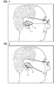
- the hearing aid device according to the invention is shown H similar to an in-the-ear hearing in the ear canal of a Carrier used.
- a boom A in which the directional microphone is housed, points according to the marked Arrow horizontally forward.
- the direction of the jib corresponds to the highest sensitivity of the directional microphone.
- the wearer In this mode, the wearer primarily takes the Sound of a source true to which the wearer's gaze directed. This corresponds to the usual hearing aid mode.
- the carrier If the carrier is now making a phone call, first Line the carrier's voice signals for transmission take. Therefore, according to FIG 2, the boom A of the hearing aid H according to the arrow marked there to the mouth the carrier turned. The earmold in the ear canal of the wearer does not change its position. The rotation of the boom A opposite the earmold is ensured by a rotary switch. The rotation then becomes not only the preferred direction the directional microphone changed, but also from switched to the phone mode in the hearing aid mode. It will the transmission device for transmitting and receiving electrical or electromagnetic signals switched on. About that In addition, the hearing aid is switched to telephone operation, in suitable filters and reinforcements specific for Phone situations are performed. By turning the Cantilever of the hearing aid device may also accept the Telephone conversation. To end the conversation turns the carrier the boom back up.
- FIG. 3 shows a block diagram of the hearing aid device in FIG the phone mode.
- a hearing aid chip HC To a hearing aid chip HC is a speaker L and a directional microphone RM connected.
- a bidirectional Data connection is the hearing aid chip HC with a Bluetooth chip BC, which is active in the telephone mode, in Connection.
- the Bluetooth chip BC sends and receives signals via an antenna A. With this configuration, it is possible that the carrier via the speaker L both the phone signals from the bluetooth chip BC as well as your own Speech signals are processed via the directional microphone RM obtained with the individual frequency response of the hearing aid chip.
- the wearer switches to the hearing aid mode by turning on the Boom on the rotary switch turns up, so is accordingly 4 shows the Bluetooth chip BC inactive, so that interrupted the bidirectional connection between the two chips is.
- the hearing aid works accordingly, as a pure hearing aid, in which exclusively the recorded via the directional microphone sound signals be prepared in the hearing aid chip accordingly.
Landscapes
- Engineering & Computer Science (AREA)
- Acoustics & Sound (AREA)
- Computer Networks & Wireless Communication (AREA)
- Otolaryngology (AREA)
- Physics & Mathematics (AREA)
- General Health & Medical Sciences (AREA)
- Health & Medical Sciences (AREA)
- Signal Processing (AREA)
- Neurosurgery (AREA)
- Circuit For Audible Band Transducer (AREA)
- Telephone Set Structure (AREA)
- Electrophonic Musical Instruments (AREA)
- Transmitters (AREA)
- Headphones And Earphones (AREA)
- Input Circuits Of Receivers And Coupling Of Receivers And Audio Equipment (AREA)
Abstract
Description
- FIG 1
- eine erfindungsgemäße Hörhilfevorrichtung beim Tragen im Hörgerätemodus;
- FIG 2
- das Hörgerät von FIG 1 im Telefonmodus;
- FIG 3
- ein Prinzipschaltbild für den Telefonmodus; und
- FIG 4
- ein Prinzipschaltbild für den Hörgerätemodus.
Claims (6)
- Hörhilfevorrichtung (H) mitgekennzeichnet durcheinem Gehäuse,einer Richtmikrofoneinrichtung (RM),einer Übertragungseinrichtung (BC) zum elektrischen oder elektromagnetischen Übertragen von Signalen zwischen der Hörhilfevorrichtung (H) und einer externen Vorrichtung undeiner Hörgeräteinrichtung (HC) zum Verstärken von Richtmikrofonsignalen, die ausschließlich direkt von der Richtmikrofoneinrichtung (RM) stammen, in einem ersten Betriebsmodus und zum Verstärken von Signalen, die von der Übertragungseinrichtung (BC) stammen, in einem zweiten Betriebsmodus,einen Drehschalter, der einen ersten und einen dazu drehbaren zweiten Abschnitt aufweist, wobei das Gehäuse mit dem ersten und die Richtmikrofoneinrichtung (RM) mit dem zweiten Abschnitt verbunden ist, so dass die Hörhilfevorrichtung (H) durch Drehen der Richtmikrofoneinrichtung relativ zum Gehäuse von dem einen in den anderen der beiden Betriebsmodi schaltbar ist.
- Hörhilfevorrichtung nach Anspruch 1, wobei in dem zweiten Betriebsmodus auch Signale von der Richtmikrofoneinrichtung (RM) verstärkbar sind.
- Hörhilfevorrichtung nach Anspruch 1 oder 2, wobei der zweite Betriebsmodus ein Telefonmodus ist und die elektromagnetisch übertragenen Signale von einem Telefon stammen.
- Hörhilfevorrichtung nach einem der vorhergehenden Ansprüche, wobei die Übertragungseinrichtung (BC) einen Bluetooth-Chip aufweist.
- Hörhilfevorrichtung nach einem der vorhergehenden Ansprüche, wobei in dem ersten Betriebsmodus die Übertragungseinrichtung (BC) inaktiv geschaltet ist.
- Hörhilfevorrichtung nach einem der vorhergehenden Ansprüche, wobei das Gehäuse durch eine Otoplastik realisiert ist.
Applications Claiming Priority (2)
| Application Number | Priority Date | Filing Date | Title |
|---|---|---|---|
| DE102004021964 | 2004-05-04 | ||
| DE102004021964A DE102004021964B3 (de) | 2004-05-04 | 2004-05-04 | Hörhilfevorrichtung |
Publications (3)
| Publication Number | Publication Date |
|---|---|
| EP1594343A2 true EP1594343A2 (de) | 2005-11-09 |
| EP1594343A3 EP1594343A3 (de) | 2007-11-07 |
| EP1594343B1 EP1594343B1 (de) | 2008-11-05 |
Family
ID=34939500
Family Applications (1)
| Application Number | Title | Priority Date | Filing Date |
|---|---|---|---|
| EP05103360A Expired - Lifetime EP1594343B1 (de) | 2004-05-04 | 2005-04-26 | Hörhilfevorrichtung und entsprechendes Betriebsverfahren |
Country Status (5)
| Country | Link |
|---|---|
| US (1) | US7450731B2 (de) |
| EP (1) | EP1594343B1 (de) |
| AT (1) | ATE413787T1 (de) |
| DE (2) | DE102004021964B3 (de) |
| DK (1) | DK1594343T3 (de) |
Cited By (2)
| Publication number | Priority date | Publication date | Assignee | Title |
|---|---|---|---|---|
| WO2008125107A1 (en) * | 2007-04-16 | 2008-10-23 | Gn Resound A/S | A hearing aid wireless communication adaptor |
| FR2923132A1 (fr) * | 2007-10-26 | 2009-05-01 | Posterexpo Sarl | Dispositif de communication audio assiste. |
Families Citing this family (7)
| Publication number | Priority date | Publication date | Assignee | Title |
|---|---|---|---|---|
| US7889681B2 (en) * | 2005-03-03 | 2011-02-15 | Cisco Technology, Inc. | Methods and devices for improving the multiple spanning tree protocol |
| DE102005017496B3 (de) * | 2005-04-15 | 2006-08-17 | Siemens Audiologische Technik Gmbh | Mikrofoneinrichtung mit Orientierungssensor und entsprechendes Verfahren zum Betreiben der Mikrofoneinrichtung |
| US20070098195A1 (en) * | 2005-10-31 | 2007-05-03 | Holmes David W | Wireless hearing aid system and method |
| DE102007005861B3 (de) * | 2007-02-06 | 2008-08-21 | Siemens Audiologische Technik Gmbh | Hörvorrichtung mit automatischer Ausrichtung des Richtmikrofons und entsprechendes Verfahren |
| US8520874B1 (en) | 2011-07-26 | 2013-08-27 | Gary Beutler | Hearing aid with an operational based switch |
| WO2013106342A1 (en) * | 2012-01-09 | 2013-07-18 | Voxx International Corporation | Personal sound amplifier |
| EP3713254B1 (de) * | 2013-11-07 | 2024-10-23 | Oticon A/s | Binaurales hörgerätesystem mit zwei drahtlosen schnittstellen |
Family Cites Families (6)
| Publication number | Priority date | Publication date | Assignee | Title |
|---|---|---|---|---|
| US3975599A (en) * | 1975-09-17 | 1976-08-17 | United States Surgical Corporation | Directional/non-directional hearing aid |
| DE4233813C1 (de) * | 1992-10-07 | 1993-11-04 | Siemens Audiologische Technik | Programmierbares hoerhilfegeraet |
| DE9320391U1 (de) * | 1993-09-15 | 1994-06-23 | Siemens Audiologische Technik Gmbh, 91058 Erlangen | Betätigungsvorrichtung für Hörgeräte |
| US6694034B2 (en) * | 2000-01-07 | 2004-02-17 | Etymotic Research, Inc. | Transmission detection and switch system for hearing improvement applications |
| US6760457B1 (en) | 2000-09-11 | 2004-07-06 | Micro Ear Technology, Inc. | Automatic telephone switch for hearing aid |
| US7013009B2 (en) * | 2001-06-21 | 2006-03-14 | Oakley, Inc. | Eyeglasses with wireless communication features |
-
2004
- 2004-05-04 DE DE102004021964A patent/DE102004021964B3/de not_active Expired - Fee Related
-
2005
- 2005-04-26 DE DE502005005849T patent/DE502005005849D1/de not_active Expired - Fee Related
- 2005-04-26 EP EP05103360A patent/EP1594343B1/de not_active Expired - Lifetime
- 2005-04-26 AT AT05103360T patent/ATE413787T1/de not_active IP Right Cessation
- 2005-04-26 DK DK05103360T patent/DK1594343T3/da active
- 2005-05-03 US US11/120,596 patent/US7450731B2/en not_active Expired - Fee Related
Cited By (2)
| Publication number | Priority date | Publication date | Assignee | Title |
|---|---|---|---|---|
| WO2008125107A1 (en) * | 2007-04-16 | 2008-10-23 | Gn Resound A/S | A hearing aid wireless communication adaptor |
| FR2923132A1 (fr) * | 2007-10-26 | 2009-05-01 | Posterexpo Sarl | Dispositif de communication audio assiste. |
Also Published As
| Publication number | Publication date |
|---|---|
| ATE413787T1 (de) | 2008-11-15 |
| DK1594343T3 (da) | 2009-03-09 |
| EP1594343A3 (de) | 2007-11-07 |
| DE502005005849D1 (de) | 2008-12-18 |
| DE102004021964B3 (de) | 2005-10-20 |
| EP1594343B1 (de) | 2008-11-05 |
| US20050249372A1 (en) | 2005-11-10 |
| US7450731B2 (en) | 2008-11-11 |
Similar Documents
| Publication | Publication Date | Title |
|---|---|---|
| EP0941014B1 (de) | Hörgerätesystem mit zwei Hörhilfegeräten | |
| EP1583395B1 (de) | IdO-Hörgerät zur binauralen Versorgung eines Patienten | |
| DE69233156T2 (de) | Verbessertes hörgerät | |
| DE102004047759B3 (de) | Verwendung eines Hörhilfegerätesystems mit wenigstens zwei Hörhilfegeräten | |
| EP1589784B1 (de) | Hörhilfegerät mit einer Bedieneinrichtung | |
| EP2811761B1 (de) | Antenneneinrichtung für Hörinstrumente | |
| EP1296537A2 (de) | Hörgerät mit automatischer Umschaltung auf Hörspulenbetrieb | |
| CH693054A5 (de) | Kommunikationsvorrichtung für Benutzer tragbarer Hörhilfen. | |
| EP1915031A2 (de) | Hörsystem mit Fernbedienung als Basisstation und entsprechendes Kommunikationsverfahren | |
| EP2180724A1 (de) | Ohrstück mit Stegen | |
| EP3322032B1 (de) | Hörhilfegerät mit elektronikrahmen und darin integrierter antenne | |
| EP2334102A2 (de) | Hörgerät mit einer platzsparenden Anordnung von Mikrofonen und Schallöffnungen | |
| EP1594343B1 (de) | Hörhilfevorrichtung und entsprechendes Betriebsverfahren | |
| EP4054208B1 (de) | Hörgerät, antenne für ein hörgerät und verfahren zur herstellung eines hörgeräts | |
| DE102008054087A1 (de) | Hörhilfegerät mit mindestens einem kapazitiven Näherungssensor | |
| DE102005006404B3 (de) | Modulares Hörgerätesystem | |
| EP2373062A2 (de) | Duales Einstellverfahren für ein Hörsystem | |
| EP3197180A1 (de) | Hörgerät | |
| EP2897377A1 (de) | HdO-Hörinstrument mit Gehäuse und Schallschlauch | |
| EP3679729A1 (de) | Mehrzweck-hochleistungshörgerät mit einem mobilen endgerät, insbesondere smartphone | |
| WO2012059428A1 (de) | Kommunikationssystem mit telefon und hörvorrichtung sowie übertragungsverfahren | |
| EP3863304B1 (de) | Hörgerät mit induktiv gekoppelter antenneneinheit | |
| DE102005005284B3 (de) | Infrarotübertragungsvorrichtung für ein Hörgerät | |
| EP2852182A1 (de) | Hörinstrument mit Batteriefachschalter | |
| WO1996003848A1 (de) | Hörhilfe |
Legal Events
| Date | Code | Title | Description |
|---|---|---|---|
| PUAI | Public reference made under article 153(3) epc to a published international application that has entered the european phase |
Free format text: ORIGINAL CODE: 0009012 |
|
| AK | Designated contracting states |
Kind code of ref document: A2 Designated state(s): AT BE BG CH CY CZ DE DK EE ES FI FR GB GR HU IE IS IT LI LT LU MC NL PL PT RO SE SI SK TR |
|
| AX | Request for extension of the european patent |
Extension state: AL BA HR LV MK YU |
|
| PUAL | Search report despatched |
Free format text: ORIGINAL CODE: 0009013 |
|
| AK | Designated contracting states |
Kind code of ref document: A3 Designated state(s): AT BE BG CH CY CZ DE DK EE ES FI FR GB GR HU IE IS IT LI LT LU MC NL PL PT RO SE SI SK TR |
|
| AX | Request for extension of the european patent |
Extension state: AL BA HR LV MK YU |
|
| 17P | Request for examination filed |
Effective date: 20071022 |
|
| GRAP | Despatch of communication of intention to grant a patent |
Free format text: ORIGINAL CODE: EPIDOSNIGR1 |
|
| AKX | Designation fees paid |
Designated state(s): AT BE BG CH CY CZ DE DK EE ES FI FR GB GR HU IE IS IT LI LT LU MC NL PL PT RO SE SI SK TR |
|
| GRAS | Grant fee paid |
Free format text: ORIGINAL CODE: EPIDOSNIGR3 |
|
| GRAA | (expected) grant |
Free format text: ORIGINAL CODE: 0009210 |
|
| AK | Designated contracting states |
Kind code of ref document: B1 Designated state(s): AT BE BG CH CY CZ DE DK EE ES FI FR GB GR HU IE IS IT LI LT LU MC NL PL PT RO SE SI SK TR |
|
| REG | Reference to a national code |
Ref country code: GB Ref legal event code: FG4D Free format text: NOT ENGLISH |
|
| REG | Reference to a national code |
Ref country code: CH Ref legal event code: EP Ref country code: CH Ref legal event code: NV Representative=s name: SIEMENS SCHWEIZ AG |
|
| REG | Reference to a national code |
Ref country code: IE Ref legal event code: FG4D Free format text: LANGUAGE OF EP DOCUMENT: GERMAN |
|
| REF | Corresponds to: |
Ref document number: 502005005849 Country of ref document: DE Date of ref document: 20081218 Kind code of ref document: P |
|
| REG | Reference to a national code |
Ref country code: DK Ref legal event code: T3 |
|
| REG | Reference to a national code |
Ref country code: CH Ref legal event code: PCAR Free format text: SIEMENS SCHWEIZ AG;INTELLECTUAL PROPERTY FREILAGERSTRASSE 40;8047 ZUERICH (CH) |
|
| NLV1 | Nl: lapsed or annulled due to failure to fulfill the requirements of art. 29p and 29m of the patents act | ||
| LTIE | Lt: invalidation of european patent or patent extension |
Effective date: 20081105 |
|
| PG25 | Lapsed in a contracting state [announced via postgrant information from national office to epo] |
Ref country code: ES Free format text: LAPSE BECAUSE OF FAILURE TO SUBMIT A TRANSLATION OF THE DESCRIPTION OR TO PAY THE FEE WITHIN THE PRESCRIBED TIME-LIMIT Effective date: 20090216 Ref country code: LT Free format text: LAPSE BECAUSE OF FAILURE TO SUBMIT A TRANSLATION OF THE DESCRIPTION OR TO PAY THE FEE WITHIN THE PRESCRIBED TIME-LIMIT Effective date: 20081105 |
|
| PG25 | Lapsed in a contracting state [announced via postgrant information from national office to epo] |
Ref country code: PL Free format text: LAPSE BECAUSE OF FAILURE TO SUBMIT A TRANSLATION OF THE DESCRIPTION OR TO PAY THE FEE WITHIN THE PRESCRIBED TIME-LIMIT Effective date: 20081105 Ref country code: IS Free format text: LAPSE BECAUSE OF FAILURE TO SUBMIT A TRANSLATION OF THE DESCRIPTION OR TO PAY THE FEE WITHIN THE PRESCRIBED TIME-LIMIT Effective date: 20090305 Ref country code: FI Free format text: LAPSE BECAUSE OF FAILURE TO SUBMIT A TRANSLATION OF THE DESCRIPTION OR TO PAY THE FEE WITHIN THE PRESCRIBED TIME-LIMIT Effective date: 20081105 Ref country code: NL Free format text: LAPSE BECAUSE OF FAILURE TO SUBMIT A TRANSLATION OF THE DESCRIPTION OR TO PAY THE FEE WITHIN THE PRESCRIBED TIME-LIMIT Effective date: 20081105 Ref country code: SI Free format text: LAPSE BECAUSE OF FAILURE TO SUBMIT A TRANSLATION OF THE DESCRIPTION OR TO PAY THE FEE WITHIN THE PRESCRIBED TIME-LIMIT Effective date: 20081105 |
|
| REG | Reference to a national code |
Ref country code: IE Ref legal event code: FD4D |
|
| PG25 | Lapsed in a contracting state [announced via postgrant information from national office to epo] |
Ref country code: RO Free format text: LAPSE BECAUSE OF FAILURE TO SUBMIT A TRANSLATION OF THE DESCRIPTION OR TO PAY THE FEE WITHIN THE PRESCRIBED TIME-LIMIT Effective date: 20081105 Ref country code: BG Free format text: LAPSE BECAUSE OF FAILURE TO SUBMIT A TRANSLATION OF THE DESCRIPTION OR TO PAY THE FEE WITHIN THE PRESCRIBED TIME-LIMIT Effective date: 20090205 Ref country code: EE Free format text: LAPSE BECAUSE OF FAILURE TO SUBMIT A TRANSLATION OF THE DESCRIPTION OR TO PAY THE FEE WITHIN THE PRESCRIBED TIME-LIMIT Effective date: 20081105 Ref country code: IE Free format text: LAPSE BECAUSE OF FAILURE TO SUBMIT A TRANSLATION OF THE DESCRIPTION OR TO PAY THE FEE WITHIN THE PRESCRIBED TIME-LIMIT Effective date: 20081105 |
|
| PG25 | Lapsed in a contracting state [announced via postgrant information from national office to epo] |
Ref country code: SE Free format text: LAPSE BECAUSE OF FAILURE TO SUBMIT A TRANSLATION OF THE DESCRIPTION OR TO PAY THE FEE WITHIN THE PRESCRIBED TIME-LIMIT Effective date: 20090205 Ref country code: CZ Free format text: LAPSE BECAUSE OF FAILURE TO SUBMIT A TRANSLATION OF THE DESCRIPTION OR TO PAY THE FEE WITHIN THE PRESCRIBED TIME-LIMIT Effective date: 20081105 Ref country code: PT Free format text: LAPSE BECAUSE OF FAILURE TO SUBMIT A TRANSLATION OF THE DESCRIPTION OR TO PAY THE FEE WITHIN THE PRESCRIBED TIME-LIMIT Effective date: 20090406 |
|
| PLBE | No opposition filed within time limit |
Free format text: ORIGINAL CODE: 0009261 |
|
| STAA | Information on the status of an ep patent application or granted ep patent |
Free format text: STATUS: NO OPPOSITION FILED WITHIN TIME LIMIT |
|
| PG25 | Lapsed in a contracting state [announced via postgrant information from national office to epo] |
Ref country code: SK Free format text: LAPSE BECAUSE OF FAILURE TO SUBMIT A TRANSLATION OF THE DESCRIPTION OR TO PAY THE FEE WITHIN THE PRESCRIBED TIME-LIMIT Effective date: 20081105 |
|
| 26N | No opposition filed |
Effective date: 20090806 |
|
| BERE | Be: lapsed |
Owner name: SIEMENS AUDIOLOGISCHE TECHNIK G.M.B.H. Effective date: 20090430 |
|
| REG | Reference to a national code |
Ref country code: CH Ref legal event code: PL |
|
| REG | Reference to a national code |
Ref country code: DK Ref legal event code: EBP |
|
| GBPC | Gb: european patent ceased through non-payment of renewal fee |
Effective date: 20090426 |
|
| REG | Reference to a national code |
Ref country code: FR Ref legal event code: ST Effective date: 20091231 |
|
| PG25 | Lapsed in a contracting state [announced via postgrant information from national office to epo] |
Ref country code: LI Free format text: LAPSE BECAUSE OF NON-PAYMENT OF DUE FEES Effective date: 20090430 Ref country code: CH Free format text: LAPSE BECAUSE OF NON-PAYMENT OF DUE FEES Effective date: 20090430 Ref country code: DE Free format text: LAPSE BECAUSE OF NON-PAYMENT OF DUE FEES Effective date: 20091103 |
|
| PG25 | Lapsed in a contracting state [announced via postgrant information from national office to epo] |
Ref country code: FR Free format text: LAPSE BECAUSE OF NON-PAYMENT OF DUE FEES Effective date: 20091222 Ref country code: GB Free format text: LAPSE BECAUSE OF NON-PAYMENT OF DUE FEES Effective date: 20090426 Ref country code: MC Free format text: LAPSE BECAUSE OF NON-PAYMENT OF DUE FEES Effective date: 20090430 Ref country code: DK Free format text: LAPSE BECAUSE OF NON-PAYMENT OF DUE FEES Effective date: 20090430 |
|
| PG25 | Lapsed in a contracting state [announced via postgrant information from national office to epo] |
Ref country code: BE Free format text: LAPSE BECAUSE OF NON-PAYMENT OF DUE FEES Effective date: 20090430 |
|
| PG25 | Lapsed in a contracting state [announced via postgrant information from national office to epo] |
Ref country code: AT Free format text: LAPSE BECAUSE OF NON-PAYMENT OF DUE FEES Effective date: 20090426 |
|
| PG25 | Lapsed in a contracting state [announced via postgrant information from national office to epo] |
Ref country code: GR Free format text: LAPSE BECAUSE OF FAILURE TO SUBMIT A TRANSLATION OF THE DESCRIPTION OR TO PAY THE FEE WITHIN THE PRESCRIBED TIME-LIMIT Effective date: 20090206 |
|
| PG25 | Lapsed in a contracting state [announced via postgrant information from national office to epo] |
Ref country code: IT Free format text: LAPSE BECAUSE OF NON-PAYMENT OF DUE FEES Effective date: 20090426 |
|
| PG25 | Lapsed in a contracting state [announced via postgrant information from national office to epo] |
Ref country code: LU Free format text: LAPSE BECAUSE OF NON-PAYMENT OF DUE FEES Effective date: 20090426 |
|
| PG25 | Lapsed in a contracting state [announced via postgrant information from national office to epo] |
Ref country code: HU Free format text: LAPSE BECAUSE OF FAILURE TO SUBMIT A TRANSLATION OF THE DESCRIPTION OR TO PAY THE FEE WITHIN THE PRESCRIBED TIME-LIMIT Effective date: 20090506 |
|
| PG25 | Lapsed in a contracting state [announced via postgrant information from national office to epo] |
Ref country code: TR Free format text: LAPSE BECAUSE OF FAILURE TO SUBMIT A TRANSLATION OF THE DESCRIPTION OR TO PAY THE FEE WITHIN THE PRESCRIBED TIME-LIMIT Effective date: 20081105 |
|
| PG25 | Lapsed in a contracting state [announced via postgrant information from national office to epo] |
Ref country code: CY Free format text: LAPSE BECAUSE OF FAILURE TO SUBMIT A TRANSLATION OF THE DESCRIPTION OR TO PAY THE FEE WITHIN THE PRESCRIBED TIME-LIMIT Effective date: 20081105 |