EP1589784B1 - Hörhilfegerät mit einer Bedieneinrichtung - Google Patents
Hörhilfegerät mit einer Bedieneinrichtung Download PDFInfo
- Publication number
- EP1589784B1 EP1589784B1 EP05103005A EP05103005A EP1589784B1 EP 1589784 B1 EP1589784 B1 EP 1589784B1 EP 05103005 A EP05103005 A EP 05103005A EP 05103005 A EP05103005 A EP 05103005A EP 1589784 B1 EP1589784 B1 EP 1589784B1
- Authority
- EP
- European Patent Office
- Prior art keywords
- hearing aid
- proximity sensor
- hand
- hearing
- aid according
- Prior art date
- Legal status (The legal status is an assumption and is not a legal conclusion. Google has not performed a legal analysis and makes no representation as to the accuracy of the status listed.)
- Expired - Lifetime
Links
Images

Classifications
-
- H—ELECTRICITY
- H04—ELECTRIC COMMUNICATION TECHNIQUE
- H04R—LOUDSPEAKERS, MICROPHONES, GRAMOPHONE PICK-UPS OR LIKE ACOUSTIC ELECTROMECHANICAL TRANSDUCERS; ELECTRIC HEARING AIDS; PUBLIC ADDRESS SYSTEMS
- H04R25/00—Electric hearing aids
-
- H—ELECTRICITY
- H03—ELECTRONIC CIRCUITRY
- H03G—CONTROL OF AMPLIFICATION
- H03G3/00—Gain control in amplifiers or frequency changers
- H03G3/02—Manually-operated control
- H03G3/04—Manually-operated control in untuned amplifiers
-
- H—ELECTRICITY
- H03—ELECTRONIC CIRCUITRY
- H03K—PULSE TECHNIQUE
- H03K17/00—Electronic switching or gating, i.e. not by contact-making and –breaking
- H03K17/94—Electronic switching or gating, i.e. not by contact-making and –breaking characterised by the way in which the control signals are generated
- H03K17/945—Proximity switches
- H03K17/95—Proximity switches using a magnetic detector
- H03K17/9502—Measures for increasing reliability
-
- H—ELECTRICITY
- H04—ELECTRIC COMMUNICATION TECHNIQUE
- H04R—LOUDSPEAKERS, MICROPHONES, GRAMOPHONE PICK-UPS OR LIKE ACOUSTIC ELECTROMECHANICAL TRANSDUCERS; ELECTRIC HEARING AIDS; PUBLIC ADDRESS SYSTEMS
- H04R2225/00—Details of deaf aids covered by H04R25/00, not provided for in any of its subgroups
- H04R2225/025—In the ear hearing aids [ITE] hearing aids
-
- H—ELECTRICITY
- H04—ELECTRIC COMMUNICATION TECHNIQUE
- H04R—LOUDSPEAKERS, MICROPHONES, GRAMOPHONE PICK-UPS OR LIKE ACOUSTIC ELECTROMECHANICAL TRANSDUCERS; ELECTRIC HEARING AIDS; PUBLIC ADDRESS SYSTEMS
- H04R2225/00—Details of deaf aids covered by H04R25/00, not provided for in any of its subgroups
- H04R2225/61—Aspects relating to mechanical or electronic switches or control elements, e.g. functioning
-
- H—ELECTRICITY
- H04—ELECTRIC COMMUNICATION TECHNIQUE
- H04R—LOUDSPEAKERS, MICROPHONES, GRAMOPHONE PICK-UPS OR LIKE ACOUSTIC ELECTROMECHANICAL TRANSDUCERS; ELECTRIC HEARING AIDS; PUBLIC ADDRESS SYSTEMS
- H04R25/00—Electric hearing aids
- H04R25/60—Mounting or interconnection of hearing aid parts, e.g. inside tips, housings or to ossicles
- H04R25/603—Mounting or interconnection of hearing aid parts, e.g. inside tips, housings or to ossicles of mechanical or electronic switches or control elements
Definitions
- the invention relates to a hearing aid with at least one operating device.
- a hearing aid is known in which a pressure or position sensor in film design is available as an operating element.
- the sensor is mounted on the outside of the case and is already responsive to light touch.
- the sensor switch has the disadvantage that it requires a relatively large amount of space on the outside of the housing and must be touched directly to trigger a switching function.
- a hearing aid which has switches for performing operating functions. Furthermore, magnetic switches are provided in the known hearing aid, with magnetic fields in their electrical conductivity influenceable elements, such as reed contacts or magnetic field semiconductors have. Thus, by switching a magnet manually a switching function can be triggered.
- the magnetically actuated switches can also serve, in the introduction of an existing outside of the device magnetic field, such as that of a telephone receiver, in the device an additional device, such as to improve the
- a disadvantage of the known hearing aid is that, similar to the use of a remote control, also here additional means (magnets) must be present in order to trigger a switching function.
- the object of the invention is therefore to improve the direct operation of a hearing aid by hand.
- the invention offers the advantage that no operating element on the hearing aid device must be touched directly to trigger an operating function. Furthermore, it is also not necessary to carry a remote control or other technical aids (magnets).
- a switching function is already triggered by the fact that the hearing aid wearer brings a hand and in particular one or more fingers of the hand in the vicinity of the hearing aid.
- the existing at the hearing aid proximity sensor detects this and then performs the connected to the proximity sensor switching function. In this case, both the entry of the hand into the detection range of the proximity sensor trigger the switching function as well as the emergence of the hand from the detection area.
- a certain time sequence of the entry or exit of the hand in the detection area or from the detection area must be maintained, so that a switching function is triggered.
- a switching function is only triggered when the hand exits the detection area within a period of 2 to 3 seconds after entering the detection area.
- a further embodiment of the invention provides that a specific time sequence of a repeated entry and / or exit must be made so that the relevant operating function is triggered.
- a switching function is only triggered when the hand of the hearing aid wearer enters and exits the detection area of the proximity sensor three times within 5 seconds. Unintentional switching is thereby largely excluded.
- the above times are preferably adjustable by programming the hearing aid.
- this also makes it possible to adapt to the wishes of the hearing aid wearer with regard to the set times and switching patterns.
- the operating function performed by the proximity sensor preferably relates to the setting of the active hearing program or the volume control.
- the program number e.g., Program 3
- a further switching function then leads to the setting of the hearing program with the lowest number of programs (hearing program 1).
- Another variant of the invention provides that different operating functions are triggered by different temporal sequences of the entry and exit of the hand in or out of the detection range of the proximity sensor in one and the same hearing aid. For example, with two inputs and Within a certain period of time the program number is decreased by one and the program number is increased by one when entering and exiting three times compared to the originally set hearing program.
- volume control advantageously not only the entry or exit of the hand into or out of the detection area is registered, but also the distance and in particular a change in the distance of the hand from the proximity sensor during the switching operation. Then, by a particular switching pattern, i. a certain time sequence of entry or exit of the hand, not immediately executed a switching function, but the hearing aid first transferred to a state in which changes in the distance of the hand of the hearing aid wearer are detected to the proximity sensor. For example, an increase in the distance can cause an increase in the set volume. Conversely, the volume is reduced when the hand is brought closer to the hearing aid. Similarly, the program switching, starting from a specific hearing program, to a higher or lower hearing program can be performed by a corresponding evaluation of the change in the distance.
- the hearing aid wearer can advantageously receive a perceptible signal for confirming correct operation of the hearing aid in conjunction with the proximity sensor. For example beep tones are generated after a program switch and fed to the hearing of the hearing aid wearer, the number of which can detect the program number of the now active hearing program.
- a change in the distance of the triggering hand is registered, can advantageously already of the Hearing aid detected first step by an acoustic signal (eg one-time short beep) are displayed, even if it is still no change in the signal processing in the hearing aid related parameter is connected.
- the detection range of the proximity sensor used is relatively narrow.
- a switching function is only triggered when the hand is at a distance of a few centimeters to the proximity sensor. Only in exceptional cases, with a distance of the hand of more than 10 cm still a switching function is performed.
- the detection range of the proximity sensor can be adjusted during the programming of the hearing aid device and thus adapted to the needs of the hearing aid wearer.
- An embodiment of the invention provides that different switching functions are performed depending on the distance in which the hand is guided in front of the proximity sensor. For example, in the case of a hand which is guided very close to the ear in front of the proximity sensor, a first switching function is triggered and a second switching function, which is different from the first switching function, is triggered when the hand is guided relatively far away from the ear (for example more than 10 cm) in front of the proximity sensor.
- a further embodiment of the invention provides for the use of a plurality of proximity sensors in a hearing aid, which differ with respect to their detection range relative to the hearing aid.
- a first proximity sensor can respond to a hand brought very close to the hearing aid (eg, at a distance of less than 3 cm) and initiate a switching function
- a second proximity sensor responds to a hand brought in at a greater distance (eg, greater than 8 cm) and a second switching function triggers.
- the detection ranges of the proximity sensors with respect to The hearing aid may differ not only in the distance, but also in the orientation.
- a first detection area in the viewing direction and a second detection area may be oriented in the opposite direction.
- proximity sensors can also be used to avoid faulty circuits.
- a switching function is triggered only when the hand is first detected by the first proximity sensor, then detected by the two proximity sensors, subsequently detected only by the first proximity sensor, and finally by neither of the two proximity sensors more is detected, whereby the entire process must occur within a short time (eg 2 sec). It can thus generally be determined in a simple manner, from which direction the hand must be brought to the hearing aid and in which direction it must be removed again in order to trigger a specific switching function. Unintentional triggering of a switching function is thus largely excluded.
- the distance of the hand to the proximity sensor is preferably adjusted so that only at a very small distance a switching function is triggered.
- a switching function is triggered only when one grabs with a finger directly into the concha of the respective ear and thus effectively covers the auditory canal entrance. Unintentional switching is thereby largely excluded.
- the proximity sensor used in connection with the invention is not limited to a specific operating principle. All current proximity sensors which allow a corresponding miniaturization, can be used in connection with the invention, such as infrared proximity sensors, Ultrasonic proximity sensors, inductive proximity sensors or capacitive proximity sensors.
- the invention is not limited to a particular switching function. Rather, in principle, all executable in hearing aids switching functions can also be performed in conjunction with the proximity sensor according to the invention. Furthermore, it is possible to determine by programming the hearing aid device which switching function is carried out in conjunction with the proximity sensor. It is also possible for a binaural supply to trigger a different switching function for the hearing aid worn on or in the left ear than for the hearing aid worn on or in the right ear. Preferably, the respectively executed switching function then acts by coupling the two hearing aid devices to both hearing aid devices.
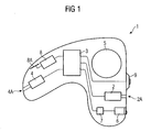
- FIG. 1 shows a hearing aid 1 portable in the ear with its essential components. These are a microphone 2 with a sound inlet opening 2A for receiving an acoustic signal and conversion into an electrical signal. The electrical signal is supplied to a signal processing unit 3 for further processing and frequency-dependent amplification. Finally, the processed and amplified signal converted back by an earphone 4 of an electrical signal into an acoustic signal and delivered via the sound channel 4A in the ear canal of a hearing aid device wearer. To power the electrical components of the hearing aid 1, a battery 5 is used.
- the hearing aid device 1 is adaptable in terms of its transmission characteristics to different listening situations (eg “quiet environment”, “conversation”, “conversation in a noisy environment”, “driving in the car”, etc.).
- the selection is made by setting certain parameter sets (hearing programs), which adapt the signal processing to the respective listening situation. Between the individual hearing programs is switched by operation of the hearing aid 1.
- the operation for program switching by means of a proximity sensor 6. This registers the entry and exit of an object in its coverage.
- the proximity sensor 6 is assigned an evaluation unit 7.
- certain switching patterns can be determined by programming the hearing aid 1, which must be complied with to perform a specific switching function.
- the hearing aid device 1 can be adjusted, for example, so that the triggering object, preferably the hand of the hearing aid wearer, has to be brought into the detection range of the proximity sensor 6 three times over a period of about 3 seconds and then removed again. If such a switching pattern has been detected, a program switch can be made for a short time in the hearing aid device 1. For this purpose, the hand must be brought again into the detection range of the proximity sensor 6, wherein now the distance of the hand to the proximity sensor 6 is determined. A reduction of the distance then causes a switch to a hearing program with a lower number of programs, for example from hearing program 4 to hearing program 3. However, if the distance is increased, this leads to switching in a hearing program with a higher number of programs, eg from hearing program 4 to hearing program 5.
- the hearing aid device 1 comprises, as a further component, a transmitting and receiving unit 8 with an antenna 8A for wireless data exchange with a further hearing aid device for the binaural supply of a hearing aid wearer.
- a program switchover caused in the manner described is thereby also transmitted to the second hearing aid device, which thereby performs the same program switchover.
- the second hearing aid device of the same type by means of a proximity sensor 6 corresponding proximity sensor analogously a change in the volume setting done, which is then transmitted via the antenna 8A and the transmitting and receiving unit to the hearing aid 1 and there causes an analog volume change.
- a push-button switch 9 is provided by the direct contact also a switching function can be triggered.
- This switching function may be to turn on or off a noise removal algorithm.
- a switching function can be performed in the hearing aid 1 according to the embodiment without direct contact of a control element.
- the invention is therefore particularly in ear hearing aids and in particular ear canal devices advantageous because there is hardly any space for attachment of conventional controls and continue to be common control elements also difficult to access. Nevertheless, the invention is not limited to hearing aids that are portable in the ear, but in principle applicable to all known types of hearing aid devices.
- FIG. 2 shows an auricle 10 for a side view of the head.
- a hearing aid device 11 which can be worn in the ear, which for the most part projects into the auditory canal (not shown).
- the hearing aid device 11 according to the embodiment comprises two spaced-apart proximity sensors 12A and 12B. If now the hand 13 of the hearing aid wearer is brought close to the hearing aid device 11 in a specific, predefined rhythm and then removed again, as indicated by the double arrow 14, this triggers an operating function.
- a switching function is always triggered in the hearing aid device 11 only when the hand is first detected by the proximity sensor 12A, subsequently detected by both proximity sensors 12A and 12B, then again detected only by the proximity sensor 12A and subsequently is no longer detected by any of the two proximity sensors.
- a switching function is thus triggered in the embodiment only when the hand is guided from the front (from the direction of the front of the head) in front of the ear and removed again to the front.
- the relevant switching function is only triggered when the triggering movement pattern within a short time, eg within 2 sec, is executed.
- a switching function is triggered only when the hand 13 is first led past the ear from the front to the back (until it lies outside the detection ranges of both proximity sensors 12A, 12B) and then again from behind to the front Ear is led past.
- the detection ranges of the two proximity sensors can also be oriented differently, so that the detection range of the proximity sensor 12A is laterally directed forward, while the detection range of the proximity sensor 12B is directed laterally to the rear. Then a hand guided from the front to the ear can trigger a different switching function than a hand guided from behind to the ear.
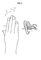
- FIG. 3 shows the external auditory canal with the hearing aid 11 located therein in longitudinal section.
- FIG. 3 illustrates that in addition to a movement of the hand 13 in the direction of the double arrow 14 and a movement in the direction of the double arrow 15, ie towards the ear or away, is possible.
- the hearing aid device 11 with the proximity sensors 12A and 12B (concealed) can first be transferred into a mode in which the distance between the hand 13 and the proximity sensors and, in particular, a change in this distance are evaluated becomes. This can be, as in the comments to FIG. 1 described, also more complex switching functions (eg volume control) perform.
- the invention further offers the possibility that different switching functions are performed depending on the distance in which the hand 13 is guided in front of the proximity sensors 12A and 12B. For example, in the case of a hand 13 which is guided very close to the ear in front of the proximity sensors, a program switchover is carried out and an algorithm for feedback suppression is switched on and at a hand 13 guided in a relatively large distance from the ear (eg more than 10 cm) in front of the proximity sensors 12A and 12B . switched off.
- a program switchover is carried out and an algorithm for feedback suppression is switched on and at a hand 13 guided in a relatively large distance from the ear (eg more than 10 cm) in front of the proximity sensors 12A and 12B . switched off.
Landscapes
- Acoustics & Sound (AREA)
- General Health & Medical Sciences (AREA)
- Neurosurgery (AREA)
- Otolaryngology (AREA)
- Physics & Mathematics (AREA)
- Engineering & Computer Science (AREA)
- Signal Processing (AREA)
- Health & Medical Sciences (AREA)
- Telephone Function (AREA)
- Fittings On The Vehicle Exterior For Carrying Loads, And Devices For Holding Or Mounting Articles (AREA)
- Transceivers (AREA)
- Transmitters (AREA)
- Headphones And Earphones (AREA)
- Arrangement Of Elements, Cooling, Sealing, Or The Like Of Lighting Devices (AREA)
Description
- Die Erfindung betrifft ein Hörhilfegerät mit wenigstens einer Bedieneinrichtung.
- Durch den Fortschritt in der Halbleiterbauelemente-Technik ist es möglich, Hörhilfegeräte immer weiter zu miniaturisieren. Dabei stellt sich jedoch das Problem, dass durch die kleiner werdenden Gehäuse immer weniger Platz für Bedienelemente zur Verfügung steht. Es werden daher zur Bedienung von Hörhilfegeräten häufig Fernbedienungen verwendet. Diese haben jedoch den Nachteil, dass sie stets zusätzlich zu den Hörhilfegeräten mitgeführt werden müssen.
- Aus der
US 2002/0068537 A1 ist ein Mobiltelefon mit einem Sensor (Proximity-Sensor) bekannt. Dieser Sensor misst den Abstand zwischen dem Telefon und dem Kopf des Benutzers. Mit dem Sensorausgangssignal kann die Verstärkung des Lautsprechers oder des Mikrophons in Abhängigkeit von diesem Abstand gesteuert werden. - Aus der
US 5,341,433 ist ein Hörgerät bekannt, bei dem als Bedienelement ein Druck- oder Positionssensor in Film-Auslegung vorhanden ist. Der Sensor ist auf der Außenseite des Gehäuses angebracht und reagiert bereits auf leichte Berührung. Der Sensor-Schalter hat den Nachteil, dass er verhältnismäßig viel Platz auf der Außenseite des Gehäuses beansprucht und zum Auslösen einer Schaltfunktion direkt berührt werden muss. - Aus der
DE 31 09 049 A1 ist ein Hörgerät bekannt, welches zum Durchführen von Bedienfunktionen Schalter aufweist. Weiterhin sind bei dem bekannten Hörgerät magnetische Schalter vorgesehen, die mit Magnetfeldern in ihrer elektrischen Leitfähigkeit beeinflussbare Elemente, z.B. Reed-Kontakte oder Magnetfeld-Halbleiter, aufweisen. So kann durch Verschieben eines Magnetes manuell eine Schaltfunktion ausgelöst werden. Die magnetisch betätigbaren Schalter können aber auch dazu dienen, beim Heranführen eines außerhalb des Geräts vorhandenen Magnetfeldes, etwa desjenigen eines Telefonhörers, im Gerät eine Zusatzeinrichtung, etwa eine solche zur Verbesserung der - Aufnahme eines Telefongespräches (Induktionsspule), selbsttätig einzuschalten.
- Nachteilig bei dem bekannten Hörgerät ist, dass, ähnlich wie bei der Verwendung einer Fernbedienung, auch hier zusätzliche Mittel (Magnete) vorhanden sein müssen, um eine Schaltfunktion auszulösen.
- Aufgabe der Erfindung ist es daher, die direkte Bedienung eines Hörhilfegerätes von Hand zu verbessern.
- Diese Aufgabe wird durch ein Hörhilfegerät mit den Merkmalen gemäß Anspruch 1 gelöst.
- Die Erfindung bietet den Vorteil, dass zum Auslösen einer Bedienfunktion kein Bedienelement am Hörhilfegerät direkt berührt werden muss. Weiterhin ist es auch nicht erforderlich, eine Fernbedienung oder weitere technische Hilfsmittel (Magnete) mitzuführen. Eine Schaltfunktion wird bereits dadurch ausgelöst, dass der Hörhilfegeräteträger eine Hand und insbesondere einen oder mehrere Finger der Hand in die Nähe des Hörhilfegerätes bringt. Der bei dem Hörhilfegerät vorhandene Näherungssensor erkennt dies und führt daraufhin die mit dem Näherungssensor verbundene Schaltfunktion aus. Dabei kann sowohl das Eintreten der Hand in den Erfassungsbereich des Näherungssensors die Schaltfunktion auslösen als auch das Austreten der Hand aus dem Erfassungsbereich.
- Um Fehlschaltungen zu vermeiden, ist bei einer Ausführungsform der Erfindung vorgesehen, dass eine bestimmte zeitliche Abfolge des Ein- bzw. Austretens der Hand in den Erfassungsbereich bzw. aus dem Erfassungsbereich eingehalten werden muss, damit eine Schaltfunktion ausgelöst wird. Z.B. wird eine Schaltfunktion nur dann ausgelöst, wenn die Hand nach dem Eintreten in den Erfassungsbereich innerhalb eines Zeitraums von 2 bis 3 sec wieder aus dem Erfassungsbereich austritt. Eine weitere Ausführungsform der Erfindung sieht vor, dass eine bestimmte zeitliche Abfolge eines mehrmaligen Ein-und/oder Austretens erfolgen muss, damit die betreffende Bedienfunktion ausgelöst wird. Beispielsweise wird eine Schaltfunktion nur dann ausgelöst, wenn die Hand des Hörhilfegeräteträgers innerhalb von 5 sec dreimal in den Erfassungsbereich des Näherungssensors ein- und wieder austritt. Ein unbeabsichtigtes Schalten wird dadurch weitgehend ausgeschlossen.
- Die oben genannten Zeiten sind vorzugsweise durch Programmieren des Hörhilfegerätes einstellbar. Insbesondere ist dadurch auch eine Anpassung an die Wünsche des Hörhilfegeräteträgers bezüglich der eingestellten Zeiten und Schaltmuster möglich.
- Die durch den Näherungssensor ausgeführte Bedienfunktion betrifft vorzugsweise die Einstellung des aktiven Hörprogramms oder die Lautstärkeregelung. Beispielsweise kann so bei jeder ordnungsgemäß ausgeführten Schaltfunktion die Programmzahl (z.B. Hörprogramm 3) um eins erhöht werden, bis das Hörprogramm mit der höchsten Programmzahl eingestellt ist. Eine weitere Schaltfunktion führt dann zur Einstellung des Hörprogramms mit der niedrigsten Programmzahl (Hörprogramm 1).
- Eine andere Variante der Erfindung sieht vor, dass durch unterschiedliche zeitliche Abfolgen des Ein- und Austretens der Hand in bzw. aus dem Erfassungsbereich des Näherungssensors bei ein und demselben Hörhilfegerät verschiedene Bedienfunktionen ausgelöst werden. Z.B. kann bei zweimaligem Ein- und Austreten der Hand innerhalb eines bestimmten Zeitraums die Programmzahl um eins erniedrigt und bei dreimaligem Ein- und Austreten die Programmzahl gegenüber dem ursprünglich eingestellten Hörprogramm um eins erhöht werden.
- Insbesondere bei der Lautstärkeregelung wird vorteilhaft nicht nur das Ein- oder Austreten der Hand in bzw. aus dem Erfassungsbereich registriert, sondern auch der Abstand und insbesondere eine Veränderung des Abstandes der Hand von dem Näherungssensor während des Umschaltvorganges. Dann wird durch ein bestimmtes Schaltmuster, d.h. eine bestimmte zeitliche Abfolge des Ein- bzw. Austretens der Hand, nicht sogleich eine Schaltfunktion ausgeführt, sondern das Hörhilfegerät zunächst in einen Zustand überführt, in dem Veränderungen des Abstandes der Hand des Hörhilfegeräteträgers zu dem Näherungssensor erkannt werden. So kann beispielsweise eine Erhöhung des Abstandes eine Erhöhung der eingestellten Lautstärke bewirken. Umgekehrt wird die Lautstärke reduziert, wenn die Hand näher an das Hörhilfegerät herangeführt wird. Analog kann auch die Programmumschaltung, ausgehend von einem bestimmten Hörprogramm, zu einem höheren bzw. niedrigeren Hörprogramm durch eine entsprechende Auswertung der Veränderung des Abstandes durchgeführt werden.
- Bei einer gemäß der Erfindung ausgeführten Schaltfunktion kann der Hörhilfegeräteträger vorteilhaft ein wahrnehmbares Signal erhalten zur Bestätigung einer korrekt durchgeführten Bedienung des Hörhilfegerätes in Verbindung mit dem Näherungssensor. Beispielsweise werden nach einer Programmumschaltung Beep-Töne erzeugt und dem Gehör des Hörhilfegeräteträgers zugeführt, deren Anzahl die Programmzahl des nun aktiven Hörprogramms erkennen lassen. Insbesondere bei der oben beschriebenen Bedienung in mehreren Schritten, bei der das zu bedienende Hörhilfegerät im ersten Schritt zunächst in einen Zustand versetzt wird, von dem ausgehend in einem zweiten Schritt eine Veränderung des Abstandes der auslösenden Hand registriert wird, kann vorteilhaft auch bereits der von dem Hörhilfegerät erkannte erste Schritt durch ein akustisches Signal (z.B. einmaliger kurzer Beep) angezeigt werden, auch wenn damit noch keine Veränderung eines die Signalverarbeitung im Hörhilfegerät betreffenden Parameters verbunden ist.
- Um unbeabsichtigte Schaltfunktionen zu verhindern, ist der Erfassungsbereich des verwendeten Näherungssensors verhältnismäßig eng begrenzt. Vorzugsweise wird eine Schaltfunktion nur dann ausgelöst, wenn sich die Hand in einem Abstand von wenigen Zentimetern zum Näherungssensor befindet. Nur in Ausnahmefällen wird bei einem Abstand der Hand von mehr als 10 cm noch eine Schaltfunktion ausgeführt. Bei einer bevorzugten Ausführungsform der Erfindung kann der Erfassungsbereich des Näherungssensors bei der Programmierung des Hörhilfegerätes eingestellt und damit an die Bedürfnisse des Hörhilfegeräteträgers angepasst werden.
- Eine Ausführungsform der Erfindung sieht vor, dass in Abhängigkeit des Abstandes, in dem die Hand vor den Näherungssensor geführt wird, unterschiedliche Schaltfunktionen ausgeführt werden. Beispielsweise wird bei einer sehr dicht am Ohr vor den Näherungssensor geführten Hand eine erste Schaltfunktion ausgelöst und bei einer in relativ großem Abstand zu dem Ohr (z.B. mehr als 10 cm) vor den Näherungssensor geführter Hand eine zweite, von der ersten Schaltfunktion verschiedene Schaltfunktion ausgelöst.
- Eine weitere Ausführungsform der Erfindung sieht die Verwendung mehrerer Näherungssensoren bei einem Hörhilfegerät vor, die sich hinsichtlich ihres Erfassungsbereiches relativ zum Hörhilfegerät unterscheiden. So kann ein erster Näherungssensor auf eine sehr nah an das Hörhilfegerät (z.B. in einen Abstand von weniger als 3 cm) herangeführte Hand reagieren und eine Schaltfunktion auslösen, während ein zweiter Näherungssensor auf eine in größerem Abstand (z.B. größer 8 cm) herangeführte Hand reagiert und eine zweite Schaltfunktion auslöst. Die Erfassungsbereiche der Näherungssensoren bezüglich des Hörhilfegerätes können sich nicht nur hinsichtlich des Abstandes, sondern auch bezüglich der Ausrichtung unterscheiden. So kann ein erster Erfassungsbereich in Blickrichtung und ein zweiter Erfassungsbereich in entgegengesetzte Richtung ausgerichtet sein.
- Es können auch mehrere Näherungssensoren verwendet werden, um Fehlschaltungen zu vermeiden. So wird beispielsweise bei einem Hörhilfegerät mit zwei Näherungssensoren nur dann eine Schaltfunktion ausgelöst, wenn die Hand zunächst von dem ersten Näherungssensor erfasst wird, anschließend von den beiden Näherungssensoren erfasst wird, anschließend nur wieder von dem ersten Näherungssensor erfasst wird und schließlich von keinem der beiden Näherungssensoren mehr erfasst wird, wobei sich der gesamte Vorgang innerhalb kurzer Zeit (z.B. 2 sec) ereignen muss. Es kann damit allgemein auf einfache Weise festgelegt werden, aus welcher Richtung die Hand an das Hörhilfegerät herangeführt werden muss und in welche Richtung sie wieder entfernt werden muss, um eine bestimmte Schaltfunktion auszulösen. Ein unbeabsichtigtes Auslösen einer Schaltfunktion wird so weitgehend ausgeschlossen.
- Bei CIC-Hörhilfegeräten wird der Abstand der Hand zum Näherungssensor vorzugsweise so eingestellt, dass nur bei einem sehr geringen Abstand eine Schaltfunktion ausgelöst wird. Beispielsweise wird nur dann eine Schaltfunktion ausgelöst, wenn man mit einem Finger direkt in die Concha des betreffenden Ohres greift und damit gewissermaßen den Gehörgangseingang abdeckt. Ein unbeabsichtigtes Umschalten wird dadurch weitgehend ausgeschlossen.
- Der im Zusammenhang mit der Erfindung verwendete Näherungssensor ist nicht auf ein bestimmtes Funktionsprinzip beschränkt. Alle gängigen Näherungssensoren, die eine entsprechende Miniaturisierung zulassen, können im Zusammenhang mit der Erfindung verwendet werden, so z.B. Infrarot-Näherungssensoren, Ultraschall-Näherungssensoren, induktive Näherungssensoren oder kapazitive Näherungssensoren.
- Die Erfindung ist nicht auf eine bestimmte Schaltfunktion beschränkt. Vielmehr können prinzipiell alle bei Hörhilfegeräten ausführbaren Schaltfunktionen auch in Verbindung mit dem Näherungssensor gemäß der Erfindung ausgeführt werden. Ferner ist es möglich, dass durch Programmierung des Hörhilfegerätes festgelegt wird, welche Schaltfunktion in Verbindung mit dem Näherungssensor ausgeführt wird. Es ist auch möglich, dass bei einer binauralen Versorgung bei dem am oder im linken Ohr getragenen Hörhilfegerät eine andere Schaltfunktion ausgelöst wird, als bei dem am oder im rechten Ohr getragenen Hörhilfegerät. Vorzugsweise wirkt dann die jeweils ausgeführte Schaltfunktion durch eine Kopplung der beiden Hörhilfegeräte auf beide Hörhilfegeräte.
- Die Erfindung wird nachfolgend anhand von Ausführungsbeispielen erläutert. Es zeigen:
-
Figur 1 ein im Ohr tragbares Hörhilfegerät mit einem Näherungsschalter im Blockschaltbild, -
Figur 2 ein Ohr mit einem im Ohr tragbaren Hörhilfegerät bei einer Seitenansicht des Kopfes und -
Figur 3 einen Längsschnitt durch den äußeren Gehörgang, in dem sich ein im Ohr tragbares Hörhilfegerät gemäß der Erfindung befindet. -
Figur 1 zeigt ein im Ohr tragbares Hörhilfegerät 1 mit seinen wesentlichen Komponenten. Es sind dies ein Mikrofon 2 mit einer Schalleintrittsöffnung 2A zur Aufnahme eines akustischen Signals und Wandlung in ein elektrisches Signal. Das elektrische Signal wird zur Weiterverarbeitung und frequenzabhängigen Verstärkung einer Signalverarbeitungseinheit 3 zugeführt. Schließlich wird das weiterverarbeitete und verstärkte Signal mittels eines Hörers 4 von einem elektrischen Signal in ein akustisches Signal zurückgewandelt und über den Schallkanal 4A in den Gehörgang eines Hörhilfegeräteträgers abgegeben. Zur Spannungsversorgung der elektrischen Komponenten des Hörhilfegerätes 1 dient eine Batterie 5. - Das Hörhilfegerät 1 gemäß dem Ausführungsbeispiel ist in seinen Übertragungseigenschaften an unterschiedliche Hörsituationen (z.B. "ruhige Umgebung", "Gespräch", "Gespräch in störungsbehafteter Umgebung", "Fahrt im Auto" usw.) anpassbar. Die Auswahl erfolgt durch Einstellung bestimmter Parametersätze (Hörprogramme), die die Signalverarbeitung an die jeweilige Hörsituation anpassen. Zwischen den einzelnen Hörprogrammen wird durch Bedienung des Hörhilfegerätes 1 umgeschaltet. Bei dem Hörhilfegerät 1 gemäß der Erfindung folgt die Bedienung zur Programmumschaltung mittels eines Näherungssensors 6. Dieser registriert das Ein- und Austreten eines Objekts in seinen Erfassungsbereich. Um ein unbeabsichtigtes Umschalten zu vermeiden, ist dem Näherungssensor 6 eine Auswerteeinheit 7 zugeordnet. In dieser können durch Programmierung des Hörhilfegerätes 1 bestimmte Schaltmuster festgelegt werden, die zum Ausführen einer bestimmten Schaltfunktion eingehalten werden müssen. Das Hörhilfegerät 1 gemäß der Erfindung kann z.B. so eingestellt sein, dass das auslösende Objekt, vorzugsweise die Hand des Hörhilfegeräteträgers, dreimal in einem Zeitraum von ca. 3 sec in den Erfassungsbereich des Näherungssensors 6 gebracht und wieder daraus entfernt werden muss. Wurde ein derartiges Schaltmuster erkannt, so kann bei dem Hörhilfegerät 1 kurzzeitig eine Programmumschaltung vorgenommen werden. Hierzu muss die Hand erneut in den Erfassungsbereich des Näherungssensors 6 gebracht werden, wobei nun auch die Entfernung der Hand zu dem Näherungssensor 6 bestimmt wird. Eine Verringerung des Abstandes bewirkt dann ein Umschalten zu einem Hörprogramm mit einer niedrigeren Programmzahl, z.B. von Hörprogramm 4 auf Hörprogramm 3. Wird hingegen der Abstand vergrößert, so führt dies zum Umschalten in ein Hörprogramm mit einer höheren Programmzahl, z.B. von Hörprogramm 4 auf Hörprogramm 5.
- Das Hörhilfegerät 1 gemäß dem Ausführungsbeispiel umfasst als weitere Komponente eine Sende- und Empfangseinheit 8 mit einer Antenne 8A zum drahtlosen Datenaustausch mit einem weiteren Hörhilfegerät zur binauralen Versorgung eines Hörhilfegeräteträgers. Im Ausführungsbeispiel wird dadurch eine in der geschilderten Weise hervorgerufene Programmumschaltung auch auf das zweite Hörhilfegerät übertragen, welches dadurch die gleiche Programmumschaltung durchführt. Im Gegenzug kann bei dem zweiten Hörhilfegerät gleicher Bauart mittels eines dem Näherungssensor 6 entsprechenden Näherungssensors in analoger Weise eine Veränderung der Lautstärkeeinstellung erfolgen, die dann über die Antenne 8A und die Sende- und Empfangseinheit auf das Hörhilfegerät 1 übertragen wird und dort eine analoge Lautstärkenänderung bewirkt.
- Als weitere Komponente ist bei dem Hörhilfegerät 1 gemäß dem Ausführungsbeispiel auch ein Tastschalter 9 vorhanden, durch den mittels direkter Berührung ebenfalls eine Schaltfunktion ausgelöst werden kann. Z.B. kann es sich bei dieser Schaltfunktion um das Ein- bzw. Ausschalten eines Algorithmus zur Störgeräuschbefreiung handeln. Durch die Betätigung des Tastschalters 9 ist eine Bedienung mittels des Näherungssensors 6 kurzzeitig nicht möglich. Dadurch wird gewährleistet, dass bei einer Betätigung des Tastschalters 9, die ja zwangsläufig mit dem Eindringen der Hand in den Erfassungsbereich des Näherungssensors 6 verbunden ist, unbeabsichtigte Schaltvorgänge durch den Näherungssensor 6 unterbunden werden.
- Durch die Verwendung des Näherungssensors 6 kann bei dem Hörhilfegerät 1 gemäß dem Ausführungsbeispiel eine Schaltfunktion ohne direkte Berührung eines Bedienelements ausgeführt werden. Es sind auch keine technischen Hilfsmittel (Fernbedienung, Magnete usw.) erforderlich, die mit dem Hörhilfegerät mitgeführt werden müssten. Die Erfindung ist daher besonders bei im Ohr tragbaren Hörhilfegeräten und insbesondere Ohrkanalgeräten vorteilhaft, da bei diesen kaum Platz zur Anbringung herkömmlicher Bedienelemente vorhanden ist und weiterhin übliche Bedienelemente auch nur schwer zugänglich sind. Dennoch ist die Erfindung nicht auf im Ohr tragbare Hörhilfegeräte beschränkt, sondern prinzipiell bei allen bekannten Hörhilfegeräte-Bauarten anwendbar.
- Mittels der
Figuren 2 und3 soll nochmals das Auslösen eines Schaltvorgangs bei einem Hörhilfegerät gemäß der Erfindung verdeutlicht werden.Figur 2 zeigt hierzu eine Ohrmuschel 10 bei einer Seitenansicht des Kopfes. In der Ohrmuschel 10 befindet sich ein im Ohr tragbares Hörhilfegerät 11, welches zum überwiegenden Teil in den Gehörgang (nicht dargestellt) hineinragt. Das Hörhilfegerät 11 gemäß dem Ausführungsbeispiel umfasst zwei in einem Abstand zueinander angeordnete Näherungssensoren 12A und 12B. Wird nun die Hand 13 des Hörhilfegeräteträgers in einem bestimmten, vordefinierten Rhythmus dicht an das Hörhilfegerät 11 herangeführt und wieder davon entfernt, wie dies durch den Doppelfeil 14 angedeutet ist, so wird dadurch eine Bedienfunktion ausgelöst. - Um Fehlschaltungen zu vermeiden, wird bei dem Hörhilfegerät 11 jedoch immer nur dann eine Schaltfunktion ausgelöst, wenn die Hand zunächst von dem Näherungssensor 12A erfasst wird, anschließend von beiden Näherungssensoren 12A und 12B erfasst wird, anschließend wieder nur von dem Näherungssensor 12A erfasst wird und anschließend von keinem der beiden Näherungssensoren mehr erfasst wird. Eine Schaltfunktion wird damit im Ausführungsbeispiel nur dann ausgelöst, wenn die Hand von vorne (aus Richtung der Vorderseite des Kopfes) vor das Ohr geführt und wieder nach vorne entfernt wird. Weiterhin wird die betreffende Schaltfunktion nur dann ausgelöst, wenn das auslösende Bewegungsmuster innerhalb kurzer Zeit, z.B. innerhalb 2 sec, ausgeführt wird.
- Selbstverständlich können mittels der beiden Näherungssensoren 12A und 12B und einer damit verbundenen Steuerung auch andere Bewegungsmuster vorgegeben werden, die zum Auslösen einer Schaltfunktion mit der Hand ausgeführt werden müssen. Beispielsweise wird bei einer anderen Programmierung des Hörhilfegerätes 11 nur dann eine Schaltfunktion ausgelöst, wenn die Hand 13 zunächst von vorne nach hinten am Ohr vorbeigeführt wird (bis sie wieder außerhalb der Erfassungsbereiche beider Näherungssensoren 12A, 12B liegt) und anschließend wieder von hinten nach vorne am Ohr vorbeigeführt wird.
- Zum Ausführen unterschiedlicher Schaltfunktionen (Programmzahl erhöhen, Programmzahl verringern, Lautstärke erhöhen, Lautstärke verringern, Filter einschalten usw.) können unterschiedliche Bewegungsmuster vorgegeben werden, die zum Ausführen der jeweiligen Schaltfunktion eingehalten werden müssen.
- Weiterhin können die Erfassungsbereiche der beiden Näherungssensoren auch unterschiedlich ausgerichtet sein, so dass der Erfassungsbereich des Näherungssensors 12A seitlich noch vorne gerichtet ist, während der Erfassungsbereich des Näherungssensors 12B seitlich nach hinten gerichtet ist. Dann kann eine von vorn an das Ohr geführte Hand eine andere Schaltfunktion auslösen als eine von hinten an das Ohr geführte Hand.
-
Figur 3 zeigt den äußeren Gehörgang mit dem darin befindlichen Hörhilfegerät 11 im Längsschnitt.Figur 3 verdeutlicht, dass neben einer Bewegung der Hand 13 in Richtung des Doppelpfeiles 14 auch eine Bewegung in Richtung des Doppelpfeiles 15, also zum Ohr hin oder davon weg, möglich ist. Wie bei dem Ausführungsbeispiel gemäßFigur 1 beschrieben, kann dadurch das Hörhilfegerät 11 mit den Näherungssensoren 12A und 12B (verdeckt) zunächst in einen Modus überführt werden, in dem dann der Abstand der Hand 13 zu den Näherungssensoren und insbesondere eine Veränderung dieses Abstandes ausgewertet wird. Dadurch lassen sich, wie in den Ausführungen zuFigur 1 beschrieben, auch komplexere Schaltfunktionen (z.B. Lautstärkeregelung) durchführen. - Die Erfindung bietet weiterhin die Möglichkeit, dass in Abhängigkeit des Abstandes, in dem die Hand 13 vor die Näherungssensoren 12A und 12B geführt wird, unterschiedliche Schaltfunktionen ausgeführt werden. Beispielsweise wird bei einer sehr dicht am Ohr vor die Näherungssensoren geführten Hand 13 eine Programmumschaltung vorgenommen und bei einer in relativ großem Abstand zu dem Ohr (z.B. mehr als 10 cm) vor die Näherungssensoren 12A und 12B geführten Hand 13 ein Algorithmus zur Rückkopplungsunterdrückung ein- bzw. ausgeschaltet.
Claims (10)
- Hörhilfegerät (1; 11) mit einer Bedieneinrichtung, dadurch gekennzeichnet, dass die Bedieneinrichtung wenigstens einen Näherungssensor (6; 12A, 12B) umfasst, der beim Ein- oder Austreten einer Hand (13) eines Hörhilfegeräteträgers in den Erfassungsbereich bzw. aus dem Erfassungsbereich des Näherungssensors (6; 12A, 12B) eine Bedienfunktion auslöst.
- Hörhilfegerät nach Anspruch 1, wobei lediglich eine bestimmte zeitliche Abfolge eines mehrmaligen Ein- und/oder Austretens der Hand (13) in den Erfassungsbereich bzw. aus dem Erfassungsbereich die Bedienfunktion auslöst.
- Hörhilfegerät nach Anspruch 1 oder 2, wobei unterschiedliche zeitliche Abfolgen des Ein- und/oder Austretens der Hand (13) in den Erfassungsbereich bzw. aus dem Erfassungsbereich verschiedene Bedienfunktionen auslösen.
- Hörhilfegerät nach einem der Ansprüche 1 bis 3, wobei die Bedienfunktion die Einstellung des aktiven Hörprogramms oder die Lautstärkeregelung betrifft.
- Hörhilfegerät nach einem der Ansprüche 1 bis 4, wobei die Bedienfunktion unter Berücksichtigung des Abstandes der Hand (13) von dem Näherungssensor (6; 12A, 12B) und insbesondere unter Berücksichtigung einer Veränderung dieses Abstandes erfolgt.
- Hörhilfegerät nach einem der Ansprüche 1 bis 5, wobei der Erfassungsbereich auf einen Abstand von 0 bis 10 cm zum Näherungssensor (6; 12A, 12B) begrenzt ist.
- Hörhilfegerät nach einem der Ansprüche 1 bis 6, wobei der Näherungssensor (6; 12A, 12B) als Infrarot-Näherungssensor, Ultraschall-Näherungssensor, induktiver Näherungssensor oder kapazitiver Näherungssensor ausgeführt ist.
- Hörhilfegerät nach einem der Ansprüche 1 bis 7, wobei die Bedienfunktion nur dann ausgelöst wird, wenn nicht unmittelbar nach dem Eintreten der Hand (13) in den Erfassungsbereich des Näherungssensors (6; 12A, 12B) ein durch direkte Berührung von Hand betätigbares Bedienelement (9) des Hörhilfegerätes (1) betätigt wird.
- Hörhilfegerät nach einem der Ansprüche 1 bis 8, wobei mehrere Näherungssensoren (12A, 12B) mit unterschiedlichen Erfassungsbereichen relativ zu dem Hörhilfegerät (11) vorhanden sind.
- Hörhilfegerät nach einem der Ansprüche 1 bis 9, ausgebildet als im Ohr tragbares und insbesondere als komplett im Gehörgang tragbares Hörhilfegerät.
Applications Claiming Priority (2)
| Application Number | Priority Date | Filing Date | Title |
|---|---|---|---|
| DE102004019353 | 2004-04-21 | ||
| DE102004019353A DE102004019353B3 (de) | 2004-04-21 | 2004-04-21 | Hörhilfegerät mit einer Bedieneinrichtung |
Publications (3)
| Publication Number | Publication Date |
|---|---|
| EP1589784A2 EP1589784A2 (de) | 2005-10-26 |
| EP1589784A3 EP1589784A3 (de) | 2006-01-25 |
| EP1589784B1 true EP1589784B1 (de) | 2008-03-12 |
Family
ID=34854123
Family Applications (1)
| Application Number | Title | Priority Date | Filing Date |
|---|---|---|---|
| EP05103005A Expired - Lifetime EP1589784B1 (de) | 2004-04-21 | 2005-04-15 | Hörhilfegerät mit einer Bedieneinrichtung |
Country Status (5)
| Country | Link |
|---|---|
| US (1) | US7561708B2 (de) |
| EP (1) | EP1589784B1 (de) |
| AT (1) | ATE389309T1 (de) |
| DE (2) | DE102004019353B3 (de) |
| DK (1) | DK1589784T3 (de) |
Families Citing this family (60)
| Publication number | Priority date | Publication date | Assignee | Title |
|---|---|---|---|---|
| US7324652B2 (en) * | 2003-12-30 | 2008-01-29 | Starkey Laboratories, Inc. | Hearing aid having a supply source providing multiple supply voltages |
| DE102005044416B4 (de) * | 2005-09-16 | 2009-09-17 | Siemens Audiologische Technik Gmbh | Hörvorrichtung mit verbessertem Lautstärkesteller oder Programmschalter |
| DE102005046169A1 (de) * | 2005-09-27 | 2007-04-05 | Siemens Audiologische Technik Gmbh | Hörhilfegerät mit einer Antenne |
| US8712063B2 (en) * | 2005-12-19 | 2014-04-29 | Phonak Ag | Synchronization of sound generated in binaural hearing system |
| DE102006037155B4 (de) * | 2006-03-27 | 2016-02-25 | Volkswagen Ag | Multimedia-Vorrichtung und Verfahren zum Betreiben einer Multimedia-Vorrichtung |
| US20080049945A1 (en) * | 2006-08-25 | 2008-02-28 | Phonak Ag | System for binaural hearing assistance |
| DE102007011841C5 (de) * | 2007-03-12 | 2015-05-13 | Siemens Audiologische Technik Gmbh | Übertragungsverfahren mit dynamischer Sendeleistungsanpassung und entsprechendes Hörgerätesystem |
| US8565462B2 (en) * | 2007-03-21 | 2013-10-22 | Starkey Laboratories, Inc. | Method and apparatus for a hearing assistance device with pinna control |
| EP1995992A3 (de) * | 2007-05-24 | 2009-12-02 | Starkey Laboratories, Inc. | Hörhilfegerät mit kapazitivem Schalter |
| DE102007055672A1 (de) * | 2007-11-21 | 2009-05-28 | Siemens Medical Instruments Pte. Ltd. | Hörgerät mit einer Bedieneinrichtung |
| JP5256119B2 (ja) * | 2008-05-27 | 2013-08-07 | パナソニック株式会社 | 補聴器並びに補聴器に用いられる補聴処理方法及び集積回路 |
| DE102008036803B3 (de) * | 2008-08-07 | 2009-12-17 | Siemens Medical Instruments Pte. Ltd. | Anordnung und Verfahren zur Regelung einer Rückkopplungsunterdrückung bei Hörvorrichtungen |
| WO2010034337A1 (en) * | 2008-09-23 | 2010-04-01 | Phonak Ag | Hearing system and method for operating such a system |
| DE102008054087A1 (de) | 2008-10-31 | 2009-12-03 | Siemens Medical Instruments Pte. Ltd. | Hörhilfegerät mit mindestens einem kapazitiven Näherungssensor |
| EP2914019B1 (de) * | 2008-12-22 | 2017-09-13 | Oticon A/s | Ein Hörgerätesystem mit Elektroden |
| US8655000B1 (en) * | 2009-06-12 | 2014-02-18 | Starkey Laboratories, Inc. | Method and apparatus for a finger sensor for a hearing assistance device |
| DK2285136T3 (da) | 2009-07-15 | 2016-01-25 | Sivantos Pte Ltd | Høreapparat med udskiftelig telefon |
| DE102009033448B3 (de) * | 2009-07-16 | 2010-09-30 | Siemens Medical Instruments Pte. Ltd. | Hörhilfe mit Lautstärkesteller und Lautstärkesteller |
| US20110044483A1 (en) * | 2009-08-18 | 2011-02-24 | Starkey Laboratories, Inc. | Method and apparatus for specialized gesture sensing for fitting hearing aids |
| DK2320682T3 (da) * | 2009-10-16 | 2014-11-03 | Starkey Lab Inc | Fremgangsmåde og apparat til i-øret-høreapparat med kapacitiv sensor |
| US8824712B2 (en) | 2009-10-17 | 2014-09-02 | Starkey Laboratories, Inc. | Method and apparatus for behind-the-ear hearing aid with capacitive sensor |
| JP5090585B1 (ja) | 2009-10-19 | 2012-12-05 | ヴェーデクス・アクティーセルスカプ | ロスト・パートナー機能を備える補聴器システム |
| EP2346271B1 (de) * | 2009-12-01 | 2014-05-07 | Oticon A/S | Steuerung der Betriebsparameter in einem binauralen Hörsystem |
| WO2011095229A1 (en) * | 2010-02-08 | 2011-08-11 | Advanced Bionics Ag | Fully implantable hearing aid |
| US8374368B2 (en) * | 2010-03-25 | 2013-02-12 | Sonic Innovations, Inc. | Hearing aid device with a volume control |
| US9124994B2 (en) | 2010-04-07 | 2015-09-01 | Starkey Laboratories, Inc. | System for programming special function buttons for hearing assistance device applications |
| US8761421B2 (en) | 2011-01-14 | 2014-06-24 | Audiotoniq, Inc. | Portable electronic device and computer-readable medium for remote hearing aid profile storage |
| WO2011159349A1 (en) | 2010-06-14 | 2011-12-22 | Audiotoniq, Inc. | Hearing aid system |
| US9167339B2 (en) | 2010-07-07 | 2015-10-20 | Iii Holdings 4, Llc | Hearing damage limiting headphones |
| CN101895799B (zh) * | 2010-07-07 | 2015-08-12 | 中兴通讯股份有限公司 | 音乐播放的控制方法及音乐播放终端 |
| US8515110B2 (en) * | 2010-09-30 | 2013-08-20 | Audiotoniq, Inc. | Hearing aid with automatic mode change capabilities |
| US10687150B2 (en) | 2010-11-23 | 2020-06-16 | Audiotoniq, Inc. | Battery life monitor system and method |
| EP2472907B1 (de) * | 2010-12-29 | 2017-03-15 | Oticon A/S | Hörsystem mit einer Alarmvorrichtung und Hörvorrichtung |
| US8649541B2 (en) * | 2011-07-11 | 2014-02-11 | Starkey Laboratories, Inc. | Hearing aid with magnetostrictive electroactive sensor |
| US8520874B1 (en) | 2011-07-26 | 2013-08-27 | Gary Beutler | Hearing aid with an operational based switch |
| DE102011116991B4 (de) * | 2011-10-26 | 2018-12-06 | Austriamicrosystems Ag | Geräuschunterdrückungssystem und Verfahren zur Geräuschunterdrückung |
| US9924282B2 (en) * | 2011-12-30 | 2018-03-20 | Gn Resound A/S | System, hearing aid, and method for improving synchronization of an acoustic signal to a video display |
| WO2013123119A1 (en) | 2012-02-15 | 2013-08-22 | Stryker Corporation | Patient support apparatus and controls therefor |
| US20140023214A1 (en) * | 2012-07-17 | 2014-01-23 | Starkey Laboratories, Inc. | Method and apparatus for an input device for hearing aid modification |
| DE102012215976A1 (de) * | 2012-09-10 | 2014-03-13 | Siemens Medical Instruments Pte. Ltd. | Hörinstrument mit temperatursensitivem Bedienelement |
| DK2731356T3 (en) * | 2012-11-07 | 2016-05-09 | Oticon As | Body worn control device for hearing aids |
| US9055378B2 (en) * | 2012-12-14 | 2015-06-09 | Starkey Laboratories, Inc. | Micromachined ultrasonic transducer switch for hearing assistance devices |
| DE102013210200A1 (de) | 2013-02-22 | 2013-12-05 | Siemens Medical Instruments Pte. Ltd. | Bedieneinrichtung für ein Hörinstrument |
| US9285886B2 (en) * | 2013-06-24 | 2016-03-15 | Sonos, Inc. | Intelligent amplifier activation |
| US9860174B2 (en) | 2013-08-28 | 2018-01-02 | Qualcomm Incorporated | Methods and apparatus for acknowledgment of multi-user uplink wireless transmissions |
| JP2017511632A (ja) * | 2014-03-31 | 2017-04-20 | ハーマン インターナショナル インダストリーズ インコーポレイテッド | ジェスチャー制御イヤホン |
| WO2015183263A1 (en) | 2014-05-28 | 2015-12-03 | Advanced Bionics Ag | Auditory prosthesis system including sound processor apparatus with position sensor |
| DK3149966T3 (en) * | 2014-05-30 | 2018-09-03 | Sonova Ag | A METHOD FOR CONTROLING A HEARING DEVICE THROUGH TOUCH MOVEMENTS, A TOUCH MOVEMENT CONTROL HEARING AND A METHOD OF ADAPTING A TOUCH MOVEMENT CONTROLLED HEARING |
| CN107206232B (zh) | 2015-01-08 | 2021-06-08 | 科利耳有限公司 | 通过部件移动的植入式听觉假体控制 |
| US9949013B2 (en) * | 2015-08-29 | 2018-04-17 | Bragi GmbH | Near field gesture control system and method |
| US10117012B2 (en) * | 2015-09-28 | 2018-10-30 | Apple Inc. | Wireless ear buds with proximity sensors |
| DE102015219310B4 (de) * | 2015-10-06 | 2019-11-21 | Sivantos Pte. Ltd. | Hörgerät mit einem Ohrstück |
| US10289205B1 (en) * | 2015-11-24 | 2019-05-14 | Google Llc | Behind the ear gesture control for a head mountable device |
| WO2017194084A1 (en) | 2016-05-09 | 2017-11-16 | Advanced Bionics Ag | Neural stimulation system |
| CN106028212A (zh) * | 2016-08-05 | 2016-10-12 | 广东小天才科技有限公司 | 一种耳机的控制方法及系统 |
| US10932062B2 (en) * | 2018-02-17 | 2021-02-23 | Apple Inc. | Ultrasonic proximity sensors, and related systems and methods |
| CN108668009B (zh) * | 2018-03-30 | 2020-07-21 | Oppo广东移动通信有限公司 | 输入操作控制方法、装置、终端、耳机及可读存储介质 |
| EP4040809A1 (de) * | 2021-02-03 | 2022-08-10 | Oticon A/s | Hörgerät mit steuerung durch handgesten |
| CN113965865A (zh) * | 2021-10-20 | 2022-01-21 | 武汉左点科技有限公司 | 一种单键输入调节方法及装置 |
| DE102024202373A1 (de) * | 2024-03-13 | 2025-09-18 | Sivantos Pte. Ltd. | Verfahren zum Betrieb eines Hörgerätesystems |
Family Cites Families (13)
| Publication number | Priority date | Publication date | Assignee | Title |
|---|---|---|---|---|
| DE3109049A1 (de) * | 1981-03-10 | 1982-09-30 | Siemens AG, 1000 Berlin und 8000 München | Hoergeraet |
| US4679240A (en) * | 1985-04-15 | 1987-07-07 | Richards Medical Company | Touch sensitive hearing aid volume control circuit |
| EP0548379B1 (de) * | 1991-12-17 | 1994-07-20 | Siemens Audiologische Technik GmbH | Hörhilfegerät |
| US5553152A (en) | 1994-08-31 | 1996-09-03 | Argosy Electronics, Inc. | Apparatus and method for magnetically controlling a hearing aid |
| US5659621A (en) * | 1994-08-31 | 1997-08-19 | Argosy Electronics, Inc. | Magnetically controllable hearing aid |
| JPH09182193A (ja) * | 1995-12-27 | 1997-07-11 | Nec Corp | 補聴器 |
| US6532294B1 (en) * | 1996-04-01 | 2003-03-11 | Elliot A. Rudell | Automatic-on hearing aids |
| CA2207184A1 (en) | 1997-05-27 | 1998-11-27 | Eugene Alexandrescu | Hearing instrument with head activated switch |
| US6920229B2 (en) * | 1999-05-10 | 2005-07-19 | Peter V. Boesen | Earpiece with an inertial sensor |
| SE9902341L (sv) | 1999-06-21 | 2001-02-21 | Ericsson Telefon Ab L M | Apparat och förfarande för att detektera närhet med hjälp av en antenn |
| US6853850B2 (en) * | 2000-12-04 | 2005-02-08 | Mobigence, Inc. | Automatic speaker volume and microphone gain control in a portable handheld radiotelephone with proximity sensors |
| EP1307071A1 (de) | 2002-08-05 | 2003-05-02 | Phonak Ag | Hinterohr-Gehäuse als Schalter |
| US7447325B2 (en) * | 2002-09-12 | 2008-11-04 | Micro Ear Technology, Inc. | System and method for selectively coupling hearing aids to electromagnetic signals |
-
2004
- 2004-04-21 DE DE102004019353A patent/DE102004019353B3/de not_active Expired - Lifetime
-
2005
- 2005-04-13 US US11/104,682 patent/US7561708B2/en active Active
- 2005-04-15 EP EP05103005A patent/EP1589784B1/de not_active Expired - Lifetime
- 2005-04-15 AT AT05103005T patent/ATE389309T1/de not_active IP Right Cessation
- 2005-04-15 DK DK05103005T patent/DK1589784T3/da active
- 2005-04-15 DE DE502005003163T patent/DE502005003163D1/de not_active Expired - Lifetime
Also Published As
| Publication number | Publication date |
|---|---|
| US20050238190A1 (en) | 2005-10-27 |
| EP1589784A2 (de) | 2005-10-26 |
| EP1589784A3 (de) | 2006-01-25 |
| DE502005003163D1 (de) | 2008-04-24 |
| US7561708B2 (en) | 2009-07-14 |
| DE102004019353B3 (de) | 2005-09-15 |
| ATE389309T1 (de) | 2008-03-15 |
| DK1589784T3 (da) | 2008-07-07 |
Similar Documents
| Publication | Publication Date | Title |
|---|---|---|
| EP1589784B1 (de) | Hörhilfegerät mit einer Bedieneinrichtung | |
| EP0175909B1 (de) | Hörhilfegerät | |
| EP2672732B1 (de) | Verfahren zum Fokussieren eines Hörinstruments-Beamformers | |
| EP2150076B1 (de) | Verlierschutz für Hörhilfegeräte | |
| DE69926290T2 (de) | Tragbares Kommunikationsgerät mit Anordnung zum Knochenleitungshören | |
| EP2028881B1 (de) | Hörhilfegerätesystem mit Magnetfeldsensoren | |
| EP1601232A1 (de) | Hörhilfegerät oder Hörgerätesystem mit einer Bedieneinrichtung | |
| EP3360341B1 (de) | Hörgerät mit einem ohrstück | |
| EP2043388A2 (de) | Vollautomatisches Ein-/Ausschalten bei Hörhilfegeräten | |
| EP2334102A2 (de) | Hörgerät mit einer platzsparenden Anordnung von Mikrofonen und Schallöffnungen | |
| EP1662841A2 (de) | Akustiksystem mit automatischer Umschaltung | |
| EP2063665A2 (de) | Hörgerät mit einer Bedieneinrichtung | |
| EP4425957B1 (de) | Verfahren zum betreiben einer hörvorrichtung | |
| DE10345173B3 (de) | Modulare Fernbedieneinheit für Hörhilfegeräte | |
| EP1519623B1 (de) | Fernbedienung für Hörhilfegeräte | |
| EP2200341B1 (de) | Verfahren zum Betrieb eines Hörhilfegerätes sowie Hörhilfegerät mit einer Quellentrennungseinrichtung | |
| EP3723385A1 (de) | Hörgerät und verfahren zum betreiben eines solchen hörgeräts | |
| EP2112672A2 (de) | Drucktaster für ein Hörgerät | |
| EP1594343A2 (de) | Hörhilfevorrichtung und entsprechendes Betriebsverfahren | |
| DE102013210200A1 (de) | Bedieneinrichtung für ein Hörinstrument | |
| EP3836565A1 (de) | Leiterplatte eines hörgeräts | |
| EP0349835A1 (de) | Hörgerät | |
| DE102019201879B3 (de) | Verfahren zum Betrieb eines Hörsystems und Hörsystem | |
| EP2091271A2 (de) | In-dem-Ohr-Hörgerät mit bewegbarem Griffelement | |
| EP3863305A1 (de) | Hörgerät |
Legal Events
| Date | Code | Title | Description |
|---|---|---|---|
| PUAI | Public reference made under article 153(3) epc to a published international application that has entered the european phase |
Free format text: ORIGINAL CODE: 0009012 |
|
| AK | Designated contracting states |
Kind code of ref document: A2 Designated state(s): AT BE BG CH CY CZ DE DK EE ES FI FR GB GR HU IE IS IT LI LT LU MC NL PL PT RO SE SI SK TR |
|
| AX | Request for extension of the european patent |
Extension state: AL BA HR LV MK YU |
|
| PUAL | Search report despatched |
Free format text: ORIGINAL CODE: 0009013 |
|
| AK | Designated contracting states |
Kind code of ref document: A3 Designated state(s): AT BE BG CH CY CZ DE DK EE ES FI FR GB GR HU IE IS IT LI LT LU MC NL PL PT RO SE SI SK TR |
|
| AX | Request for extension of the european patent |
Extension state: AL BA HR LV MK YU |
|
| 17P | Request for examination filed |
Effective date: 20060220 |
|
| AKX | Designation fees paid |
Designated state(s): AT BE BG CH CY CZ DE DK EE ES FI FR GB GR HU IE IS IT LI LT LU MC NL PL PT RO SE SI SK TR |
|
| GRAP | Despatch of communication of intention to grant a patent |
Free format text: ORIGINAL CODE: EPIDOSNIGR1 |
|
| GRAS | Grant fee paid |
Free format text: ORIGINAL CODE: EPIDOSNIGR3 |
|
| GRAA | (expected) grant |
Free format text: ORIGINAL CODE: 0009210 |
|
| AK | Designated contracting states |
Kind code of ref document: B1 Designated state(s): AT BE BG CH CY CZ DE DK EE ES FI FR GB GR HU IE IS IT LI LT LU MC NL PL PT RO SE SI SK TR |
|
| REG | Reference to a national code |
Ref country code: GB Ref legal event code: FG4D Free format text: NOT ENGLISH |
|
| REG | Reference to a national code |
Ref country code: CH Ref legal event code: EP Ref country code: CH Ref legal event code: NV Representative=s name: SIEMENS SCHWEIZ AG |
|
| GBT | Gb: translation of ep patent filed (gb section 77(6)(a)/1977) |
Effective date: 20080312 |
|
| REG | Reference to a national code |
Ref country code: IE Ref legal event code: FG4D Free format text: LANGUAGE OF EP DOCUMENT: GERMAN |
|
| REF | Corresponds to: |
Ref document number: 502005003163 Country of ref document: DE Date of ref document: 20080424 Kind code of ref document: P |
|
| REG | Reference to a national code |
Ref country code: DK Ref legal event code: T3 |
|
| PG25 | Lapsed in a contracting state [announced via postgrant information from national office to epo] |
Ref country code: LT Free format text: LAPSE BECAUSE OF FAILURE TO SUBMIT A TRANSLATION OF THE DESCRIPTION OR TO PAY THE FEE WITHIN THE PRESCRIBED TIME-LIMIT Effective date: 20080312 Ref country code: FI Free format text: LAPSE BECAUSE OF FAILURE TO SUBMIT A TRANSLATION OF THE DESCRIPTION OR TO PAY THE FEE WITHIN THE PRESCRIBED TIME-LIMIT Effective date: 20080312 |
|
| NLV1 | Nl: lapsed or annulled due to failure to fulfill the requirements of art. 29p and 29m of the patents act | ||
| PG25 | Lapsed in a contracting state [announced via postgrant information from national office to epo] |
Ref country code: SI Free format text: LAPSE BECAUSE OF FAILURE TO SUBMIT A TRANSLATION OF THE DESCRIPTION OR TO PAY THE FEE WITHIN THE PRESCRIBED TIME-LIMIT Effective date: 20080312 Ref country code: PL Free format text: LAPSE BECAUSE OF FAILURE TO SUBMIT A TRANSLATION OF THE DESCRIPTION OR TO PAY THE FEE WITHIN THE PRESCRIBED TIME-LIMIT Effective date: 20080312 |
|
| ET | Fr: translation filed | ||
| REG | Reference to a national code |
Ref country code: IE Ref legal event code: FD4D |
|
| BERE | Be: lapsed |
Owner name: SIEMENS AUDIOLOGISCHE TECHNIK G.M.B.H. Effective date: 20080430 |
|
| PG25 | Lapsed in a contracting state [announced via postgrant information from national office to epo] |
Ref country code: SE Free format text: LAPSE BECAUSE OF FAILURE TO SUBMIT A TRANSLATION OF THE DESCRIPTION OR TO PAY THE FEE WITHIN THE PRESCRIBED TIME-LIMIT Effective date: 20080612 Ref country code: SK Free format text: LAPSE BECAUSE OF FAILURE TO SUBMIT A TRANSLATION OF THE DESCRIPTION OR TO PAY THE FEE WITHIN THE PRESCRIBED TIME-LIMIT Effective date: 20080312 Ref country code: PT Free format text: LAPSE BECAUSE OF FAILURE TO SUBMIT A TRANSLATION OF THE DESCRIPTION OR TO PAY THE FEE WITHIN THE PRESCRIBED TIME-LIMIT Effective date: 20080818 Ref country code: CZ Free format text: LAPSE BECAUSE OF FAILURE TO SUBMIT A TRANSLATION OF THE DESCRIPTION OR TO PAY THE FEE WITHIN THE PRESCRIBED TIME-LIMIT Effective date: 20080312 Ref country code: ES Free format text: LAPSE BECAUSE OF FAILURE TO SUBMIT A TRANSLATION OF THE DESCRIPTION OR TO PAY THE FEE WITHIN THE PRESCRIBED TIME-LIMIT Effective date: 20080623 |
|
| PG25 | Lapsed in a contracting state [announced via postgrant information from national office to epo] |
Ref country code: NL Free format text: LAPSE BECAUSE OF FAILURE TO SUBMIT A TRANSLATION OF THE DESCRIPTION OR TO PAY THE FEE WITHIN THE PRESCRIBED TIME-LIMIT Effective date: 20080312 Ref country code: MC Free format text: LAPSE BECAUSE OF NON-PAYMENT OF DUE FEES Effective date: 20080430 Ref country code: RO Free format text: LAPSE BECAUSE OF FAILURE TO SUBMIT A TRANSLATION OF THE DESCRIPTION OR TO PAY THE FEE WITHIN THE PRESCRIBED TIME-LIMIT Effective date: 20080312 |
|
| PG25 | Lapsed in a contracting state [announced via postgrant information from national office to epo] |
Ref country code: IS Free format text: LAPSE BECAUSE OF FAILURE TO SUBMIT A TRANSLATION OF THE DESCRIPTION OR TO PAY THE FEE WITHIN THE PRESCRIBED TIME-LIMIT Effective date: 20080712 |
|
| PLBE | No opposition filed within time limit |
Free format text: ORIGINAL CODE: 0009261 |
|
| STAA | Information on the status of an ep patent application or granted ep patent |
Free format text: STATUS: NO OPPOSITION FILED WITHIN TIME LIMIT |
|
| PG25 | Lapsed in a contracting state [announced via postgrant information from national office to epo] |
Ref country code: EE Free format text: LAPSE BECAUSE OF FAILURE TO SUBMIT A TRANSLATION OF THE DESCRIPTION OR TO PAY THE FEE WITHIN THE PRESCRIBED TIME-LIMIT Effective date: 20080312 Ref country code: IE Free format text: LAPSE BECAUSE OF FAILURE TO SUBMIT A TRANSLATION OF THE DESCRIPTION OR TO PAY THE FEE WITHIN THE PRESCRIBED TIME-LIMIT Effective date: 20080312 |
|
| 26N | No opposition filed |
Effective date: 20081215 |
|
| PG25 | Lapsed in a contracting state [announced via postgrant information from national office to epo] |
Ref country code: BE Free format text: LAPSE BECAUSE OF NON-PAYMENT OF DUE FEES Effective date: 20080430 |
|
| REG | Reference to a national code |
Ref country code: CH Ref legal event code: PCAR Free format text: SIEMENS SCHWEIZ AG;INTELLECTUAL PROPERTY FREILAGERSTRASSE 40;8047 ZUERICH (CH) |
|
| PG25 | Lapsed in a contracting state [announced via postgrant information from national office to epo] |
Ref country code: BG Free format text: LAPSE BECAUSE OF FAILURE TO SUBMIT A TRANSLATION OF THE DESCRIPTION OR TO PAY THE FEE WITHIN THE PRESCRIBED TIME-LIMIT Effective date: 20080612 |
|
| PG25 | Lapsed in a contracting state [announced via postgrant information from national office to epo] |
Ref country code: AT Free format text: LAPSE BECAUSE OF NON-PAYMENT OF DUE FEES Effective date: 20080415 |
|
| PG25 | Lapsed in a contracting state [announced via postgrant information from national office to epo] |
Ref country code: CY Free format text: LAPSE BECAUSE OF FAILURE TO SUBMIT A TRANSLATION OF THE DESCRIPTION OR TO PAY THE FEE WITHIN THE PRESCRIBED TIME-LIMIT Effective date: 20080312 |
|
| PG25 | Lapsed in a contracting state [announced via postgrant information from national office to epo] |
Ref country code: LU Free format text: LAPSE BECAUSE OF NON-PAYMENT OF DUE FEES Effective date: 20080415 Ref country code: HU Free format text: LAPSE BECAUSE OF FAILURE TO SUBMIT A TRANSLATION OF THE DESCRIPTION OR TO PAY THE FEE WITHIN THE PRESCRIBED TIME-LIMIT Effective date: 20080913 |
|
| PG25 | Lapsed in a contracting state [announced via postgrant information from national office to epo] |
Ref country code: TR Free format text: LAPSE BECAUSE OF FAILURE TO SUBMIT A TRANSLATION OF THE DESCRIPTION OR TO PAY THE FEE WITHIN THE PRESCRIBED TIME-LIMIT Effective date: 20080312 |
|
| PG25 | Lapsed in a contracting state [announced via postgrant information from national office to epo] |
Ref country code: GR Free format text: LAPSE BECAUSE OF FAILURE TO SUBMIT A TRANSLATION OF THE DESCRIPTION OR TO PAY THE FEE WITHIN THE PRESCRIBED TIME-LIMIT Effective date: 20080613 |
|
| PGFP | Annual fee paid to national office [announced via postgrant information from national office to epo] |
Ref country code: IT Payment date: 20080430 Year of fee payment: 4 |
|
| REG | Reference to a national code |
Ref country code: DE Ref legal event code: R082 Ref document number: 502005003163 Country of ref document: DE Representative=s name: FDST PATENTANWAELTE FREIER DOERR STAMMLER TSCH, DE |
|
| REG | Reference to a national code |
Ref country code: DE Ref legal event code: R082 Ref document number: 502005003163 Country of ref document: DE Representative=s name: FDST PATENTANWAELTE FREIER DOERR STAMMLER TSCH, DE Ref country code: DE Ref legal event code: R081 Ref document number: 502005003163 Country of ref document: DE Owner name: SIVANTOS GMBH, DE Free format text: FORMER OWNER: SIEMENS AUDIOLOGISCHE TECHNIK GMBH, 91058 ERLANGEN, DE |
|
| REG | Reference to a national code |
Ref country code: FR Ref legal event code: PLFP Year of fee payment: 12 |
|
| REG | Reference to a national code |
Ref country code: FR Ref legal event code: PLFP Year of fee payment: 13 |
|
| REG | Reference to a national code |
Ref country code: FR Ref legal event code: PLFP Year of fee payment: 14 |
|
| PGFP | Annual fee paid to national office [announced via postgrant information from national office to epo] |
Ref country code: GB Payment date: 20220425 Year of fee payment: 18 Ref country code: FR Payment date: 20220420 Year of fee payment: 18 Ref country code: DK Payment date: 20220421 Year of fee payment: 18 |
|
| PGFP | Annual fee paid to national office [announced via postgrant information from national office to epo] |
Ref country code: CH Payment date: 20220421 Year of fee payment: 18 |
|
| PGFP | Annual fee paid to national office [announced via postgrant information from national office to epo] |
Ref country code: DE Payment date: 20230418 Year of fee payment: 19 |
|
| REG | Reference to a national code |
Ref country code: DK Ref legal event code: EBP Effective date: 20230430 |
|
| REG | Reference to a national code |
Ref country code: CH Ref legal event code: PL |
|
| GBPC | Gb: european patent ceased through non-payment of renewal fee |
Effective date: 20230415 |
|
| PG25 | Lapsed in a contracting state [announced via postgrant information from national office to epo] |
Ref country code: GB Free format text: LAPSE BECAUSE OF NON-PAYMENT OF DUE FEES Effective date: 20230415 |
|
| PG25 | Lapsed in a contracting state [announced via postgrant information from national office to epo] |
Ref country code: LI Free format text: LAPSE BECAUSE OF NON-PAYMENT OF DUE FEES Effective date: 20230430 Ref country code: GB Free format text: LAPSE BECAUSE OF NON-PAYMENT OF DUE FEES Effective date: 20230415 Ref country code: FR Free format text: LAPSE BECAUSE OF NON-PAYMENT OF DUE FEES Effective date: 20230430 Ref country code: CH Free format text: LAPSE BECAUSE OF NON-PAYMENT OF DUE FEES Effective date: 20230430 |
|
| PG25 | Lapsed in a contracting state [announced via postgrant information from national office to epo] |
Ref country code: DK Free format text: LAPSE BECAUSE OF NON-PAYMENT OF DUE FEES Effective date: 20230430 |
|
| REG | Reference to a national code |
Ref country code: DE Ref legal event code: R119 Ref document number: 502005003163 Country of ref document: DE |
|
| PG25 | Lapsed in a contracting state [announced via postgrant information from national office to epo] |
Ref country code: DE Free format text: LAPSE BECAUSE OF NON-PAYMENT OF DUE FEES Effective date: 20241105 |
|
| PG25 | Lapsed in a contracting state [announced via postgrant information from national office to epo] |
Ref country code: DE Free format text: LAPSE BECAUSE OF NON-PAYMENT OF DUE FEES Effective date: 20241105 |