EP1593971A2 - Dispositif et méthode pour vérifier le fonctionnement d'un codeur angulaire - Google Patents
Dispositif et méthode pour vérifier le fonctionnement d'un codeur angulaire Download PDFInfo
- Publication number
- EP1593971A2 EP1593971A2 EP05009665A EP05009665A EP1593971A2 EP 1593971 A2 EP1593971 A2 EP 1593971A2 EP 05009665 A EP05009665 A EP 05009665A EP 05009665 A EP05009665 A EP 05009665A EP 1593971 A2 EP1593971 A2 EP 1593971A2
- Authority
- EP
- European Patent Office
- Prior art keywords
- pulse
- pulses
- track
- detected
- phase
- Prior art date
- Legal status (The legal status is an assumption and is not a legal conclusion. Google has not performed a legal analysis and makes no representation as to the accuracy of the status listed.)
- Granted
Links
Images


Classifications
-
- G—PHYSICS
- G01—MEASURING; TESTING
- G01P—MEASURING LINEAR OR ANGULAR SPEED, ACCELERATION, DECELERATION, OR SHOCK; INDICATING PRESENCE, ABSENCE, OR DIRECTION, OF MOVEMENT
- G01P21/00—Testing or calibrating of apparatus or devices covered by the preceding groups
- G01P21/02—Testing or calibrating of apparatus or devices covered by the preceding groups of speedometers
-
- B—PERFORMING OPERATIONS; TRANSPORTING
- B65—CONVEYING; PACKING; STORING; HANDLING THIN OR FILAMENTARY MATERIAL
- B65C—LABELLING OR TAGGING MACHINES, APPARATUS, OR PROCESSES
- B65C9/00—Details of labelling machines or apparatus
- B65C9/40—Controls; Safety devices
-
- B—PERFORMING OPERATIONS; TRANSPORTING
- B67—OPENING, CLOSING OR CLEANING BOTTLES, JARS OR SIMILAR CONTAINERS; LIQUID HANDLING
- B67C—CLEANING, FILLING WITH LIQUIDS OR SEMILIQUIDS, OR EMPTYING, OF BOTTLES, JARS, CANS, CASKS, BARRELS, OR SIMILAR CONTAINERS, NOT OTHERWISE PROVIDED FOR; FUNNELS
- B67C3/00—Bottling liquids or semiliquids; Filling jars or cans with liquids or semiliquids using bottling or like apparatus; Filling casks or barrels with liquids or semiliquids
- B67C3/007—Applications of control, warning or safety devices in filling machinery
-
- G—PHYSICS
- G01—MEASURING; TESTING
- G01D—MEASURING NOT SPECIALLY ADAPTED FOR A SPECIFIC VARIABLE; ARRANGEMENTS FOR MEASURING TWO OR MORE VARIABLES NOT COVERED IN A SINGLE OTHER SUBCLASS; TARIFF METERING APPARATUS; MEASURING OR TESTING NOT OTHERWISE PROVIDED FOR
- G01D5/00—Mechanical means for transferring the output of a sensing member; Means for converting the output of a sensing member to another variable where the form or nature of the sensing member does not constrain the means for converting; Transducers not specially adapted for a specific variable
- G01D5/12—Mechanical means for transferring the output of a sensing member; Means for converting the output of a sensing member to another variable where the form or nature of the sensing member does not constrain the means for converting; Transducers not specially adapted for a specific variable using electric or magnetic means
- G01D5/244—Mechanical means for transferring the output of a sensing member; Means for converting the output of a sensing member to another variable where the form or nature of the sensing member does not constrain the means for converting; Transducers not specially adapted for a specific variable using electric or magnetic means influencing characteristics of pulses or pulse trains; generating pulses or pulse trains
- G01D5/24457—Failure detection
- G01D5/24466—Comparison of the error value to a threshold
-
- G—PHYSICS
- G01—MEASURING; TESTING
- G01P—MEASURING LINEAR OR ANGULAR SPEED, ACCELERATION, DECELERATION, OR SHOCK; INDICATING PRESENCE, ABSENCE, OR DIRECTION, OF MOVEMENT
- G01P13/00—Indicating or recording presence, absence, or direction, of movement
- G01P13/02—Indicating direction only, e.g. by weather vane
- G01P13/04—Indicating positive or negative direction of a linear movement or clockwise or anti-clockwise direction of a rotational movement
-
- G—PHYSICS
- G01—MEASURING; TESTING
- G01P—MEASURING LINEAR OR ANGULAR SPEED, ACCELERATION, DECELERATION, OR SHOCK; INDICATING PRESENCE, ABSENCE, OR DIRECTION, OF MOVEMENT
- G01P3/00—Measuring linear or angular speed; Measuring differences of linear or angular speeds
- G01P3/42—Devices characterised by the use of electric or magnetic means
- G01P3/44—Devices characterised by the use of electric or magnetic means for measuring angular speed
- G01P3/48—Devices characterised by the use of electric or magnetic means for measuring angular speed by measuring frequency of generated current or voltage
- G01P3/481—Devices characterised by the use of electric or magnetic means for measuring angular speed by measuring frequency of generated current or voltage of pulse signals
- G01P3/487—Devices characterised by the use of electric or magnetic means for measuring angular speed by measuring frequency of generated current or voltage of pulse signals delivered by rotating magnets
-
- G—PHYSICS
- G01—MEASURING; TESTING
- G01D—MEASURING NOT SPECIALLY ADAPTED FOR A SPECIFIC VARIABLE; ARRANGEMENTS FOR MEASURING TWO OR MORE VARIABLES NOT COVERED IN A SINGLE OTHER SUBCLASS; TARIFF METERING APPARATUS; MEASURING OR TESTING NOT OTHERWISE PROVIDED FOR
- G01D2205/00—Indexing scheme relating to details of means for transferring or converting the output of a sensing member
- G01D2205/80—Manufacturing details of magnetic targets for magnetic encoders
Definitions
- the invention relates to a method for testing the Functioning of a rotary encoder, the on at least two tracks per track per turn one predetermined number of pulses with predetermined Pulse lengths outputs, as well as a test device for testing the functionality of the rotary encoder.
- a method for testing the Functioning of a rotary encoder the on at least two tracks per track per revolution predetermined number of pulses with predetermined Pulse lengths delivered, provided for testing the Functioning the phase relationship between at least one Pulse of one track and at least one pulse of another Track detected.
- the relative position of pulses of two tracks are used in particular, to recognize the direction of rotation and is so far in the position detection of high importance.
- the detection of the phase angle, usually in Angular degrees is expressed, between a pulse of a Track and a pulse of another track gives information about the extent to which a phase change with respect the original phase has revealed and whether from one such problems can occur in the position detection. Therefore, with this method, an improvement of To check the functionality.
- the Rotation detection uses the time course for example, the rising edges of a pulse signal (as well as the falling flanks can be used be) and exclude from the track in the ascending Flank first occurs, on the sense of rotation. Because the successive pulses in the direction of rotation detection play an important role can be achieved by capturing the phasing of the two tracks in succession occurring pulses reliably on the functioning close the rotation detection.
- the relative phase angle between two tracks even in case that the two tracks have different numbers of pulses have reliably determine.
- this measurement is by detecting the rising (or falling) edge of the first track and the following rising (or falling) Flank of another track and the intervening one Time span determines the phase position.
- According to an advantageous embodiment can over several Rotations distributes the phase angle between corresponding ones Pulses of two tracks for all pulses of a revolution be recorded. That is, not just impulses of certain Time window, but overall all the impulses of a track be checked and thus the rotary encoder as a whole is detected. Since depending on the rotary encoder, the number of Impulses can be extremely high, for example, about 5000 Pulses per revolution, it is advantageous to the Measurement of the phase position distributed over several revolutions make. So you can at regular intervals the Phase position of two pulses measured to each other and in the next turn following the measuring impulses Measure impulses. This is then repeated until the pulses a complete revolution have been checked. With This method can therefore even high-frequency pulses reliable with relatively inexpensive components evaluate.
- phase position distribution is meant while the distribution of the number of pulses to the individual Phase positions.
- the phase position distribution shows especially in comparison to the manufacturer's specification, whether there has been a phase change for all impulses is, or if only individual impulses on the track one Have changed phase relationship to each other. This is why valuable information about the reason for this Phase change and the impact of this Phase change, which may close lets you know if a rotary encoder is still being used may, should be repaired or no longer operational is.
- Particularly advantageous in this regard may be that to check the functionality additionally the number the pulses of one track per revolution is detected. Therefore can be combined with the phase position and possibly the pulse-length-to-pulse ratio even more complementary information about the functionality of the Received rotary encoder.
- the phase angle distribution and / or the Ratio of pulse length to pulse break in the form of a Histogram are output. So you wear the number of detected phase angles per angle over the entire Angle spectrum from 0 to 360 ° on, so can be on one Look to see to what extent the impulses of two tracks are still in such a relationship to each other that the Rotary encoder is functional. Similarly one recognizes see if the number of detected pulse length to pulse break ratios depending on the possible Pulse length-to-pulse-pause ratios of the deviates from the original distribution and can be adjusted accordingly close the functionality or not.
- both the Phasing of pulses of two tracks, the pulse length to pulse pause ratio for the impulses of a trace in the respective tracks, the number of pulses in the respective Tracks as well as the frequency of the rotary encoder determine. If one connects these measurements with the advantageous output of the results in the form of Histograms, this will result in an examination procedure that can be done quickly, easily and reliably.
- the invention further provides a computer program product one or more computer-readable media and with computer-executable instructions for performing the previous method ready.
- the invention further relates to a testing device for Checking the functioning of a rotary encoder, the on at least two tracks per track per turn one predetermined number of pulses with predetermined Pulse lengths outputs, the tester a Interface for reading the pulses of different Includes tracks and means for analyzing the pulses, wherein the means for analyzing is arranged so that the Phase relationship between at least one pulse of a track and at least one pulse of another track is detected.
- the detection of the phase relationship between a pulse of a track and an impulse from another track gives information about the extent to which a phase change with respect according to the original manufacturer's specifications and whether from such a problem in the position detection may occur. Therefore, can be with this tester an improvement of the functionality check achieve from rotary encoders.
- the means for Analyze be designed so that for testing the Functionality in addition to the ratio Pulse length to pulse interval for a predetermined number of Impulses of a track is detectable.
- the Means for analyzing be designed so that for testing the functionality in addition to the number of pulses one track per revolution is detected. Therefore, can be in Connection with the phasing still additional information what continues to serve the functionality more complete check of the rotary encoder.
- the means for analyzing may be so be formed such that a phase position distribution detected phase positions of a predetermined number of pulses is determinable.
- the phase position distribution indicates whether it has come to a phase change and whether this on the functionality of the rotary encoder effect.
- the tester with a Output means for outputting the phase position distribution and / or the pulse-length-to-pulse-pause ratio in the mold of a histogram.
- a histogram With the help of a histogram the user recognizes at a glance whether the examined Rotary encoder is still functional or not.
- the But output can not graphically, so in absolute values done on the output medium.
- Such an absolute value Output means could, for example, a multi-digit LCD display be.
- the invention further relates to a device for Treatment of bottles in the beverage industry, in particular a filling device, a labeling machine, a stretch blow molder, a packer, a palletizer and Conveyor belts, with at least one rotary encoder for Position detection of himself in the device Bottles and a test device for testing the Functioning of the rotary encoder.
- devices of this kind for example, in one Whole machine process can be used with high throughputs, have the advantage of being fast thanks to the tester can see if the positioning through the Rotary encoder is still guaranteed, or whether an exchange a rotary encoder due to wear or permanent defects, such as soiling, becomes necessary.
- the device can be a Have interface for connecting the tester. Therefore, the testing device can either be integral with the Device connected, or thanks to the interface on the device up and dismounted, taking the Rotary encoder of several machines with only one Test device can test.
- the Device a tester as described above exhibit.
- This test device is in particular suitable, because thanks to the phasing also the Properties of the tracks are analyzed among each other.
- the testing device of the device can be so be formed that continuously, too pre-given Times or on request, the functionality of the Encoder is tested. With continuous testing or when testing at predetermined times you can the Check the temporal development of the functionality and Show tendencies that can indicate when the tested Rotary encoder will not be functional. The Possibility to check the functionality on request Moreover, it allows for planned or spontaneous Inspect the rotary encoder on his Functionality check.
- the test device the device be designed so that when the detected Phase position distribution of a first predetermined Phase angle distribution corresponds to one automatically Shutdown instruction is given to the device and / or if the detected phase position distribution of a second Phase position distribution corresponds to a warning signal issued and / or if the detected pulse length to pulse break ratios a first predetermined pulse length to pulse break ratio correspond, automatically the Shutdown instruction is given to the device and / or when the detected pulse-length-to-pulse-pause ratios a second pulse length to pulse break ratio correspond, a warning signal is issued. Thanks to the Warning signal can replace a rotary encoder before this does not work anymore. That's how one can be Prevent malfunction of the whole system. This improves the economy of the device.
- Fig. 1 shows schematically a device 1 for treatment of bottles in the beverage industry.
- the device 1 can a filling device, a labeling machine, a Packer, a palletizer or conveyor belts, as commonly used in beverage bottling become.
- the device 1 can also be a Stretch blow molding machine for the production of bottles or any represent another machine in which the Position detection of existing in the device Products plays an important role.
- the device uses a Angular encoder 5. Further, the device 1 also includes a Control unit 7, the transport of the bottles 3 through the Device 1 by means of the rotary encoder 5 controls. According to the invention, the rotary encoder 5 is provided with a Test device 9 connected, which in turn a Output means 11 has.
- the test device 9 is connected via its interface 13 with an interface 14 of the rotary encoder 5 and connected additionally comprises means 10 for analyzing the data from Rotary encoder on received pulse trains.
- the Output means 11 may be integral with the testing device 9 be connected, for example in the form of a screen or an LCD display, or possibly part of a be the test device 9 connected computer. Likewise the test device 9 itself integral with the device 1 be connected, or as an independent test device 9 connected to the device 1 or the rotary encoder 5 become.
- the test device 9 can be designed in such a way that that the test result is output via the output means 11 so that an operator of the device depending on Check result dismantles and repairs the rotary encoder 5 or if necessary replaced or not.
- tester 9 also be designed so that the Test result directly the control unit 7 of the device. 1 is fed so that in case of malfunction of the Drehimpulsgebers 5, the control unit 7, the device. 1 automatically turns off.
- the Tester 9 also on the output means 11 or the Control unit 7 a warning signal to the operator of Output device 1. This warning signal then makes the Operator aware that at the next Machine inspection of the rotary encoder can be exchanged should be a failure or malfunction of the Device 1 due to a defective rotary encoder 5 to prevent.
- the test device 9 checks the Rotary encoder continuously, or to predetermined Times. However, a test of the rotary encoder is also on request of the operator of the device 1 carried out.
- rotary encoder 5 acts it is usually a multi-channel incremental Rotary encoder.
- Multichannel means here that the Drehimpulsgeber a pulse disc (not shown) with has multiple tracks, each separated evaluated and possibly compared with each other. thanks the several tracks will be different at the same time Rectangular pulse signals output.
- Fig. 2 shows schematically the rectangular pulse signal sequence a four-track rotary encoder, as he usually at industrial applications is used.
- the square pulse signals are shown for one complete revolution.
- Channel D has only one pulse per Turn on.
- the illustrated pulse sequences have one Duty cycle of 50 percent, i. the pulse length corresponds the length of the pulse pauses. In principle, there are others Working cycles conceivable.
- the number of Pulses per revolution freely selectable and are at one Rotary encoder for industrial applications, for example depending on the track 5000, 10 and 1 pulse per revolution.
- the electronic components used for the test device 9 should be chosen so that they are fast are enough to evaluate the signals.
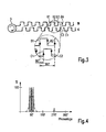
- Fig. 3 shows schematically the detection of the phase position between pulses of two tracks, both tracks B and C have the same number of pulses per revolution.
- the detected phase angle is used to the functionality of the rotary encoder 5 to to verify.
- the relative phase between the pulses of the Lane B and Lane C are using a so-called Four quadrants evaluation determined.
- Under the Four-quadrant evaluation is the evaluation of the rising edge B1 of the signal of the track B (see enlarged section) to the rising edge C1 of the signal the track C, the falling edge B2 of the signal of the track B to the rising edge C1 of the signal of the track C, the falling edge B2 of the signal of the track B to the falling Flank C2 of the signal of the track C, as well as the rising edge B1 of the signal of the track B to the falling edge C2 of the signal the lane C. Thanks to the measured time differences of the different flanks can be the relative Determine the phase position of the two signals to each other.
- the relative phase of the signal C with respect to the signal B determined. In the same way and way you can also the relative phase of the signal B with respect to signal C. The phase positions then differ only by the sign.
- test device 9 Since the test device 9 takes a certain period of time to To evaluate the measured data will be after the acquisition flanks B1, B2 and C1, C2 do not immediately follow the following Pulses with flanks B3, B4 on lane B and the flanks C3, C4 recorded on the track C.
- relative phase of the following pulses over several Revolved revolutions recorded For example, only everyone 20. Pulse of a revolution detected, so you need a total 20 turns to capture all pulses.
- it is at each revolution on the already measured impulse following impulse relative to following pulse of the other track analyzed.
- the detected phase positions are stored in a memory (not shown) of the tester 9 cached so that from the detected phase angles a phase position distribution can be determined in the form of a histogram is issued.
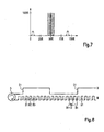
- FIG. 4 shows, by way of example, a histogram showing the Phase position distribution of the rotary pulse generator 5 (see FIG. 1) shows.
- the phase angle is in degrees and on the y-axis the number of detected Phases applied per degree of angle.
- the pulse generator 5 for all pulses of Tracks B and C have a phase angle of 90 ° (vertical Solid line).
- the real case however, has one functioning rotary encoder a phase position distribution, which fits tightly to this ideal phasing (see dashed curve). Is that different? Phase shift distribution significantly from this Ideal phase distribution, it can be based on a lack Close the functionality.
- the histographic Presentation has the advantage that the operator of Device 1 with a look recognizes whether the Phase position distribution still in the permitted range (hatched area). Dodge the Phase shift distribution due to permanent errors such as Wear and tear or soiling of the Rotary encoder from it (dash-dotted Phase position distribution), is from the tester 9 a Warning signal is output or the device 1 is automatically switched off by the control unit 7.
- the track D has a Pulse per revolution.
- this phase position measurement is the Phase offset between the rising edge D1 of the signal the track D and the rising edge B1 of the signal of the track B determined.
- the determination of the pulse length-to-pulse-pause ratio is explained on the track B.
- the measuring principle is that three consecutive flanks B1, B2 and B3 in time be recorded.
- From these three time information determines the Tester 9 then the pulse length to pulse break ratio. Since, as with phase position determination, the Evaluation of the measured times by the test device 9 requires a certain amount of time, all the impulses become one again Turn measured over several revolutions to measure the pulse length to pulse break ratio for all pulses to determine a track. For example, every xth Measure impulse and measured in between two Pulse lying time evaluated.
- FIG. 7 An example of such a histogram is shown in FIG. 7 shown.
- Plotted in percent On the x-axis becomes the pulse length to pulse break ratio Plotted in percent and on the y-axis the number of detected ratios per pulse length to pulse break ratio.
- Plotted in percent On the x-axis the pulse length to pulse break ratio Plotted in percent and on the y-axis the number of detected ratios per pulse length to pulse break ratio.
- Plotted in percent the pulse length to pulse break ratio
- y-axis the number of detected ratios per pulse length to pulse break ratio.
- a vertical line see solid line.
- a real distribution is with a shown dashed line and is close to the ideal Distribution. As long as this distribution is hatched Area, for example, out Manufacturer specifications or empirical values, is, the functionality of the rotary encoder 5 given.
- test device 9 designed so that to check the functionality
- number of pulses per track Rotation is detected. This part of the test procedure will schematically shown with reference to FIG. 8.
- the rotary encoder 5 is one revolution per revolution Number of pulses. Already the lack of an impulse can no longer be accepted for the desired application become. In an incremental data acquisition, in which the number of false pulses added at each revolution, In the case of machines, this leads to the actual value of Setpoint always further away. Is such a faulty Rotary encoder in a labeling machine, for example for position detection, available, so does one Error noticeable by the offset of the label with respect to the target position of the bottles is getting bigger. Therefore plays this measurement in conjunction with the already mentioned Measurements also play an important role.
- the tester of the illustrated embodiment makes it possible
- rotary encoders which in machines on diverse Sites are used on their functioning and to check reliability.
- the meter is the same designed that there are several characteristics of the rotary encoder measures. These include the detection of the phase angle of two pulse-like tracks, the phase of tracks with unequal number of pulses, pulse length to pulse break ratios all pulses of a track, the number of pulses a trace and possibly also the detection of the frequency of the Rotary encoder. These properties can be in any Combination either all or only partially captured.
- the recording can be continuous, in regular Intervals or on request. Another The advantage of the tester is that the results in Form of histograms can be represented, so that one on simple way the quality of the rotary encoder can check.
- Tester As an integral part of a machine or as an an Machine connectable device can also use the Tester be used so that the machine at Detecting a problem of a rotary encoder automatically is switched off or a warning signal is issued.
Landscapes
- Physics & Mathematics (AREA)
- General Physics & Mathematics (AREA)
- Transmission And Conversion Of Sensor Element Output (AREA)
- Gyroscopes (AREA)
- Blow-Moulding Or Thermoforming Of Plastics Or The Like (AREA)
- Investigating Materials By The Use Of Optical Means Adapted For Particular Applications (AREA)
- Sorting Of Articles (AREA)
Priority Applications (1)
| Application Number | Priority Date | Filing Date | Title |
|---|---|---|---|
| SI200531508T SI1593971T1 (sl) | 2004-05-04 | 2005-05-03 | Naprava in postopek za preverjanje funkcijske učinkovitosti vrtilnega dajalnika impulzov |
Applications Claiming Priority (2)
| Application Number | Priority Date | Filing Date | Title |
|---|---|---|---|
| DE102004021928A DE102004021928A1 (de) | 2004-05-04 | 2004-05-04 | Prüfvorrichtung und Verfahren zur Prüfung der Funktionstüchtigkeit eines Drehimpulsgebers |
| DE102004021928 | 2004-05-04 |
Publications (3)
| Publication Number | Publication Date |
|---|---|
| EP1593971A2 true EP1593971A2 (fr) | 2005-11-09 |
| EP1593971A3 EP1593971A3 (fr) | 2006-01-18 |
| EP1593971B1 EP1593971B1 (fr) | 2012-02-15 |
Family
ID=34936073
Family Applications (1)
| Application Number | Title | Priority Date | Filing Date |
|---|---|---|---|
| EP05009665A Not-in-force EP1593971B1 (fr) | 2004-05-04 | 2005-05-03 | Dispositif et méthode pour vérifier le fonctionnement d'un codeur angulaire |
Country Status (5)
| Country | Link |
|---|---|
| EP (1) | EP1593971B1 (fr) |
| AT (1) | ATE545868T1 (fr) |
| DE (1) | DE102004021928A1 (fr) |
| ES (1) | ES2379051T3 (fr) |
| SI (1) | SI1593971T1 (fr) |
Cited By (3)
| Publication number | Priority date | Publication date | Assignee | Title |
|---|---|---|---|---|
| WO2010040512A1 (fr) * | 2008-10-07 | 2010-04-15 | Khs Ag | Procédé de test pour dispositif de contrôle, en particulier pour dispositif de contrôle de position d’étiquettes |
| CN113049851A (zh) * | 2021-03-11 | 2021-06-29 | 江西湛蓝再生资源回收利用有限责任公司 | 一种预清洁的风速计检测装置 |
| EP3865827A1 (fr) * | 2020-02-14 | 2021-08-18 | Sick Ag | Dispositif de détermination de la position, de la longueur ou de l'angle |
Families Citing this family (4)
| Publication number | Priority date | Publication date | Assignee | Title |
|---|---|---|---|---|
| DE202008004480U1 (de) | 2008-04-02 | 2009-08-13 | Krones Ag | Halteeinrichtung für Drehimpulsgeber |
| DE102008046172B4 (de) | 2008-09-06 | 2022-05-05 | Krones Aktiengesellschaft | Vorrichtung und Verfahren zur Überwachung des Behältertransports bei einer Fördereinrichtung für Behälter und/oder Gebinde |
| CN101833049B (zh) | 2009-02-09 | 2014-01-15 | 富士电机株式会社 | 异常监视装置 |
| FR3090456B1 (fr) | 2018-12-19 | 2020-11-27 | Sidel Participations | Ligne de production de récipients controlée par un dispositif de détermination de position |
Citations (5)
| Publication number | Priority date | Publication date | Assignee | Title |
|---|---|---|---|---|
| DE3511444A1 (de) | 1984-09-03 | 1986-03-13 | Veb Kombinat Medizin- Und Labortechnik Leipzig, Ddr 7033 Leipzig | Schaltungsanordnung zur zuverlaessigkeitsueberwachung von drehzahlimpulsen |
| DE3434608A1 (de) | 1984-09-18 | 1986-03-27 | Siemens AG, 1000 Berlin und 8000 München | Wegmesseinrichtung |
| WO1990004287A1 (fr) | 1988-10-05 | 1990-04-19 | Siemens Aktiengesellschaft | Procede et dispositif de controle de defaillances de signaux de synchronisation |
| US5502376A (en) | 1994-05-24 | 1996-03-26 | Avtron Manufacturing, Inc. | Apparatus for controlling the duty cycle of a pulse generator |
| JPH09264762A (ja) | 1996-03-28 | 1997-10-07 | Jidosha Denki Kogyo Co Ltd | エンコーダの検査装置 |
Family Cites Families (12)
| Publication number | Priority date | Publication date | Assignee | Title |
|---|---|---|---|---|
| DE2022151C3 (de) * | 1970-04-25 | 1978-06-01 | Dr. Johannes Heidenhain Gmbh, 8225 Traunreut | Verfahren und Anordnung zur Fehlervermeidung bei inkrementalen Meßsystemen |
| DE3005149A1 (de) * | 1980-02-12 | 1981-08-20 | Brown, Boveri & Cie Ag, 6800 Mannheim | Verfahren zur ueberwachung von impulsfolgen |
| DE3438358A1 (de) * | 1984-10-19 | 1986-04-30 | Krones Ag Hermann Kronseder Maschinenfabrik, 8402 Neutraubling | Verfahren und vorrichtung zum melden eines staus auf einem gefaessfoerderer |
| DE3726260A1 (de) * | 1987-08-07 | 1989-02-16 | Heidenhain Gmbh Dr Johannes | Positionsmesseinrichtung mit mehreren abtaststellen |
| DE3909373A1 (de) * | 1989-03-22 | 1990-09-27 | Kronseder Maschf Krones | Vorrichtung zum zufuehren von gefaessen zu einer behandlungsmaschine |
| DE4227113A1 (de) * | 1992-08-17 | 1994-02-24 | Bosch Gmbh Robert | Verfahren zur Fehlererkennung bei der Auswertung der Ausgangssignale eines Drehzahlsensors |
| FR2696233B1 (fr) * | 1992-09-25 | 1994-10-28 | Valeo Electronique | Capteur incrémental à signalisation de défaillance. |
| DE4311103A1 (de) * | 1993-04-05 | 1994-10-06 | Komi Koppelberg & Migl Kg | Verfahren und Vorrichtung zum Erkennen von Fehlern bei Glaskörpern |
| DE19602359A1 (de) * | 1996-01-24 | 1997-07-31 | Teves Gmbh Alfred | Verfahren und Schaltungsanordnung zur Überwachung eines Drehzahlsensors |
| DE19613884B4 (de) * | 1996-04-06 | 2004-09-23 | Dr. Johannes Heidenhain Gmbh | Verfahren zur Übertragung von Informationen und hierzu geeignete Vorrichtung |
| DE19749791A1 (de) * | 1997-11-11 | 1999-05-12 | Wabco Gmbh | Auswerteverfahren für ein Ausgangssignal einer eine zyklische Bewegung abtastenden Sensoreinrichtung |
| DE10218332B4 (de) * | 2002-04-10 | 2005-06-16 | rotec GmbH Prüfsysteme für den Maschinenbau | Verfahren zur Analyse von Schwingungen rotierender oder oszillierender Teile |
-
2004
- 2004-05-04 DE DE102004021928A patent/DE102004021928A1/de not_active Ceased
-
2005
- 2005-05-03 EP EP05009665A patent/EP1593971B1/fr not_active Not-in-force
- 2005-05-03 AT AT05009665T patent/ATE545868T1/de active
- 2005-05-03 SI SI200531508T patent/SI1593971T1/sl unknown
- 2005-05-03 ES ES05009665T patent/ES2379051T3/es active Active
Patent Citations (5)
| Publication number | Priority date | Publication date | Assignee | Title |
|---|---|---|---|---|
| DE3511444A1 (de) | 1984-09-03 | 1986-03-13 | Veb Kombinat Medizin- Und Labortechnik Leipzig, Ddr 7033 Leipzig | Schaltungsanordnung zur zuverlaessigkeitsueberwachung von drehzahlimpulsen |
| DE3434608A1 (de) | 1984-09-18 | 1986-03-27 | Siemens AG, 1000 Berlin und 8000 München | Wegmesseinrichtung |
| WO1990004287A1 (fr) | 1988-10-05 | 1990-04-19 | Siemens Aktiengesellschaft | Procede et dispositif de controle de defaillances de signaux de synchronisation |
| US5502376A (en) | 1994-05-24 | 1996-03-26 | Avtron Manufacturing, Inc. | Apparatus for controlling the duty cycle of a pulse generator |
| JPH09264762A (ja) | 1996-03-28 | 1997-10-07 | Jidosha Denki Kogyo Co Ltd | エンコーダの検査装置 |
Cited By (5)
| Publication number | Priority date | Publication date | Assignee | Title |
|---|---|---|---|---|
| WO2010040512A1 (fr) * | 2008-10-07 | 2010-04-15 | Khs Ag | Procédé de test pour dispositif de contrôle, en particulier pour dispositif de contrôle de position d’étiquettes |
| US8711350B2 (en) | 2008-10-07 | 2014-04-29 | Khs Gmbh | Test method for inspection device, particularly for label seating inspection device |
| EP3865827A1 (fr) * | 2020-02-14 | 2021-08-18 | Sick Ag | Dispositif de détermination de la position, de la longueur ou de l'angle |
| CN113049851A (zh) * | 2021-03-11 | 2021-06-29 | 江西湛蓝再生资源回收利用有限责任公司 | 一种预清洁的风速计检测装置 |
| CN113049851B (zh) * | 2021-03-11 | 2022-11-01 | 蒙东协合扎鲁特旗风力发电有限公司 | 一种预清洁的风速计检测装置 |
Also Published As
| Publication number | Publication date |
|---|---|
| EP1593971A3 (fr) | 2006-01-18 |
| ES2379051T3 (es) | 2012-04-20 |
| ATE545868T1 (de) | 2012-03-15 |
| DE102004021928A1 (de) | 2005-12-01 |
| EP1593971B1 (fr) | 2012-02-15 |
| SI1593971T1 (sl) | 2012-05-31 |
Similar Documents
| Publication | Publication Date | Title |
|---|---|---|
| EP1593971B1 (fr) | Dispositif et méthode pour vérifier le fonctionnement d'un codeur angulaire | |
| DE3880299T2 (de) | Verfahren zum Messen von Zahnradfehlern durch Abwälzen und Maschine dafür. | |
| DE602005002763T2 (de) | Kodierer und Steuervorrichtung für Motor | |
| DE112006003860B4 (de) | Drehgeber-Frequenzanalyse | |
| DE112006003859T5 (de) | Drehgeber-Frequenzanalyse | |
| DE19628765B4 (de) | Verfahren und Vorrichtung zur Positionsbestimmung von nicht-geradlinig bewegten, insbesondere rotierenden Maschinenteilen | |
| DE102010012858B4 (de) | Vorrichtung und Verfahren zur rotatorischen Ausrichtung eines Tubenkopfes relativ zu einem Tubenkörper | |
| DE60019399T2 (de) | Optische messeinrichtung zur messung von objekten auf maschinen | |
| DE3732444C2 (de) | Kompensation von Prüfzahnradfehlern | |
| DE19613884A1 (de) | Verfahren zur Übertragung von Informationen und hierzu geeignete Vorrichtung | |
| DE3823478C2 (fr) | ||
| DE102007033009A1 (de) | Verfahren und Vorrichtung zur Übertragung von Signalen von einer Positionsmesseinrichtung zu einer Auswerteeinheit | |
| DE102012014493B4 (de) | Verfahren und Vorrichtung zur redundanten Erkennung einer Drehrichtung | |
| DE10335862B4 (de) | Verfahren zum Kalibrieren eines inkrementalen Winkelgebers an einem rotierenden Bauteil | |
| DE3815530C2 (fr) | ||
| WO1998050772A1 (fr) | Dispositif pour la mesure complete des dentures d'engrenages, y compris de la topographie des flancs des dents | |
| EP3607314A1 (fr) | Dispositif et procédé d'essai non destructif pour un composant | |
| DE10312208B3 (de) | Verfahren und Vorrichtung zum Erfassen einer Drehzahl, insbesondere einer Raddrehzahl eines Kraftfahrzeugs | |
| DE4009749C2 (fr) | ||
| DE69400786T2 (de) | Verfahren und Vorrichtung zum Überwachen von Signalen von Wandlern und optischen Encodern | |
| EP0294674B1 (fr) | Procédé et dispositif pour la surveillance des courroies tangentielles d'une machine pour la production de fils tournés ou retordus | |
| WO2013026434A1 (fr) | Capteur de déplacement incrémentiel | |
| EP3865827B1 (fr) | Dispositif de détermination de la position, de la longueur ou de l'angle | |
| AT510820B1 (de) | Korrekturverfahren für drehgeber | |
| DE2210204B2 (de) | Optisches KartenlesegeräL |
Legal Events
| Date | Code | Title | Description |
|---|---|---|---|
| PUAI | Public reference made under article 153(3) epc to a published international application that has entered the european phase |
Free format text: ORIGINAL CODE: 0009012 |
|
| AK | Designated contracting states |
Kind code of ref document: A2 Designated state(s): AT BE BG CH CY CZ DE DK EE ES FI FR GB GR HU IE IS IT LI LT LU MC NL PL PT RO SE SI SK TR |
|
| AX | Request for extension of the european patent |
Extension state: AL BA HR LV MK YU |
|
| PUAL | Search report despatched |
Free format text: ORIGINAL CODE: 0009013 |
|
| RIC1 | Information provided on ipc code assigned before grant |
Ipc: B65C 9/06 19680901ALI20051124BHEP Ipc: G01P 21/02 19680901AFI20050824BHEP Ipc: G01D 5/245 19680901ALI20051124BHEP Ipc: G01P 3/487 19800101ALI20051124BHEP Ipc: B65G 43/10 19680901ALI20051124BHEP Ipc: G01P 13/04 19800101ALI20051124BHEP Ipc: G01D 5/244 19680901ALI20051124BHEP |
|
| AK | Designated contracting states |
Kind code of ref document: A3 Designated state(s): AT BE BG CH CY CZ DE DK EE ES FI FR GB GR HU IE IS IT LI LT LU MC NL PL PT RO SE SI SK TR |
|
| AX | Request for extension of the european patent |
Extension state: AL BA HR LV MK YU |
|
| 17P | Request for examination filed |
Effective date: 20060127 |
|
| AKX | Designation fees paid |
Designated state(s): AT BE BG CH CY CZ DE DK EE ES FI FR GB GR HU IE IS IT LI LT LU MC NL PL PT RO SE SI SK TR |
|
| GRAP | Despatch of communication of intention to grant a patent |
Free format text: ORIGINAL CODE: EPIDOSNIGR1 |
|
| GRAS | Grant fee paid |
Free format text: ORIGINAL CODE: EPIDOSNIGR3 |
|
| GRAA | (expected) grant |
Free format text: ORIGINAL CODE: 0009210 |
|
| AK | Designated contracting states |
Kind code of ref document: B1 Designated state(s): AT BE BG CH CY CZ DE DK EE ES FI FR GB GR HU IE IS IT LI LT LU MC NL PL PT RO SE SI SK TR |
|
| REG | Reference to a national code |
Ref country code: CH Ref legal event code: NV Representative=s name: BOVARD AG Ref country code: CH Ref legal event code: EP Ref country code: GB Ref legal event code: FG4D Free format text: NOT ENGLISH |
|
| REG | Reference to a national code |
Ref country code: NL Ref legal event code: T3 Ref country code: IE Ref legal event code: FG4D Free format text: LANGUAGE OF EP DOCUMENT: GERMAN |
|
| REG | Reference to a national code |
Ref country code: AT Ref legal event code: REF Ref document number: 545868 Country of ref document: AT Kind code of ref document: T Effective date: 20120315 |
|
| REG | Reference to a national code |
Ref country code: DE Ref legal event code: R096 Ref document number: 502005012437 Country of ref document: DE Effective date: 20120405 |
|
| REG | Reference to a national code |
Ref country code: ES Ref legal event code: FG2A Ref document number: 2379051 Country of ref document: ES Kind code of ref document: T3 Effective date: 20120420 |
|
| LTIE | Lt: invalidation of european patent or patent extension |
Effective date: 20120215 |
|
| PG25 | Lapsed in a contracting state [announced via postgrant information from national office to epo] |
Ref country code: LT Free format text: LAPSE BECAUSE OF FAILURE TO SUBMIT A TRANSLATION OF THE DESCRIPTION OR TO PAY THE FEE WITHIN THE PRESCRIBED TIME-LIMIT Effective date: 20120215 Ref country code: IS Free format text: LAPSE BECAUSE OF FAILURE TO SUBMIT A TRANSLATION OF THE DESCRIPTION OR TO PAY THE FEE WITHIN THE PRESCRIBED TIME-LIMIT Effective date: 20120615 |
|
| PG25 | Lapsed in a contracting state [announced via postgrant information from national office to epo] |
Ref country code: GR Free format text: LAPSE BECAUSE OF FAILURE TO SUBMIT A TRANSLATION OF THE DESCRIPTION OR TO PAY THE FEE WITHIN THE PRESCRIBED TIME-LIMIT Effective date: 20120516 Ref country code: FI Free format text: LAPSE BECAUSE OF FAILURE TO SUBMIT A TRANSLATION OF THE DESCRIPTION OR TO PAY THE FEE WITHIN THE PRESCRIBED TIME-LIMIT Effective date: 20120215 Ref country code: PL Free format text: LAPSE BECAUSE OF FAILURE TO SUBMIT A TRANSLATION OF THE DESCRIPTION OR TO PAY THE FEE WITHIN THE PRESCRIBED TIME-LIMIT Effective date: 20120215 Ref country code: PT Free format text: LAPSE BECAUSE OF FAILURE TO SUBMIT A TRANSLATION OF THE DESCRIPTION OR TO PAY THE FEE WITHIN THE PRESCRIBED TIME-LIMIT Effective date: 20120615 |
|
| REG | Reference to a national code |
Ref country code: IE Ref legal event code: FD4D |
|
| PG25 | Lapsed in a contracting state [announced via postgrant information from national office to epo] |
Ref country code: CY Free format text: LAPSE BECAUSE OF FAILURE TO SUBMIT A TRANSLATION OF THE DESCRIPTION OR TO PAY THE FEE WITHIN THE PRESCRIBED TIME-LIMIT Effective date: 20120215 |
|
| PG25 | Lapsed in a contracting state [announced via postgrant information from national office to epo] |
Ref country code: SE Free format text: LAPSE BECAUSE OF FAILURE TO SUBMIT A TRANSLATION OF THE DESCRIPTION OR TO PAY THE FEE WITHIN THE PRESCRIBED TIME-LIMIT Effective date: 20120215 Ref country code: IE Free format text: LAPSE BECAUSE OF FAILURE TO SUBMIT A TRANSLATION OF THE DESCRIPTION OR TO PAY THE FEE WITHIN THE PRESCRIBED TIME-LIMIT Effective date: 20120215 Ref country code: DK Free format text: LAPSE BECAUSE OF FAILURE TO SUBMIT A TRANSLATION OF THE DESCRIPTION OR TO PAY THE FEE WITHIN THE PRESCRIBED TIME-LIMIT Effective date: 20120215 Ref country code: RO Free format text: LAPSE BECAUSE OF FAILURE TO SUBMIT A TRANSLATION OF THE DESCRIPTION OR TO PAY THE FEE WITHIN THE PRESCRIBED TIME-LIMIT Effective date: 20120215 Ref country code: CZ Free format text: LAPSE BECAUSE OF FAILURE TO SUBMIT A TRANSLATION OF THE DESCRIPTION OR TO PAY THE FEE WITHIN THE PRESCRIBED TIME-LIMIT Effective date: 20120215 Ref country code: EE Free format text: LAPSE BECAUSE OF FAILURE TO SUBMIT A TRANSLATION OF THE DESCRIPTION OR TO PAY THE FEE WITHIN THE PRESCRIBED TIME-LIMIT Effective date: 20120215 |
|
| PG25 | Lapsed in a contracting state [announced via postgrant information from national office to epo] |
Ref country code: SK Free format text: LAPSE BECAUSE OF FAILURE TO SUBMIT A TRANSLATION OF THE DESCRIPTION OR TO PAY THE FEE WITHIN THE PRESCRIBED TIME-LIMIT Effective date: 20120215 |
|
| PLBE | No opposition filed within time limit |
Free format text: ORIGINAL CODE: 0009261 |
|
| STAA | Information on the status of an ep patent application or granted ep patent |
Free format text: STATUS: NO OPPOSITION FILED WITHIN TIME LIMIT |
|
| PG25 | Lapsed in a contracting state [announced via postgrant information from national office to epo] |
Ref country code: MC Free format text: LAPSE BECAUSE OF NON-PAYMENT OF DUE FEES Effective date: 20120531 |
|
| 26N | No opposition filed |
Effective date: 20121116 |
|
| REG | Reference to a national code |
Ref country code: DE Ref legal event code: R097 Ref document number: 502005012437 Country of ref document: DE Effective date: 20121116 |
|
| PG25 | Lapsed in a contracting state [announced via postgrant information from national office to epo] |
Ref country code: BG Free format text: LAPSE BECAUSE OF FAILURE TO SUBMIT A TRANSLATION OF THE DESCRIPTION OR TO PAY THE FEE WITHIN THE PRESCRIBED TIME-LIMIT Effective date: 20120515 |
|
| PG25 | Lapsed in a contracting state [announced via postgrant information from national office to epo] |
Ref country code: TR Free format text: LAPSE BECAUSE OF FAILURE TO SUBMIT A TRANSLATION OF THE DESCRIPTION OR TO PAY THE FEE WITHIN THE PRESCRIBED TIME-LIMIT Effective date: 20120215 |
|
| PG25 | Lapsed in a contracting state [announced via postgrant information from national office to epo] |
Ref country code: LU Free format text: LAPSE BECAUSE OF NON-PAYMENT OF DUE FEES Effective date: 20120503 |
|
| PG25 | Lapsed in a contracting state [announced via postgrant information from national office to epo] |
Ref country code: HU Free format text: LAPSE BECAUSE OF FAILURE TO SUBMIT A TRANSLATION OF THE DESCRIPTION OR TO PAY THE FEE WITHIN THE PRESCRIBED TIME-LIMIT Effective date: 20050503 |
|
| REG | Reference to a national code |
Ref country code: FR Ref legal event code: PLFP Year of fee payment: 11 |
|
| PGFP | Annual fee paid to national office [announced via postgrant information from national office to epo] |
Ref country code: GB Payment date: 20150429 Year of fee payment: 11 Ref country code: ES Payment date: 20150413 Year of fee payment: 11 Ref country code: SI Payment date: 20150408 Year of fee payment: 11 Ref country code: CH Payment date: 20150512 Year of fee payment: 11 Ref country code: DE Payment date: 20150428 Year of fee payment: 11 |
|
| PGFP | Annual fee paid to national office [announced via postgrant information from national office to epo] |
Ref country code: IT Payment date: 20150515 Year of fee payment: 11 Ref country code: BE Payment date: 20150514 Year of fee payment: 11 Ref country code: AT Payment date: 20150427 Year of fee payment: 11 Ref country code: FR Payment date: 20150508 Year of fee payment: 11 Ref country code: NL Payment date: 20150510 Year of fee payment: 11 |
|
| PG25 | Lapsed in a contracting state [announced via postgrant information from national office to epo] |
Ref country code: BE Free format text: LAPSE BECAUSE OF NON-PAYMENT OF DUE FEES Effective date: 20160531 |
|
| REG | Reference to a national code |
Ref country code: DE Ref legal event code: R119 Ref document number: 502005012437 Country of ref document: DE |
|
| REG | Reference to a national code |
Ref country code: CH Ref legal event code: PL |
|
| REG | Reference to a national code |
Ref country code: NL Ref legal event code: MM Effective date: 20160601 |
|
| REG | Reference to a national code |
Ref country code: AT Ref legal event code: MM01 Ref document number: 545868 Country of ref document: AT Kind code of ref document: T Effective date: 20160503 |
|
| GBPC | Gb: european patent ceased through non-payment of renewal fee |
Effective date: 20160503 |
|
| PG25 | Lapsed in a contracting state [announced via postgrant information from national office to epo] |
Ref country code: CH Free format text: LAPSE BECAUSE OF NON-PAYMENT OF DUE FEES Effective date: 20160531 Ref country code: LI Free format text: LAPSE BECAUSE OF NON-PAYMENT OF DUE FEES Effective date: 20160531 |
|
| PG25 | Lapsed in a contracting state [announced via postgrant information from national office to epo] |
Ref country code: IT Free format text: LAPSE BECAUSE OF NON-PAYMENT OF DUE FEES Effective date: 20160503 Ref country code: AT Free format text: LAPSE BECAUSE OF NON-PAYMENT OF DUE FEES Effective date: 20160503 Ref country code: NL Free format text: LAPSE BECAUSE OF NON-PAYMENT OF DUE FEES Effective date: 20160601 |
|
| REG | Reference to a national code |
Ref country code: FR Ref legal event code: ST Effective date: 20170131 |
|
| REG | Reference to a national code |
Ref country code: SI Ref legal event code: KO00 Effective date: 20170216 |
|
| PG25 | Lapsed in a contracting state [announced via postgrant information from national office to epo] |
Ref country code: DE Free format text: LAPSE BECAUSE OF NON-PAYMENT OF DUE FEES Effective date: 20161201 Ref country code: FR Free format text: LAPSE BECAUSE OF NON-PAYMENT OF DUE FEES Effective date: 20160531 |
|
| PG25 | Lapsed in a contracting state [announced via postgrant information from national office to epo] |
Ref country code: SI Free format text: LAPSE BECAUSE OF NON-PAYMENT OF DUE FEES Effective date: 20160504 Ref country code: GB Free format text: LAPSE BECAUSE OF NON-PAYMENT OF DUE FEES Effective date: 20160503 |
|
| PG25 | Lapsed in a contracting state [announced via postgrant information from national office to epo] |
Ref country code: ES Free format text: LAPSE BECAUSE OF NON-PAYMENT OF DUE FEES Effective date: 20160504 |
|
| REG | Reference to a national code |
Ref country code: ES Ref legal event code: FD2A Effective date: 20181204 |