EP1593886A1 - Dichtungsanordnung mit Sensor - Google Patents
Dichtungsanordnung mit Sensor Download PDFInfo
- Publication number
- EP1593886A1 EP1593886A1 EP05007020A EP05007020A EP1593886A1 EP 1593886 A1 EP1593886 A1 EP 1593886A1 EP 05007020 A EP05007020 A EP 05007020A EP 05007020 A EP05007020 A EP 05007020A EP 1593886 A1 EP1593886 A1 EP 1593886A1
- Authority
- EP
- European Patent Office
- Prior art keywords
- sealed
- sealing arrangement
- arrangement according
- sealing
- seal
- Prior art date
- Legal status (The legal status is an assumption and is not a legal conclusion. Google has not performed a legal analysis and makes no representation as to the accuracy of the status listed.)
- Granted
Links
Images





Classifications
-
- F—MECHANICAL ENGINEERING; LIGHTING; HEATING; WEAPONS; BLASTING
- F16—ENGINEERING ELEMENTS AND UNITS; GENERAL MEASURES FOR PRODUCING AND MAINTAINING EFFECTIVE FUNCTIONING OF MACHINES OR INSTALLATIONS; THERMAL INSULATION IN GENERAL
- F16J—PISTONS; CYLINDERS; SEALINGS
- F16J15/00—Sealings
- F16J15/16—Sealings between relatively-moving surfaces
- F16J15/32—Sealings between relatively-moving surfaces with elastic sealings, e.g. O-rings
- F16J15/3296—Arrangements for monitoring the condition or operation of elastic sealings; Arrangements for control of elastic sealings, e.g. of their geometry or stiffness
-
- F—MECHANICAL ENGINEERING; LIGHTING; HEATING; WEAPONS; BLASTING
- F16—ENGINEERING ELEMENTS AND UNITS; GENERAL MEASURES FOR PRODUCING AND MAINTAINING EFFECTIVE FUNCTIONING OF MACHINES OR INSTALLATIONS; THERMAL INSULATION IN GENERAL
- F16J—PISTONS; CYLINDERS; SEALINGS
- F16J15/00—Sealings
- F16J15/16—Sealings between relatively-moving surfaces
- F16J15/32—Sealings between relatively-moving surfaces with elastic sealings, e.g. O-rings
- F16J15/3204—Sealings between relatively-moving surfaces with elastic sealings, e.g. O-rings with at least one lip
- F16J15/3228—Sealings between relatively-moving surfaces with elastic sealings, e.g. O-rings with at least one lip formed by deforming a flat ring
-
- F—MECHANICAL ENGINEERING; LIGHTING; HEATING; WEAPONS; BLASTING
- F16—ENGINEERING ELEMENTS AND UNITS; GENERAL MEASURES FOR PRODUCING AND MAINTAINING EFFECTIVE FUNCTIONING OF MACHINES OR INSTALLATIONS; THERMAL INSULATION IN GENERAL
- F16J—PISTONS; CYLINDERS; SEALINGS
- F16J15/00—Sealings
- F16J15/16—Sealings between relatively-moving surfaces
- F16J15/32—Sealings between relatively-moving surfaces with elastic sealings, e.g. O-rings
- F16J15/324—Arrangements for lubrication or cooling of the sealing itself
-
- G—PHYSICS
- G01—MEASURING; TESTING
- G01P—MEASURING LINEAR OR ANGULAR SPEED, ACCELERATION, DECELERATION, OR SHOCK; INDICATING PRESENCE, ABSENCE, OR DIRECTION, OF MOVEMENT
- G01P3/00—Measuring linear or angular speed; Measuring differences of linear or angular speeds
- G01P3/42—Devices characterised by the use of electric or magnetic means
- G01P3/44—Devices characterised by the use of electric or magnetic means for measuring angular speed
- G01P3/443—Devices characterised by the use of electric or magnetic means for measuring angular speed mounted in bearings
Definitions
- the invention relates to a seal assembly comprising a seal with a sealing lip and a sensor device.
- Sealing arrangements with a seal and a sensor device are known from DE 199 51 340.
- the sensor of the previously known Sealing arrangement serves primarily to detect the speed of a to be sealed shaft.
- the invention is based on the object, a seal assembly with a To develop sensor technology that is suitable for certain parameters of the To monitor lubricant.
- a sealing arrangement comprising a seal with a sealing lip and a sensor device with a in one to be sealed space projecting tongue, the tongue during the intended use with medium to be sealed can be acted upon.
- the parameters to be monitored of the lubricant can constantly recorded and evaluated.
- a retaining device for be sealed medium to be projected into the Meßzunge.
- the Retaining device fills at the beginning of the intended Use with medium to be sealed. Because the tongue in the Retaining device dips, the tongue is during operation constantly wetted with the medium.
- the volume of the retention device can to the requirements of the measuring tongue and the parameter to be measured be matched. Because the retainer is constantly in operation is wetted with the medium, also measured values can be detected, which is a require longer measurement time.
- the retainer may be attached to the seal be.
- the retainer can thereby inexpensively and easily on the Seal to be molded.
- the retaining device can, for example be made in one piece with the support body of the seal.
- the retaining device may have a retaining lip, which is a at least partially encloses the sealed shaft. This forms a large reservoir, which during operation with the sealed Medium fills, which is beneficial to the accuracy of the measurement tongue effect.
- the retaining lip can surround the shaft at least partially touching.
- the retainer thereby forms an upstream seal, wherein the restraint during its intended use with is filled medium to be sealed.
- the retaining device on the Be attached sensor device can then be mounted as a prefabricated unit in a gasket.
- the Unit can be mounted in standard gaskets.
- the seals can be prepared easily and inexpensively for receiving the unit become.
- the retaining device may have a drip hole.
- the Drip hole is the medium to be sealed during operation constantly replaced, or the retainer is at the beginning of the operation new filled. This ensures that constantly a different subset of the Medium is tested. The measurement result can then be applied to the entire medium be transmitted.
- the tongue can be used as a transmitter to record the age of the be formed medium to be sealed. By capturing certain Parameters such as the Total Base Number can be used to alter the age of the tongue Be determined medium.
- the determination of the oil age allows the Introduction of variable oil change intervals, which vary according to the actual Arrange the life of the oil.
- the tongue can be used as a transmitter to detect the temperature and / or the pressure and / or the filling quantity of the medium to be sealed be educated. This can be important data for the operation of the be sealed medium to be sealed. It can be timely warning be transmitted when temperature, pressure and capacity outside the Limits are.
- the seal may have a support body, wherein the support body a Can have recess in which the sensor device is arranged. The allows easy and cost-effective attachment of the Sensor device.
- a cleaning device may be arranged, comprising a cleaning line and a cleaning nozzle, wherein the Cleaning nozzle is directed to the measuring tongue.
- Cleaning device can remove dirt from the tongue which affect the measurement accuracy of the sensor device can.
- a cleaning agent can compressed air, new lubricant and / or lubricant-compatible solvent can be used.
- It may be a housing closure cover with a sealing arrangement be provided, wherein the support body as a sealing flange with a recess may be formed, wherein the sensor device in the recess is arranged.
- the stiffening flange of plastic injection molding be formed. Reinforcement flanges made of plastic injection molding are simple and inexpensive to produce.
- the stiffening flange of a be formed metallic material.
- Metallic stiffening bottle Materials have a high strength.
- Figure 1 shows a seal assembly 1 with a seal 13, one in the to be sealed space 3 bulging sealing lip 14 has.
- the sealing lip 14 and a static seal 15 for sealing the seal 13 against a housing 16 are attached to a support body 9.
- the support body 9 has a recess 10 in which the sensor device 2 is attached.
- the Measuring tongue 4 of the sensor device 2 protrudes into the space to be sealed 3.
- Die Sensor device 2 is used as a transmitter for determining the age of formed medium to be sealed and may alternatively also as Measuring sensors are used to determine temperature, pressure and filling quantity.
- On the support body 9 is a retaining device 5 with a retaining lip. 7 fastened, wherein the retaining lip 7, the sealed shaft 8 partially, in this embodiment half encloses.
- the tongue 4 protrudes into the through Retaining lip formed space and is in operation with the wetted medium wetted.
- the retaining device 5 has at the lowest point a drip hole 6, through which the medium to be sealed dripped and thereby constantly renewed during operation.
- the Sensor device 2 is non-destructively detachable with the seal assembly. 1 connected and removable to the environment side. For that, the Sensor device 2 by means of a bayonet or snap closure in the Seal assembly 1 to be attached. Other mounting options are Pressing or gluing.
- FIG 2 shows a seal assembly according to Figure 1, wherein the Retaining device 5 in this embodiment as an annular component is formed and the seal 13 encloses the outer peripheral side.
- the Retaining device 5 has a static seal 15 which is used for sealing is provided opposite the housing 16.
- the retaining lip 7 of Retaining device 5 encloses the sealed shaft 8 partially touching.
- Figure 3 shows a seal assembly 1 according to Figure 2, wherein the sealing lip 14 of the seal 13 is arched against the space to be sealed 3.
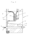
- FIG. 4 shows a housing closure cover 17 with a stiffening flange 12 made of light metal injection molding and a sealing flange 18 made of tough Material.
- a seal 13 is on the inner peripheral side arranged a sealing lip 14 which bulges in the space to be sealed 3 is.
- the stiffening flange 12 has a recess 10 in which the Sensor device 2 is attached.
- the measuring tongue 4 of the sensor device 2 protrudes into the space to be sealed 3.
- a Retaining device 5 attached in the form of a pan. By the Retaining device 5, the Meßzunge 4 during operation constantly with wetted medium wetted.
- FIG. 5 shows a housing closure cover 17 with a stiffening flange 12 made of light metal and a sealing flange 18 made of plastic injection.
- a seal 13 on the inner peripheral side with a Sealing lip 14 arranged opposite to the space to be sealed. 3 is arched.
- the measuring tongue 4 is in a recess 10 of the Sealing flange 18 attached.
- the measuring tongue 4 of the sensor device 2 projects in the space to be sealed 3.
- To the sealing flange 18 is a Retaining device formed, which forms a space in which the measuring tongue 4 protrudes and in the medium to be sealed collects which Wetted tongue.
- the retaining device 5 has at the lowest point Abtropfbohrung 6, through which the medium to be sealed drips and thereby constantly renewed during operation.
- the Housing closure cover 17 has in addition to the sensor device 2 a Device 19, which serves to detect the speed.
- FIG. 6 shows a housing closure cover 17 with a sealing flange 18 drawn sheet metal.
- a seal 13 with a sealing lip 14 is arranged.
- the Housing closure cover 17 has a recess 10 in which the Sensor device 2 is attached.
- the measuring tongue 4 of the sensor device 2 protrudes into the space to be sealed 3.
- a Retaining device 5 attached in the form of a pan. By the Retaining device 5, the Meßzunge 4 during operation constantly with wetted medium wetted.
- FIG. 7 shows the housing closure cover according to FIG. 6 in plan view.
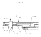
- FIG. 8 shows a housing closure cover 17 with a sealing flange 18 drawn sheet metal.
- a seal 13 with a sealing lip 14 is arranged on the housing closure cover 17 .
- the Housing closure cover 17 has a recess 10 in which the Sensor device 2 is attached.
- the measuring tongue 4 of the sensor device 2 protrudes into the space to be sealed 3 and is during operation with Lubricant applied.
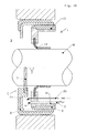
- FIG. 9 shows a sealing arrangement according to FIG. 3.
- the sealing lip 14 of FIG Seal 13 is bulged against the space to be sealed 3.
- a cleaning line 20 integrated in a Cleaning nozzle 21 opens.
- the cleaning nozzle 21 is on the Meßzunge 4th directed.
- a cleaning agent under Be injected pressure may be, for example, air, Lubricant and / or a lubricant-compatible solvent consist.
- FIG. 10 shows a sealing arrangement according to FIG. 3.
- the sealing lip 14 of FIG Seal 13 is bulged against the space to be sealed 3.
- a cleaning line 20 integrated in a cleaning nozzle 21 opens.
- the cleaning nozzle 21 is directed to the measuring tongue 4. at Contamination of the measuring tongue 4 can cause a cleaning agent under pressure be blown.
Landscapes
- Engineering & Computer Science (AREA)
- General Engineering & Computer Science (AREA)
- Mechanical Engineering (AREA)
- Physics & Mathematics (AREA)
- General Physics & Mathematics (AREA)
- Examining Or Testing Airtightness (AREA)
- Transmission And Conversion Of Sensor Element Output (AREA)
- Sealing With Elastic Sealing Lips (AREA)
- Ultra Sonic Daignosis Equipment (AREA)
- Measuring And Recording Apparatus For Diagnosis (AREA)
- Measuring Fluid Pressure (AREA)
- Sealing Of Bearings (AREA)
Abstract
Description
- Fig. 1
- eine Dichtungsanordnung mit einer am Tragkörper befestigten Rückhalteeinrichtung;
- Fig. 2
- eine Dichtungsanordnung mit einer in der abzudichtenden Bohrung befestigten Rückhalteeinrichtung, wobei die Dichtung am Innenumfang des Haftteils der Rückhalteeinrichtung festgelegt ist;
- Fig. 3
- eine Dichtungsanordnung mit einer Dichtlippe, die entgegen des abzudichtenden Raums vorgewölbt ist;
- Fig. 4
- einen Gehäuseverschlussdeckel mit einer am Versteifungsflansch befestigten Sensoreinrichtung;
- Fig. 5
- einen Gehäuseverschlussdeckel mit einer am Dichtflansch befestigten Sensoreinrichtung;
- Fig. 6
- einen Gehäuseverschlussdeckel mit einer am Dichtflansch befestigten Sensoreinrichtung;
- Fig. 7
- den Gehäuseverschlussdeckel gemäß Figur 6 in der Draufsicht;
- Fig. 8
- eine erfindungsgemäße Dichtungsanordnung ohne Rückhalteeinrichtung;
- Fig.9
- eine Dichtungsanordnung mit Sensorik und einer Reinigungseinrichtung;
- Fig.10
- eine Dichtungsanordnung mit Sensorik und einer Reinigungseinrichtung, die in der Dichtung angeordnet ist.
Claims (14)
- Dichtungsanordnung (1), umfassend eine Dichtung (13) mit einer Dichtlippe (14) und eine Sensoreinrichtung (2) mit einer in einen abzudichtenden Raum (3) ragenden Messzunge (4), wobei die Messzunge (4) während der bestimmungsgemäßen Verwendung mit abzudichtendem Medium beaufschlagbar ist.
- Dichtungsanordnung nach Anspruch 1, dadurch gekennzeichnet, dass in dem abzudichtenden Raum (3) eine Rückhalteeinrichtung (5) für abzudichtendes Medium angeordnet ist, in die die Messzunge hineinragt.
- Dichtungsanordnung nach Anspruch 2, dadurch gekennzeichnet, dass die Rückhalteeinrichtung (5) an der Dichtung (13) befestigt ist.
- Dichtungsanordnung nach Anspruch 2 oder 3, dadurch gekennzeichnet, dass die Rückhalteeinrichtung (5) eine Rückhaltelippe (7) aufweist, die eine abzudichtende Welle (8) zumindest teilweise umschließt.
- Dichtungsanordnung nach Anspruch 4, dadurch gekennzeichnet, dass die Rückhaltelippe (7) die Welle (8) zumindest teilweise berührend umschließt.
- Dichtungsanordnung nach Anspruch 2, dadurch gekennzeichnet, dass die Rückhalteeinrichtung (5) an der Sensoreinrichtung (2) befestigt ist.
- Dichtungsanordnung nach einem der Ansprüche 2 bis 6, dadurch gekennzeichnet, dass die Rückhalteeinrichtung (5) eine Abtropfbohrung (6) aufweist.
- Dichtungsanordnung nach einem der Ansprüche 1 bis 7, dadurch gekennzeichnet, dass die Messzunge (4) als Messwertgeber zur Erfassung des Alters des abzudichtenden Mediums ausgebildet ist.
- Dichtungsanordnung nach einem der Ansprüche 1 bis 8, dadurch gekennzeichnet, dass die Messzunge (4) als Messwertgeber zur Erfassung der Temperatur und/oder des Drucks und/oder der Füllmenge des abzudichtenden Mediums ausgebildet ist.
- Dichtungsanordnung nach einem der Ansprüche 1 bis 9, dadurch gekennzeichnet, dass die Dichtung (13) einen Tragkörper (9) aufweist, wobei der Tragkörper (9) eine Ausnehmung (10) aufweist in der die Sensoreinrichtung (2) angeordnet ist.
- Dichtungsanordnung nach einem der Ansprüche 1 bis 10, dadurch gekennzeichnet, dass in der Dichtungsanordnung eine Reinigungseinrichtung angeordnet ist, umfassend eine Reinigungsleitung (20) und eine Reinigungsdüse (21), wobei die Reinigungsdüse (21) auf die Messzunge (4) gerichtet ist.
- Gehäuseverschlussdeckel mit einer Dichtungsanordnung nach einem der Ansprüche 1 bis 11, dadurch gekennzeichnet, dass der Tragkörper (9) als Dichtflansch (12) mit einer Ausnehmung (10) ausgebildet ist, wobei die Sensoreinrichtung (2) in der Ausnehmung (10) angeordnet ist.
- Gehäuseverschlussdeckel nach Anspruch 12, dadurch gekennzeichnet, dass der Dichtflansch (12) aus Kunststoff-Spritzguss gebildet ist.
- Gehäuseverschlussdeckel nach Anspruch 12, dadurch gekennzeichnet, dass der Dichtflansch (12) aus einem metallischen Werkstoff gebildet ist.
Applications Claiming Priority (2)
| Application Number | Priority Date | Filing Date | Title |
|---|---|---|---|
| DE102004023315 | 2004-05-07 | ||
| DE102004023315A DE102004023315A1 (de) | 2004-05-07 | 2004-05-07 | Dichtungsanordnung mit Sensor |
Publications (2)
| Publication Number | Publication Date |
|---|---|
| EP1593886A1 true EP1593886A1 (de) | 2005-11-09 |
| EP1593886B1 EP1593886B1 (de) | 2016-02-17 |
Family
ID=34934622
Family Applications (1)
| Application Number | Title | Priority Date | Filing Date |
|---|---|---|---|
| EP05007020.0A Expired - Lifetime EP1593886B1 (de) | 2004-05-07 | 2005-03-31 | Dichtungsanordnung mit Sensor |
Country Status (6)
| Country | Link |
|---|---|
| US (1) | US20060006601A1 (de) |
| EP (1) | EP1593886B1 (de) |
| JP (1) | JP4250615B2 (de) |
| CA (1) | CA2506165A1 (de) |
| DE (1) | DE102004023315A1 (de) |
| MX (1) | MXPA05004906A (de) |
Cited By (5)
| Publication number | Priority date | Publication date | Assignee | Title |
|---|---|---|---|---|
| WO2008009317A1 (en) * | 2006-07-20 | 2008-01-24 | Carl Freudenberg Kg | Seal |
| EP1965107A1 (de) * | 2007-02-27 | 2008-09-03 | Carl Freudenberg KG | Dichtring |
| EP2037161A1 (de) | 2007-09-17 | 2009-03-18 | Carl Freudenberg KG | Dichtung mit integriertem Sensor und Dichtungsanordnung mit dieser Dichtung |
| WO2015054714A1 (de) * | 2013-10-15 | 2015-04-23 | Ssl-Schwellenwerk Und Steuerungstechnik Linz Gmbh | Verstellbare doppelgurtförderanlage |
| CN106996803A (zh) * | 2016-01-25 | 2017-08-01 | 常州兰翔机械有限责任公司 | 一种长度可调传感器夹具及其工作方法 |
Families Citing this family (11)
| Publication number | Priority date | Publication date | Assignee | Title |
|---|---|---|---|---|
| US7702839B2 (en) * | 2005-04-12 | 2010-04-20 | Nokia Corporation | Memory interface for volatile and non-volatile memory devices |
| US9296467B1 (en) * | 2009-06-09 | 2016-03-29 | The Boeing Company | Pressure test door for use with a fuel tank |
| EP2510264B1 (de) | 2009-12-08 | 2017-08-23 | Aktiebolaget SKF | Mit sensoren ausgestattete dichtungseinheit |
| CN103430001B (zh) | 2011-03-14 | 2017-06-09 | Skf公司 | 密封系统 |
| DE102014223829A1 (de) * | 2014-11-21 | 2016-05-25 | Aktiebolaget Skf | Dichtung sowie Lageranordnung mit der Dichtung |
| FR3028901B1 (fr) * | 2014-11-26 | 2017-04-14 | Skf Ab | Roulement instrumente et procede de fabrication d'un tel roulement instrumente |
| GB2532762A (en) | 2014-11-27 | 2016-06-01 | Skf Ab | Load measurement device and method for determining load |
| GB2532928A (en) * | 2014-11-27 | 2016-06-08 | Skf Ab | Sealing assembly and method for monitoring a sealing assembly |
| GB2532927A (en) | 2014-11-27 | 2016-06-08 | Skf Ab | Sealing assembly and method for monitoring dynamic properties of a sealing assembly |
| CN116026382A (zh) | 2021-10-25 | 2023-04-28 | 斯凯孚公司 | 传感器 |
| CN118066059B (zh) * | 2024-02-19 | 2025-04-18 | 宁波新宏液压有限公司 | 高稳定性液压马达 |
Citations (2)
| Publication number | Priority date | Publication date | Assignee | Title |
|---|---|---|---|---|
| EP0631112A1 (de) * | 1993-06-24 | 1994-12-28 | Firma Carl Freudenberg | Dichtung |
| DE19912135A1 (de) * | 1998-05-20 | 1999-12-09 | Freudenberg Carl Fa | Wellendichtring |
Family Cites Families (12)
| Publication number | Priority date | Publication date | Assignee | Title |
|---|---|---|---|---|
| US4722534A (en) * | 1985-12-18 | 1988-02-02 | Borg-Warner Industrial Products, Inc. | Face seal with automatic face convergence means |
| JP2551705Y2 (ja) * | 1991-12-26 | 1997-10-27 | エヌティエヌ株式会社 | 車輪用軸受の回転速度検出装置 |
| US5570013A (en) * | 1993-03-15 | 1996-10-29 | The Torrington Company | Speed sensor assembly having a fluid seal carrier and piloting cup |
| DE4434247B4 (de) * | 1994-09-24 | 2004-07-15 | B + V Industrietechnik Gmbh | Sicherheitsvorrichtung an Abdichtungsanordnungen für Propellerwellen von Schiffen |
| FR2751707B1 (fr) * | 1996-07-24 | 1998-09-11 | Skf France | Roulement a capteur d'informations |
| DE19839297C2 (de) * | 1998-08-28 | 2001-06-21 | Freudenberg Carl Fa | Dichtungsanordnung |
| US6554210B2 (en) * | 1999-06-11 | 2003-04-29 | Commercial Vehicle Systems, Inc. | Fluid and air nozzle and method for cleaning vehicle lenses |
| DE10228621B4 (de) * | 2002-06-26 | 2020-02-27 | Carl Freudenberg Kg | Axialwellendichtung |
| DE10235079A1 (de) * | 2002-07-31 | 2004-02-19 | Carl Freudenberg Kg | Manschettendichtung |
| US20040145365A1 (en) * | 2003-01-24 | 2004-07-29 | Carl Freudenberg Kg | Annular sensor housing |
| DE10314923B4 (de) * | 2003-04-01 | 2007-03-22 | Carl Freudenberg Kg | Einrichtung zur Erfassung einer Leckage |
| DE10314924B4 (de) * | 2003-04-01 | 2005-06-09 | Carl Freudenberg Kg | Einrichtung zur Erfassung einer Leckage |
-
2004
- 2004-05-07 DE DE102004023315A patent/DE102004023315A1/de not_active Ceased
-
2005
- 2005-03-31 EP EP05007020.0A patent/EP1593886B1/de not_active Expired - Lifetime
- 2005-04-13 US US11/105,325 patent/US20060006601A1/en not_active Abandoned
- 2005-05-02 JP JP2005134195A patent/JP4250615B2/ja not_active Expired - Fee Related
- 2005-05-03 CA CA002506165A patent/CA2506165A1/en not_active Abandoned
- 2005-05-06 MX MXPA05004906A patent/MXPA05004906A/es not_active Application Discontinuation
Patent Citations (2)
| Publication number | Priority date | Publication date | Assignee | Title |
|---|---|---|---|---|
| EP0631112A1 (de) * | 1993-06-24 | 1994-12-28 | Firma Carl Freudenberg | Dichtung |
| DE19912135A1 (de) * | 1998-05-20 | 1999-12-09 | Freudenberg Carl Fa | Wellendichtring |
Cited By (7)
| Publication number | Priority date | Publication date | Assignee | Title |
|---|---|---|---|---|
| WO2008009317A1 (en) * | 2006-07-20 | 2008-01-24 | Carl Freudenberg Kg | Seal |
| CN101490452B (zh) * | 2006-07-20 | 2012-02-29 | 卡尔弗罗伊登柏格两合公司 | 密封结构 |
| EP1965107A1 (de) * | 2007-02-27 | 2008-09-03 | Carl Freudenberg KG | Dichtring |
| EP2037161A1 (de) | 2007-09-17 | 2009-03-18 | Carl Freudenberg KG | Dichtung mit integriertem Sensor und Dichtungsanordnung mit dieser Dichtung |
| WO2015054714A1 (de) * | 2013-10-15 | 2015-04-23 | Ssl-Schwellenwerk Und Steuerungstechnik Linz Gmbh | Verstellbare doppelgurtförderanlage |
| CN106996803A (zh) * | 2016-01-25 | 2017-08-01 | 常州兰翔机械有限责任公司 | 一种长度可调传感器夹具及其工作方法 |
| CN106996803B (zh) * | 2016-01-25 | 2019-03-19 | 中国航发常州兰翔机械有限责任公司 | 一种长度可调传感器夹具及其工作方法 |
Also Published As
| Publication number | Publication date |
|---|---|
| MXPA05004906A (es) | 2005-11-10 |
| JP2005321097A (ja) | 2005-11-17 |
| DE102004023315A1 (de) | 2005-12-15 |
| JP4250615B2 (ja) | 2009-04-08 |
| CA2506165A1 (en) | 2005-11-07 |
| US20060006601A1 (en) | 2006-01-12 |
| EP1593886B1 (de) | 2016-02-17 |
Similar Documents
| Publication | Publication Date | Title |
|---|---|---|
| EP1593886B1 (de) | Dichtungsanordnung mit Sensor | |
| DE19514201C2 (de) | Vorrichtung zum Messen der Flüssigkeitspegelstände und Flüssigkeitsvolumen in mehreren Behältern | |
| DE2509411C2 (de) | Vorrichtung zum Analysieren des Emissions-Gehalts der Abgase eines Verbrennungsmotors | |
| DE3707524C2 (de) | ||
| DE19680548B4 (de) | Mobiles Handgerät mit Biosensor | |
| DE10349741A1 (de) | Verfahren zum Messen von Fetten oder Ölen sowie entsprechende Filtriereinrichtung und Messvorrichtung | |
| EP3460420B1 (de) | Vorrichtung zur erfassung eines mediendrucks | |
| DE102005045272A1 (de) | Gasmesssystem | |
| EP1464923A1 (de) | Vorrichtung zur Detektion von Kondensation in einem Sensorgehäuse | |
| EP1821009B1 (de) | Prüfvorrichtung zur Erfassung der Dampfemission an wenigstens einer Leckagestelle, vorzugsweise bei Gleitringdichtungen, insbesondere im automotiven Bereich | |
| DE69619772T2 (de) | Brennkraftmaschine mit einem Durchblasgassensor und ein Verfahren zur Auswertung der Leistung einer Brennkraftmaschine | |
| DE3639455A1 (de) | Verfahren mit den dazu gehoerigen vorrichtungen zur vollelektronischen fuellstandsmessung von fluessigkeiten und gasen mit hilfe flexibler und flaechiger, druckaufnehmender sensoren mit peripherie im tank | |
| DE102010010112B4 (de) | Vorrichtung zur selektiven Bestimmung der Menge von Ölnebel oder Aerosolen | |
| DE4218284C1 (de) | Kapillarviskosimeter zur einfachen Bestimmung des Fließverhaltens fließfähiger Substanzen | |
| DE102004063358A1 (de) | Verfahren zur Bestimmung der Viskosität und Viskosimeter | |
| DE102015115499A1 (de) | Verfahren und Messvorrichtung zum Bestimmen der Kompressibilität eines strömenden Fluids | |
| DE202004020113U1 (de) | Verbesserte Druckablesekonstruktion für einen Druckmesser | |
| DE102004061574A1 (de) | Vorrichtung zur Erfassung von störenden Bewegungen, insbesondere von Vibrationen und Erschütterungen, an einem Fahrerplatz einer mobilen Arbeitsmaschine | |
| EP1286161B1 (de) | Einrichtung zur Ermittlung der Qualität von Motorenöl und eine Motor- und/oder Abgastesteinrichtung sowie ein Verfahren zum Betreiben derselben | |
| EP2378146A2 (de) | Verfahren zur Überwachung einer Linearführung | |
| EP2399010A1 (de) | Vorrichtung zur fluidmengenmessung in antrieben und geräten | |
| DE10000148A1 (de) | Vorrichtung zur On-bord-Messung der Gebrauchseigenschaften von Motorenölen | |
| EP2028625A3 (de) | Packmittel mit gekoppelter Telematik- und Sensoreinheit und Verfahren zur Überwachung von Packmitteln | |
| DE202008016398U1 (de) | Elektrohydraulische Vorrichtung, wie Getriebe, Maschinen o.dgl. im untertätigen Bergbau | |
| DE10208917B4 (de) | Verfahren und Vorrichtung zur Darstellung von Informationen von Betriebsflüssigkeiten |
Legal Events
| Date | Code | Title | Description |
|---|---|---|---|
| PUAI | Public reference made under article 153(3) epc to a published international application that has entered the european phase |
Free format text: ORIGINAL CODE: 0009012 |
|
| 17P | Request for examination filed |
Effective date: 20050901 |
|
| AK | Designated contracting states |
Kind code of ref document: A1 Designated state(s): AT BE BG CH CY CZ DE DK EE ES FI FR GB GR HU IE IS IT LI LT LU MC NL PL PT RO SE SI SK TR |
|
| AX | Request for extension of the european patent |
Extension state: AL BA HR LV MK YU |
|
| AKX | Designation fees paid |
Designated state(s): AT BE BG CH CY CZ DE DK EE ES FI FR GB GR HU IE IS IT LI LT LU MC NL PL PT RO SE SI SK TR |
|
| 17Q | First examination report despatched |
Effective date: 20070208 |
|
| RIC1 | Information provided on ipc code assigned before grant |
Ipc: G01P 3/44 20060101ALI20150819BHEP Ipc: F16J 15/32 20060101AFI20150819BHEP |
|
| GRAP | Despatch of communication of intention to grant a patent |
Free format text: ORIGINAL CODE: EPIDOSNIGR1 |
|
| INTG | Intention to grant announced |
Effective date: 20151007 |
|
| GRAS | Grant fee paid |
Free format text: ORIGINAL CODE: EPIDOSNIGR3 |
|
| GRAA | (expected) grant |
Free format text: ORIGINAL CODE: 0009210 |
|
| AK | Designated contracting states |
Kind code of ref document: B1 Designated state(s): AT BE BG CH CY CZ DE DK EE ES FI FR GB GR HU IE IS IT LI LT LU MC NL PL PT RO SE SI SK TR |
|
| REG | Reference to a national code |
Ref country code: GB Ref legal event code: FG4D Free format text: NOT ENGLISH |
|
| REG | Reference to a national code |
Ref country code: CH Ref legal event code: EP |
|
| REG | Reference to a national code |
Ref country code: IE Ref legal event code: FG4D Free format text: LANGUAGE OF EP DOCUMENT: GERMAN |
|
| REG | Reference to a national code |
Ref country code: AT Ref legal event code: REF Ref document number: 775809 Country of ref document: AT Kind code of ref document: T Effective date: 20160315 |
|
| REG | Reference to a national code |
Ref country code: FR Ref legal event code: PLFP Year of fee payment: 12 |
|
| REG | Reference to a national code |
Ref country code: DE Ref legal event code: R096 Ref document number: 502005015109 Country of ref document: DE |
|
| REG | Reference to a national code |
Ref country code: NL Ref legal event code: MP Effective date: 20160217 |
|
| REG | Reference to a national code |
Ref country code: LT Ref legal event code: MG4D |
|
| PG25 | Lapsed in a contracting state [announced via postgrant information from national office to epo] |
Ref country code: FI Free format text: LAPSE BECAUSE OF FAILURE TO SUBMIT A TRANSLATION OF THE DESCRIPTION OR TO PAY THE FEE WITHIN THE PRESCRIBED TIME-LIMIT Effective date: 20160217 Ref country code: GR Free format text: LAPSE BECAUSE OF FAILURE TO SUBMIT A TRANSLATION OF THE DESCRIPTION OR TO PAY THE FEE WITHIN THE PRESCRIBED TIME-LIMIT Effective date: 20160518 Ref country code: IT Free format text: LAPSE BECAUSE OF FAILURE TO SUBMIT A TRANSLATION OF THE DESCRIPTION OR TO PAY THE FEE WITHIN THE PRESCRIBED TIME-LIMIT Effective date: 20160217 Ref country code: ES Free format text: LAPSE BECAUSE OF FAILURE TO SUBMIT A TRANSLATION OF THE DESCRIPTION OR TO PAY THE FEE WITHIN THE PRESCRIBED TIME-LIMIT Effective date: 20160217 |
|
| PG25 | Lapsed in a contracting state [announced via postgrant information from national office to epo] |
Ref country code: LT Free format text: LAPSE BECAUSE OF FAILURE TO SUBMIT A TRANSLATION OF THE DESCRIPTION OR TO PAY THE FEE WITHIN THE PRESCRIBED TIME-LIMIT Effective date: 20160217 Ref country code: BE Free format text: LAPSE BECAUSE OF NON-PAYMENT OF DUE FEES Effective date: 20160331 Ref country code: NL Free format text: LAPSE BECAUSE OF FAILURE TO SUBMIT A TRANSLATION OF THE DESCRIPTION OR TO PAY THE FEE WITHIN THE PRESCRIBED TIME-LIMIT Effective date: 20160217 Ref country code: PL Free format text: LAPSE BECAUSE OF FAILURE TO SUBMIT A TRANSLATION OF THE DESCRIPTION OR TO PAY THE FEE WITHIN THE PRESCRIBED TIME-LIMIT Effective date: 20160217 Ref country code: SE Free format text: LAPSE BECAUSE OF FAILURE TO SUBMIT A TRANSLATION OF THE DESCRIPTION OR TO PAY THE FEE WITHIN THE PRESCRIBED TIME-LIMIT Effective date: 20160217 Ref country code: PT Free format text: LAPSE BECAUSE OF FAILURE TO SUBMIT A TRANSLATION OF THE DESCRIPTION OR TO PAY THE FEE WITHIN THE PRESCRIBED TIME-LIMIT Effective date: 20160617 |
|
| PG25 | Lapsed in a contracting state [announced via postgrant information from national office to epo] |
Ref country code: DK Free format text: LAPSE BECAUSE OF FAILURE TO SUBMIT A TRANSLATION OF THE DESCRIPTION OR TO PAY THE FEE WITHIN THE PRESCRIBED TIME-LIMIT Effective date: 20160217 Ref country code: EE Free format text: LAPSE BECAUSE OF FAILURE TO SUBMIT A TRANSLATION OF THE DESCRIPTION OR TO PAY THE FEE WITHIN THE PRESCRIBED TIME-LIMIT Effective date: 20160217 |
|
| REG | Reference to a national code |
Ref country code: CH Ref legal event code: PL |
|
| REG | Reference to a national code |
Ref country code: DE Ref legal event code: R097 Ref document number: 502005015109 Country of ref document: DE |
|
| PG25 | Lapsed in a contracting state [announced via postgrant information from national office to epo] |
Ref country code: SK Free format text: LAPSE BECAUSE OF FAILURE TO SUBMIT A TRANSLATION OF THE DESCRIPTION OR TO PAY THE FEE WITHIN THE PRESCRIBED TIME-LIMIT Effective date: 20160217 Ref country code: RO Free format text: LAPSE BECAUSE OF FAILURE TO SUBMIT A TRANSLATION OF THE DESCRIPTION OR TO PAY THE FEE WITHIN THE PRESCRIBED TIME-LIMIT Effective date: 20160217 Ref country code: CZ Free format text: LAPSE BECAUSE OF FAILURE TO SUBMIT A TRANSLATION OF THE DESCRIPTION OR TO PAY THE FEE WITHIN THE PRESCRIBED TIME-LIMIT Effective date: 20160217 |
|
| PLBE | No opposition filed within time limit |
Free format text: ORIGINAL CODE: 0009261 |
|
| STAA | Information on the status of an ep patent application or granted ep patent |
Free format text: STATUS: NO OPPOSITION FILED WITHIN TIME LIMIT |
|
| REG | Reference to a national code |
Ref country code: IE Ref legal event code: MM4A |
|
| 26N | No opposition filed |
Effective date: 20161118 |
|
| GBPC | Gb: european patent ceased through non-payment of renewal fee |
Effective date: 20160517 |
|
| PG25 | Lapsed in a contracting state [announced via postgrant information from national office to epo] |
Ref country code: CH Free format text: LAPSE BECAUSE OF NON-PAYMENT OF DUE FEES Effective date: 20160331 Ref country code: LI Free format text: LAPSE BECAUSE OF NON-PAYMENT OF DUE FEES Effective date: 20160331 Ref country code: IE Free format text: LAPSE BECAUSE OF NON-PAYMENT OF DUE FEES Effective date: 20160331 |
|
| PG25 | Lapsed in a contracting state [announced via postgrant information from national office to epo] |
Ref country code: BG Free format text: LAPSE BECAUSE OF FAILURE TO SUBMIT A TRANSLATION OF THE DESCRIPTION OR TO PAY THE FEE WITHIN THE PRESCRIBED TIME-LIMIT Effective date: 20160517 Ref country code: SI Free format text: LAPSE BECAUSE OF FAILURE TO SUBMIT A TRANSLATION OF THE DESCRIPTION OR TO PAY THE FEE WITHIN THE PRESCRIBED TIME-LIMIT Effective date: 20160217 |
|
| REG | Reference to a national code |
Ref country code: FR Ref legal event code: PLFP Year of fee payment: 13 |
|
| REG | Reference to a national code |
Ref country code: AT Ref legal event code: MM01 Ref document number: 775809 Country of ref document: AT Kind code of ref document: T Effective date: 20160331 |
|
| PG25 | Lapsed in a contracting state [announced via postgrant information from national office to epo] |
Ref country code: GB Free format text: LAPSE BECAUSE OF NON-PAYMENT OF DUE FEES Effective date: 20160517 |
|
| PG25 | Lapsed in a contracting state [announced via postgrant information from national office to epo] |
Ref country code: AT Free format text: LAPSE BECAUSE OF NON-PAYMENT OF DUE FEES Effective date: 20160331 |
|
| REG | Reference to a national code |
Ref country code: FR Ref legal event code: PLFP Year of fee payment: 14 |
|
| PG25 | Lapsed in a contracting state [announced via postgrant information from national office to epo] |
Ref country code: HU Free format text: LAPSE BECAUSE OF FAILURE TO SUBMIT A TRANSLATION OF THE DESCRIPTION OR TO PAY THE FEE WITHIN THE PRESCRIBED TIME-LIMIT; INVALID AB INITIO Effective date: 20050331 Ref country code: CY Free format text: LAPSE BECAUSE OF FAILURE TO SUBMIT A TRANSLATION OF THE DESCRIPTION OR TO PAY THE FEE WITHIN THE PRESCRIBED TIME-LIMIT Effective date: 20160217 |
|
| PG25 | Lapsed in a contracting state [announced via postgrant information from national office to epo] |
Ref country code: LU Free format text: LAPSE BECAUSE OF NON-PAYMENT OF DUE FEES Effective date: 20160331 Ref country code: MC Free format text: LAPSE BECAUSE OF FAILURE TO SUBMIT A TRANSLATION OF THE DESCRIPTION OR TO PAY THE FEE WITHIN THE PRESCRIBED TIME-LIMIT Effective date: 20160217 Ref country code: TR Free format text: LAPSE BECAUSE OF FAILURE TO SUBMIT A TRANSLATION OF THE DESCRIPTION OR TO PAY THE FEE WITHIN THE PRESCRIBED TIME-LIMIT Effective date: 20160217 Ref country code: IS Free format text: LAPSE BECAUSE OF FAILURE TO SUBMIT A TRANSLATION OF THE DESCRIPTION OR TO PAY THE FEE WITHIN THE PRESCRIBED TIME-LIMIT Effective date: 20160217 |
|
| PGFP | Annual fee paid to national office [announced via postgrant information from national office to epo] |
Ref country code: FR Payment date: 20240321 Year of fee payment: 20 |
|
| PGFP | Annual fee paid to national office [announced via postgrant information from national office to epo] |
Ref country code: DE Payment date: 20240403 Year of fee payment: 20 |
|
| REG | Reference to a national code |
Ref country code: DE Ref legal event code: R071 Ref document number: 502005015109 Country of ref document: DE |