EP1593567A1 - Fonction d'assistance à la conduite lors du suivi d'une file de véhicules - Google Patents
Fonction d'assistance à la conduite lors du suivi d'une file de véhicules Download PDFInfo
- Publication number
- EP1593567A1 EP1593567A1 EP04291183A EP04291183A EP1593567A1 EP 1593567 A1 EP1593567 A1 EP 1593567A1 EP 04291183 A EP04291183 A EP 04291183A EP 04291183 A EP04291183 A EP 04291183A EP 1593567 A1 EP1593567 A1 EP 1593567A1
- Authority
- EP
- European Patent Office
- Prior art keywords
- condition
- vehicle
- value
- input
- output
- Prior art date
- Legal status (The legal status is an assumption and is not a legal conclusion. Google has not performed a legal analysis and makes no representation as to the accuracy of the status listed.)
- Granted
Links
- 238000000034 method Methods 0.000 claims abstract description 30
- 238000012360 testing method Methods 0.000 claims description 22
- 230000006870 function Effects 0.000 claims description 17
- 238000012795 verification Methods 0.000 claims description 8
- 230000000994 depressogenic effect Effects 0.000 claims description 5
- 230000002123 temporal effect Effects 0.000 claims description 5
- 238000005259 measurement Methods 0.000 claims description 4
- 230000003213 activating effect Effects 0.000 abstract 1
- 230000001133 acceleration Effects 0.000 description 6
- 238000007726 management method Methods 0.000 description 6
- 235000021183 entrée Nutrition 0.000 description 5
- 101100536354 Drosophila melanogaster tant gene Proteins 0.000 description 3
- 230000007935 neutral effect Effects 0.000 description 2
- 238000012550 audit Methods 0.000 description 1
- 239000007799 cork Substances 0.000 description 1
- 230000007423 decrease Effects 0.000 description 1
- 230000003247 decreasing effect Effects 0.000 description 1
- 238000012886 linear function Methods 0.000 description 1
- 230000003287 optical effect Effects 0.000 description 1
- 230000000644 propagated effect Effects 0.000 description 1
- 230000001105 regulatory effect Effects 0.000 description 1
- 230000003252 repetitive effect Effects 0.000 description 1
- 230000004044 response Effects 0.000 description 1
- 230000002441 reversible effect Effects 0.000 description 1
Images

Classifications
-
- B—PERFORMING OPERATIONS; TRANSPORTING
- B60—VEHICLES IN GENERAL
- B60T—VEHICLE BRAKE CONTROL SYSTEMS OR PARTS THEREOF; BRAKE CONTROL SYSTEMS OR PARTS THEREOF, IN GENERAL; ARRANGEMENT OF BRAKING ELEMENTS ON VEHICLES IN GENERAL; PORTABLE DEVICES FOR PREVENTING UNWANTED MOVEMENT OF VEHICLES; VEHICLE MODIFICATIONS TO FACILITATE COOLING OF BRAKES
- B60T13/00—Transmitting braking action from initiating means to ultimate brake actuator with power assistance or drive; Brake systems incorporating such transmitting means, e.g. air-pressure brake systems
- B60T13/74—Transmitting braking action from initiating means to ultimate brake actuator with power assistance or drive; Brake systems incorporating such transmitting means, e.g. air-pressure brake systems with electrical assistance or drive
-
- B—PERFORMING OPERATIONS; TRANSPORTING
- B60—VEHICLES IN GENERAL
- B60T—VEHICLE BRAKE CONTROL SYSTEMS OR PARTS THEREOF; BRAKE CONTROL SYSTEMS OR PARTS THEREOF, IN GENERAL; ARRANGEMENT OF BRAKING ELEMENTS ON VEHICLES IN GENERAL; PORTABLE DEVICES FOR PREVENTING UNWANTED MOVEMENT OF VEHICLES; VEHICLE MODIFICATIONS TO FACILITATE COOLING OF BRAKES
- B60T7/00—Brake-action initiating means
- B60T7/12—Brake-action initiating means for automatic initiation; for initiation not subject to will of driver or passenger
Definitions
- the invention relates to a method of assisting the conduct. More particularly, the invention relates to a process driver assistance when the vehicle in question is caught in the middle of a congested and slow traffic, when the driver is forced to follow a queue of vehicles. This is typically the case when the vehicle is in a cork.
- the object of the invention is therefore to solve the disadvantages related to driving in a queuing situation.
- the logical input event is defined by the intersection of a plurality of input events respectively defined by the verification of an entry condition elementary.
- an elementary input condition is a maximum vehicle speed condition, entry condition that is checked when the instantaneous value of the vehicle speed is less than a threshold value.
- an elementary input condition is a minimum vehicle speed condition, entry condition that is checked when the instantaneous value of the vehicle speed is greater than zero speed.
- an elementary input condition is a clutch pedal position condition, input condition which is checked when the value emitted by a sensor able to detect the position of a clutch pedal corresponds to a position completely depressed from said clutch pedal.
- an elementary input condition is a accelerator pedal position condition, input condition that is checked when the value emitted by a sensor able to detect the position of an accelerator pedal, corresponds to a position completely released from said accelerator pedal.
- a logical event of output is defined by the meeting of a plurality of output events respectively defined by the verification of an exit condition elementary.
- an elementary output condition is a Vehicle speed condition, exit condition that is verified when the instantaneous value of the speed of said vehicle is zero.
- an elementary output condition is a braking force condition, exit condition which is checked when the value of the braking force requested by the driver is greater than the value of the braking force generated in step generation.
- an elementary output condition is a accelerator pedal position condition, exit condition which is checked when the value emitted by a sensor able to detect the position of an accelerator pedal, corresponds to a depressed position of said accelerator pedal.
- an elementary output condition is a clutch pedal position condition, which condition is verified when the value emitted by a sensor able to detect the position of a clutch pedal corresponds to a completely relaxed position of said clutch pedal.
- the method comprises a step of measuring the duration since the logical event input and the braking force generated has a value of zero duration is less than a predefined lower threshold duration.
- the method comprises a step of measure the duration since the logical input event, and the strength of generated braking has a value which is an increasing function of said duration.
- the invention also relates to an assistance software driving, and more specifically to queue tracking, containing instructions to be read and stored on a support, instructions being executable by a host computer, characterized in that the software employs one of the above methods.
- the invention also relates to a braking system intended to equip a vehicle comprising a plurality of sensors, a brake controller, and brake caliper actuating units, characterized in that the brake controller is a controller of programmable braking such as the controller described above.
- the braking system above includes at least electromechanical brake calipers intended to equip rear wheels of said vehicle.
- the invention also aims at a vehicle comprising a braking system characterized in that said braking system is as described above.
- the assistance method according to the invention is implemented by an adapted programming of the controller of brake available to the braking system.
- the invention is implemented in a vehicle equipped with a hybrid or all-electric braking system, that is to say comprising at least electromechanical calipers at the back, to apply a target braking force on the rear wheels seamlessly for the driver and without noise so as not to affect the comfort of the latter.
- the assistance method according to the invention can be implemented regardless of the type of braking system fitted the vehicle, in the presently preferred embodiment, the vehicle is equipped with a hybrid braking system as it will now be described in detail in connection with FIG.
- a vehicle 1 has two front wheels 2 and 3 and two rear wheels 4 and 5.
- the hybrid brake system has a pedal brake 6 connected to a master cylinder 7.
- the master cylinder 7 When the brake pedal 5 is pressed, the master cylinder 7 generates a hydraulic overpressure which is propagated via the hydraulic unit 9 and the pipes 8 to the stirrups of hydraulic brakes 12 and 13 fitted respectively to the front wheels 2 and 3.
- the rear wheels 4 and 5 are respectively equipped with electromechanical stirrups 14 and 15.
- the hydraulic unit 9 When the driver presses on the brake pedal 6, the hydraulic unit 9 also emits an electric signal proportional to the overpressure generated by the master cylinder 7, indicating the braking force F C requested by the driver.
- This electrical signal is received by a braking controller 20.
- the braking controller 20 comprises at least one computer and a memory capable, among other things, of storing programs comprising a series of instructions executable by the computer of the controller 20.
- the controller 20 comprises an input / output interface for acquisition of the incoming signals, in particular from the sensors, and the storage of the corresponding values in memory spaces and allowing the outputting of signals as a function of values read in the memory space .
- the controller 20 calculates target braking forces for the right zone and the left zone which must be respectively applied by the electromechanical calipers 14 and 15 to the corresponding rear wheels 4 and 5. Then the controller 20 transmits control signals corresponding to the right and left target braking forces in the direction of remote computers 24, 25 which respectively regulate the actuation of an electromechanical caliper. They adjust the value in amplitude and in phase of the intensity of the current supplying the motor equipping the electromechanical brake caliper, intensity of the current coming from a battery and a not shown alternator.
- the vehicle 1 is equipped with a plurality of sensors to measure the instantaneous value of different variables.
- the steering column 30 is, for example, equipped with a sensor 31 for measuring the steering angle that the driver gives the steering wheel 32.
- the accelerator pedal 40 comprises a sensor 41 to measure the degree of depression of the pedal acceleration.
- the sensor 41 may be a continuous sensor.
- the sensor 41 is preferably discrete and has for example two positions. He emits a Flag2 binary signal taking the value zero when the driver does not press the accelerator pedal and the unit value when the driver presses the accelerator pedal to depress it.
- the clutch pedal 50 comprises a sensor 51.
- sensor 51 may be a continuous sensor. But, preferably particular to limit the costs, the sensor 51 is a discrete sensor by example with three positions: a first position corresponds to the emission a Flag1 signal of unit value when the driver does not press the clutch pedal 50, in the case where the engine is coupled to the wheels; a second position corresponds to the issuance of a Flag1 signal from zero value when the driver presses on the clutch pedal 50 so as to be at the point of skating; finally, the sensor 51 can be in a third position, the signal Flag1 then emitted can for example have a unit value marked with a negative sign. This last position corresponds to the case where the clutch pedal is depressed beyond of the slip point, the motor is then decoupled from the wheels drive.
- Vehicle 1 if it includes a manual gearbox 60, can be equipped with a sensor 61 to know the position gear lever.
- the sensor 61 is a discrete optical sensor with several positions: the first position corresponds to the reverse, the output value is by example -1; when the shift lever is in the neutral position or neutral, the sensor 61 emits a signal whose value is 0; finally, when a forward movement is passed, the sensor 61 emits a signal of value +1.
- the vehicle 1 further comprises a plurality of sensors to determine the kinematic state of the vehicle.
- Each of the 2-5 wheels is equipped with a speed sensor of wheel 72-75.
- a wheel speed sensor makes it possible to measure the instantaneous speed of rotation of the wheel that it equips. This information allows the controller 20 to calculate an instantaneous speed V of vehicle.
- the vehicle 1 has a 80 lateral acceleration sensor and an acceleration sensor longitudinal 82.
- the different sensors that have just been described are connected to the controller 20, via a network supporting, for example, the CAN-Bus protocol.
- the vehicle 1 comprises a switch 90 disposed at the seat driver, for example on the dashboard.
- the driver triggers the execution of the program allowing the queue tracking helper function to be active or not it is not.
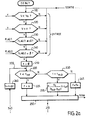
- an algorithm is shown indicating the succession of the steps of the driving assistance method according to a embodiment of the present invention for use in a situation tracking file.
- this algorithm is implemented by an assistance program stored in space brake controller memory 20 and executed in real time.
- the driver By switching the switch 90, the driver indicates that he wants to be helped to follow a line.
- the assistance program is then executed repetitively by the controller 20 so as to provide a driver assistance function.
- the assistance program tests the existence of a logical event input by testing if the instantaneous state of the vehicle checks a logical input condition.
- the logical input event is the intersection of input events respectively defined by the checking a basic input condition.
- the assistance program enters a main braking management loop, time-indexed loop.
- the vehicle is then slightly braked as long as the instantaneous state does not correspond to a logical output state, i.e., as long as an event output logic does not occur.
- the logical exit event is the meeting of exit events respectively defined by the audit an elementary exit condition. Only one of these basic exit conditions be checked for the program assistance stops braking the vehicle. We then leave the execution of the main loop to resume program execution at its beginning.
- the instantaneous state of the vehicle is compared to an entry state indicating that the vehicle needs to be braked.
- This state of entry is, in the presently envisaged embodiment, defined by the meeting of four basic entry requirements in addition to the that the switch 90 has been engaged by the driver
- the first input condition 110 is a condition on the speed. It is necessary that the speed V of the vehicle is lower than a threshold speed V 0 .
- the value of the threshold speed V 0 is low, for example 20 km / h. This means that if the speed of the vehicle is such that the speed is less than 20 km / h, the assistance function is likely to actuate the braking. For a speed greater than the threshold speed V 0 , it is estimated that the vehicle is not in a queue tracking situation and should not be slowed by the present function.
- the second input condition 120 is also a condition on the speed. To enter the main braking loop, the vehicle must not be stopped. We therefore ask that the velocity V is greater than zero. Indeed, it is not necessary to brake the vehicle if it is already at rest.
- the third input condition 130 is a condition on the Flagl clutch signal value.
- the clutch sensor 51 has been previously described as a sensor adapted to emit a signal having discrete values. To get into the main braking loop, he is required that the value of the clutch signal corresponds to the point of skating or complete disengagement. Indeed, if the driver shows off, this indicates that the vehicle is no longer driven by the engine. If no torque is applied, brake management can be taken over by the assistance function. As a result, the Flag1 signal from the clutch sensor must not be +1 corresponding to an engaged position of the pedal.
- the last input condition 140 is constituted by a condition on the accelerator pedal 40.
- the sensor 41 placed on the accelerator pedal 40 is a switch emitting a discrete signal.
- the fourth entry condition therefore corresponds to the verification that the Flag2 accelerator signal is zero, ie the driver do not press the accelerator pedal.
- the fact that the driver does not accelerate constitute information to say that the driver wishes to see the vehicle be braked.
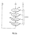
- the program enters into a 200 master brake management loop.
- the loop 200 is indexed by the value of a variable temporal t serving as a stopwatch.
- the variable t measures the duration flows from the input logical event, and is incremented periodically until an exit event occurs.
- the time variable t is initialized.
- the loop 200 starts with the comparison in step 220 of the value of the variable t with a predefined threshold lower threshold time t i , for example equal to 1.5 seconds. If the value of t is less than 1.5 seconds, the braking force F generated by the assistance program (step 225) is zero.
- the braking force generated is transmitted in step 250 as the target target braking force F to the actuating or regulating units 24 and 25 of the electromechanical brakes which equip the rear wheels. More precisely, the target target braking force F is emitted in the direction of an arbitration algorithm, moreover known. This algorithm selects from the set of target braking force requests sent to it from assistance functions but also for example from the ABS system, that of these requests which has the highest priority. This arbitration algorithm then transmits the selected target braking force to the remote control units.
- Step 230 consists in comparing the value of the time variable t to a threshold greater duration t sup predefined, for example 2.5 seconds. If the value of t is less than 2.5 seconds, then the generated braking force is an increasing function of t, i.e. time. For example, in step 235, the braking force F is an increasing linear function of time. The corresponding value of the target braking force is then transmitted towards the electromechanical brake control units (step 250).
- the value of the braking force F generated is equal to a saturation value of the braking force F 0 .
- the target braking force F 0 corresponds to a deceleration of the vehicle of 1.5 ms -2 . It should be noted that the maximum deceleration of the vehicle obtained by braking the two rear wheels only is of the order of 3 ms -2 .
- the corresponding value of the target braking force is transmitted towards the electromechanical brake control units.
- the execution of the time loop 200 continues with the checking a plurality of elementary output conditions which, when checked, respectively define events elementary output.
- the meeting of these elementary events defines a logical output event.
- the program immediately leaves the loop main 200 and resumes in step 110 the determination of the state instantaneous to enter the main braking loop, the switch 90 being always on the position in which the driver wishes to be attended.
- the first elementary output condition 310 is a condition on the speed V.
- the instantaneous speed V of the vehicle is compared to the null value. Indeed, if the vehicle is finally at stop, it is no longer necessary to continue the execution of the function assistance. If this condition on speed is not verified, the program proceeds to the verification of a second exit condition.
- the second elementary output condition 320 is a condition on the braking force F C requested by the driver by actuation of the brake pedal 6. If the braking force requested by the driver F C is greater than the current value of the force braking F generated by the assistance function, it is necessary to give the hand to the driver because it is probably an emergency braking. The assistance program must immediately leave the main brake management loop 200.
- This third output condition 330 relates to the state of the accelerator sensor 41. If the Flag2 signal from this sensor has a value equal to 1, it means that the driver depresses the accelerator pedal and wishes to restore speed to the vehicle. This means that the driver no longer wants the vehicle to idle. It is therefore necessary to leave the main brake control loop 200.
- the main loop 200 continues with the verification a fourth output condition 340 which relates to the value of the signal from the clutch sensor 51. If the signal value Flag 1 issued by the clutch sensor 51 is equal to +1, it means that the driver torque the engine to the wheels to drive the vehicle. It is necessary then leave the main loop 200 of the assistance function.
- step 220 the time variable t has been incremented, in real time, by a value predetermined ⁇ t, for example 10 milliseconds.
- step 220 allows a short period of time to elapse before a braking request is sent towards the rear electromechanical calipers. Indeed, it is possible that the entry conditions are verified a priori but that the driver does not wish, in fact, to see the vehicle be braked. During this time (1.5 seconds), the output conditions are regularly tested to give the opportunity to get out of the braking management loop. If the instantaneous state is such that the program remains in the main loop more than 1.5 seconds then the braking is progressively activated until the value of the target braking force reaches the saturation value F 0 .
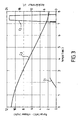
- Applicant has implemented the program described above in the brake controller 20 of a vehicle 1 having a hybrid braking system. Different tests have been carried out. Figure 3 shows the temporal variations of some variables during one of these tests.
- a braking force of zero value is required. Then, as the instantaneous state of the vehicle continues not to check one of the conditions of exit, the braking force is gradually increased so that the deceleration of the vehicle corresponds to a value of 1.5 ms -2 (curve C1) .
- the value of the braking force is kept constant at a maximum value, until an output event results in the output of the main braking management loop.
- the curve C2 represents the degree of depression of the accelerator pedal 40. Obviously, as soon as the driver presses on the accelerator pedal 40, the output condition 330 is verified. The program then stops issuing a target braking force request. It goes back to zero.
- Curve C3 represents the instantaneous speed of the vehicle during the test.
- the speed V decreases slightly and then more significantly and at a constant rate when the braking force required by the assistance function is equal to F 0 .
- the speed stops decreasing as quickly.
Landscapes
- Engineering & Computer Science (AREA)
- Transportation (AREA)
- Mechanical Engineering (AREA)
- Regulating Braking Force (AREA)
- Traffic Control Systems (AREA)
Abstract
Description
- déterminer un état instantané dudit véhicule défini par au moins une variable d'état dont la valeur est obtenue à partir de mesures effectuées au moyen d'au moins un capteur dont est équipé ledit véhicule ;
- tester un événement logique d'entrée en éprouvant si ledit état instantané vérifie une condition logique d'entrée; et, lorsque la condition logique d'entrée est vérifiée,
- tester un événement logique de sortie en éprouvant si ledit état instantané vérifie une condition logique de sortie ; et,
- générer et émettre une valeur de force de freinage en tant que force de freinage cible pour actionner lesdits étriers de frein, tant que ladite condition logique de sortie n'est pas vérifiée.
- un moyen de détermination d'un état instantané dudit véhicule, état défini par au moins une variable d'état obtenue à partir de mesures effectuées au moyen dudit au moins un capteur ;
- un moyen de test d'un événement logique d'entrée apte à éprouver si ledit état instantané vérifie une condition logique d'entrée ;
- un moyen de test d'un événement logique de sortie apte à éprouver si ledit état instantané vérifie une condition logique de sortie ;
- un moyen de génération et d'émission en sortie d'une valeur de force de freinage en tant que force de freinage cible ; et,
- un moyen d'incrémentation temps réel d'une variable temporelle.
- la figure 1 représente schématiquement un véhicule équipé d'un système de freinage hybride ;
- la figure 2 est un algorithme représentant les différentes étapes du procédé d'assistance à la conduite selon l'invention, mis en oeuvre sous forme logicielle dans le véhicule de la figure 1 ; et,
- la figure 3 montre des graphes donnant respectivement l'évolution temporelle de la force de freinage appliquée, de la vitesse du véhicule et de la sortie du capteur d'accélérateur.
Claims (18)
- Procédé d'assistance au freinage d'un véhicule, ledit véhicule (1) étant équipé d'un système de freinage comportant des étriers de frein aptes à être actionnés en fonction d'une force de freinage cible, ledit procédé étant caractérisé en ce qu'il comporte les étapes consistant à :déterminer un état instantané dudit véhicule défini par au moins une variable d'état dont la valeur est obtenue à partir de mesures effectuées au moyen d'au moins un capteur dont est équipé ledit véhicule ;tester un événement logique d'entrée en éprouvant si ledit état instantané vérifie une condition logique d'entrée (110-140); et, lorsque la condition logique d'entrée est vérifiée,tester un événement logique de sortie en éprouvant si ledit état instantané vérifie une condition logique de sortie (310-340) ; et,générer et émettre (225, 235, 245) une valeur de force de freinage (F) en tant que force de freinage cible (Fcible) pour actionner lesdits étriers de frein, tant que ladite condition logique de sortie n'est pas vérifiée.
- Procédé selon la revendication 1, caractérisé en ce que ledit événement logique d'entrée est défini par l'intersection d'une pluralité d'évènements d'entrée respectivement définis par la vérification d'une condition d'entrée élémentaire.
- Procédé selon la revendication 2, caractérisé en ce qu'une condition d'entrée élémentaire est une condition de vitesse maximale du véhicule (110), condition d'entrée qui est vérifiée lorsque la valeur instantanée de la vitesse du véhicule (V) est inférieure à une valeur seuil (V0).
- Procédé selon la revendication 2 ou la revendication 3, caractérisé en ce qu'une condition d'entrée élémentaire est une condition de vitesse minimale du véhicule (120), condition d'entrée qui est vérifiée lorsque la valeur instantanée de la vitesse du véhicule (V) est supérieure à une vitesse nulle.
- Procédé selon l'une des revendications 2 à 4, caractérisé en ce qu'une condition d'entrée élémentaire est une condition de position de pédale d'embrayage (130), condition d'entrée qui est vérifiée lorsque la valeur (Flag1) émise par un capteur (51) apte à détecter la position d'une pédale d'embrayage (50) correspond à une position complètement enfoncée de ladite pédale d'embrayage.
- Procédé selon l'une des revendications 2 à 5, caractérisé en ce qu'une condition d'entrée élémentaire est une condition de position de pédale d'accélérateur (140), condition d'entrée qui est vérifiée lorsque la valeur (Flag2) émise par un capteur (41) apte à détecter la position d'une pédale d'accélérateur (40), correspond à une position complètement relâchée de ladite pédale d'accélérateur.
- Procédé selon l'une des revendications 1 à 6, caractérisé en ce que ledit événement logique de sortie est défini par la réunion d'une pluralité d'évènements de sortie respectivement définis par la vérification d'une condition de sortie élémentaire.
- Procédé selon la revendication 7, caractérisé en ce qu'une condition de sortie élémentaire est une condition de vitesse du véhicule (310), condition de sortie qui est vérifiée lorsque la valeur instantanée de la vitesse (V) dudit véhicule est nulle.
- Procédé selon la revendication 7 ou la revendication 8, caractérisé en ce qu'une condition de sortie élémentaire est une condition de force de freinage (320), condition de sortie qui est vérifiée lorsque la valeur de la force de freinage demandée par le conducteur (FC) est supérieure à la valeur de la force de freinage (F) générée à l'étape de génération.
- Procédé selon l'une des revendications 7 à 9, caractérisé en ce qu'une condition de sortie élémentaire est une condition de position de pédale d'accélérateur (330), condition de sortie qui est vérifiée lorsque la valeur (Flag2) émise par un capteur (41) apte à détecter la position d'une pédale d'accélérateur (40), correspond à une position relâchée de ladite pédale d'accélérateur.
- Procédé selon l'une des revendications 7 à 10, caractérisé en ce qu'une condition de sortie élémentaire est une condition de position de pédale d'embrayage (340), condition qui est vérifiée lorsque la valeur (Flag1) émise par un capteur (51) apte à détecter la position d'une pédale d'embrayage (50) correspond à une position complètement enfoncée de ladite pédale d'embrayage.
- Procédé selon l'une des revendications 1 à 11, caractérisée en ce qu'il comporte une étape consistant à mesurer la durée depuis l'événement logique d'entrée, et en ce que ladite force de freinage générée a une valeur nulle tant que ladite durée est inférieure à une durée inférieure seuil (tinf) prédéfinie.
- Procédé selon l'une des revendications 1 à 12, caractérisée en ce qu'il comporte une étape consistant à mesurer la durée depuis l'événement logique d'entrée, et en ce que ladite force de freinage générée a une valeur qui est une fonction croissante de ladite durée.
- Logiciel d'assistance à la conduite contenant des instructions propres à être lues et stockées sur un support, lesdites instructions étant exécutables par un ordinateur hôte, caractérisé en ce que ledit logiciel met en oeuvre un procédé selon l'une quelconque des revendications 1 à 13.
- Contrôleur de freinage (20) programmable, apte à mettre en oeuvre un procédé selon l'une des revendications 1 à 13 dans un système de freinage d'un véhicule, comportant un espace mémoire apte à stocker des instructions d'un programme, un calculateur apte à exécuter lesdites instructions et une interface d'entrée/sortie connectable en entrée à au moins un capteur dont est équipé ledit véhicule, et en sortie à au moins une unité d'actionnement d'étrier de frein dudit système de freinage, caractérisé en ce que ledit contrôleur est programmé pour comporter :un moyen de détermination d'un état instantané dudit véhicule, état défini par au moins une variable d'état obtenue à partir de mesures effectuées au moyen dudit au moins un capteur ;un moyen de test d'un événement logique d'entrée apte à éprouver si ledit état instantané vérifie une condition logique d'entrée (110-140) ;un moyen de test d'un événement logique de sortie apte à éprouver si ledit état instantané vérifie une condition logique de sortie (310-340) ;un moyen de génération et d'émission en sortie (225, 235, 245) d'une valeur de force de freinage (F) en tant que force de freinage cible (Fcible) ; et,un moyen d'incrémentation temps réel d'une variable temporelle.
- Système de freinage destiné à équiper un véhicule comportant une pluralité de capteurs, un contrôleur de freinage, et des unités d'actionnement d'étriers de frein, caractérisé en ce que ledit contrôleur de freinage est un contrôleur de freinage programmable selon la revendication 15.
- Système de freinage selon la revendication 16, caractérisé en ce qu'il comporte au moins des étriers de frein électromécaniques destinées à équiper des roues arrière dudit véhicule.
- Véhicule comportant un système de freinage caractérisé en ce que ledit système de freinage est un système de freinage selon la revendication 16 ou la revendication 17.
Priority Applications (5)
| Application Number | Priority Date | Filing Date | Title |
|---|---|---|---|
| AT04291183T ATE495069T1 (de) | 2004-05-07 | 2004-05-07 | Funktion zur fahrunterstützung während des verfolgens einer reihe von fahrzeugen |
| EP04291183A EP1593567B1 (fr) | 2004-05-07 | 2004-05-07 | Fonction d'assistance à la conduite lors du suivi d'une file de véhicules |
| DE602004030995T DE602004030995D1 (de) | 2004-05-07 | 2004-05-07 | Funktion zur Fahrunterstützung während des Verfolgens einer Reihe von Fahrzeugen |
| JP2005127208A JP2005319990A (ja) | 2004-05-07 | 2005-04-25 | 車両の列に後続時の運転補助機能 |
| US11/120,367 US7917273B2 (en) | 2004-05-07 | 2005-05-03 | Driving assistance function on following a queue of vehicles |
Applications Claiming Priority (1)
| Application Number | Priority Date | Filing Date | Title |
|---|---|---|---|
| EP04291183A EP1593567B1 (fr) | 2004-05-07 | 2004-05-07 | Fonction d'assistance à la conduite lors du suivi d'une file de véhicules |
Publications (2)
| Publication Number | Publication Date |
|---|---|
| EP1593567A1 true EP1593567A1 (fr) | 2005-11-09 |
| EP1593567B1 EP1593567B1 (fr) | 2011-01-12 |
Family
ID=34931083
Family Applications (1)
| Application Number | Title | Priority Date | Filing Date |
|---|---|---|---|
| EP04291183A Expired - Lifetime EP1593567B1 (fr) | 2004-05-07 | 2004-05-07 | Fonction d'assistance à la conduite lors du suivi d'une file de véhicules |
Country Status (5)
| Country | Link |
|---|---|
| US (1) | US7917273B2 (fr) |
| EP (1) | EP1593567B1 (fr) |
| JP (1) | JP2005319990A (fr) |
| AT (1) | ATE495069T1 (fr) |
| DE (1) | DE602004030995D1 (fr) |
Families Citing this family (5)
| Publication number | Priority date | Publication date | Assignee | Title |
|---|---|---|---|---|
| US8565969B2 (en) | 2007-04-03 | 2013-10-22 | Clean Emissions Technologies, Inc. | Over the road/traction/cabin comfort retrofit |
| US9758146B2 (en) | 2008-04-01 | 2017-09-12 | Clean Emissions Technologies, Inc. | Dual mode clutch pedal for vehicle |
| DE112009002381T5 (de) * | 2008-09-26 | 2012-01-19 | Toyota Jidosha Kabushiki Kaisha | Automatisches Fahrzeugbremssystem und -verfahren |
| US9631528B2 (en) * | 2009-09-03 | 2017-04-25 | Clean Emissions Technologies, Inc. | Vehicle reduced emission deployment |
| US11712972B2 (en) | 2020-09-28 | 2023-08-01 | Ford Global Technologies, Llc | Electrified vehicle one pedal drive transition control |
Citations (4)
| Publication number | Priority date | Publication date | Assignee | Title |
|---|---|---|---|---|
| US4629043A (en) * | 1983-01-31 | 1986-12-16 | Mazda Motor Corporation | Electric parking brake system for a vehicle |
| EP1083075A1 (fr) * | 1999-09-09 | 2001-03-14 | Jaguar Cars Limited | Système de régulation de vitesse adaptatif avec commande de freinage |
| US20030227215A1 (en) * | 2000-12-18 | 2003-12-11 | Ralf Kinder | Method and device for controlling the braking equipment of a motor vehicle |
| US6679810B1 (en) * | 1998-10-14 | 2004-01-20 | Luk Lamellen Und Kupplungsbau Beteiligungs Kg | Hill holder device for a motor vehicle |
Family Cites Families (12)
| Publication number | Priority date | Publication date | Assignee | Title |
|---|---|---|---|---|
| JPH04201770A (ja) * | 1990-11-30 | 1992-07-22 | Isuzu Motors Ltd | 制動力保持装置 |
| JPH09295562A (ja) * | 1996-05-07 | 1997-11-18 | Mitsubishi Motors Corp | 坂道発進補助装置 |
| JP3927265B2 (ja) * | 1996-11-18 | 2007-06-06 | トヨタ自動車株式会社 | 車両の自動制動制御装置 |
| JP2000335387A (ja) * | 1999-05-25 | 2000-12-05 | Bosch Braking Systems Co Ltd | 車両のブレーキシステム |
| JP3580184B2 (ja) * | 1999-06-30 | 2004-10-20 | 日産自動車株式会社 | 車両用追従制御装置 |
| JP3546401B2 (ja) * | 1999-08-06 | 2004-07-28 | 本田技研工業株式会社 | 車両の駆動力制御装置 |
| US6670810B2 (en) * | 2000-04-25 | 2003-12-30 | Airak, Inc. | System and method for distributed monitoring of surroundings using telemetry of data from remote sensors |
| US6530450B2 (en) * | 2000-08-09 | 2003-03-11 | Deluca Michael | Fault reactive securely stopped vehicle method and apparatus |
| JP2002274347A (ja) * | 2001-01-09 | 2002-09-25 | Nissan Motor Co Ltd | 制動制御装置 |
| JP2003104184A (ja) * | 2001-09-27 | 2003-04-09 | Aisin Seiki Co Ltd | 車両用走行制御装置 |
| JP2004017889A (ja) * | 2002-06-19 | 2004-01-22 | Advics:Kk | 自動ブレーキ装置 |
| JP2004050925A (ja) * | 2002-07-18 | 2004-02-19 | Advics:Kk | 駐車補助ブレーキ装置 |
-
2004
- 2004-05-07 AT AT04291183T patent/ATE495069T1/de not_active IP Right Cessation
- 2004-05-07 DE DE602004030995T patent/DE602004030995D1/de not_active Expired - Lifetime
- 2004-05-07 EP EP04291183A patent/EP1593567B1/fr not_active Expired - Lifetime
-
2005
- 2005-04-25 JP JP2005127208A patent/JP2005319990A/ja active Pending
- 2005-05-03 US US11/120,367 patent/US7917273B2/en active Active
Patent Citations (4)
| Publication number | Priority date | Publication date | Assignee | Title |
|---|---|---|---|---|
| US4629043A (en) * | 1983-01-31 | 1986-12-16 | Mazda Motor Corporation | Electric parking brake system for a vehicle |
| US6679810B1 (en) * | 1998-10-14 | 2004-01-20 | Luk Lamellen Und Kupplungsbau Beteiligungs Kg | Hill holder device for a motor vehicle |
| EP1083075A1 (fr) * | 1999-09-09 | 2001-03-14 | Jaguar Cars Limited | Système de régulation de vitesse adaptatif avec commande de freinage |
| US20030227215A1 (en) * | 2000-12-18 | 2003-12-11 | Ralf Kinder | Method and device for controlling the braking equipment of a motor vehicle |
Also Published As
| Publication number | Publication date |
|---|---|
| US7917273B2 (en) | 2011-03-29 |
| EP1593567B1 (fr) | 2011-01-12 |
| ATE495069T1 (de) | 2011-01-15 |
| JP2005319990A (ja) | 2005-11-17 |
| DE602004030995D1 (de) | 2011-02-24 |
| US20060111828A1 (en) | 2006-05-25 |
Similar Documents
| Publication | Publication Date | Title |
|---|---|---|
| EP2137043B1 (fr) | Procede d'assistance aux manoeuvres en cote pour un vehicule | |
| EP1593566A1 (fr) | Fonction d'assistance à la conduite pour un véhicule immobilisé sur une pente | |
| EP2162336B1 (fr) | Procede d'assistance aux manoeuvres en cote | |
| EP2176950B1 (fr) | Procede d'assistance pour un vehicule | |
| EP3145783A1 (fr) | Procédé de contrôle d'un groupe motopropulseur d'un véhicule, dispositif et véhicule correspondant | |
| EP1584530A1 (fr) | Procédé d'assitance à la conduite en descente et dispositif associé | |
| EP2675651A2 (fr) | Systeme et procede de freinage d'un vehicule a traction electrique ou hybride | |
| EP1593567B1 (fr) | Fonction d'assistance à la conduite lors du suivi d'une file de véhicules | |
| EP1659042B1 (fr) | Procédé et système d'assistance à la conduite d'un véhicule | |
| FR2858032A1 (fr) | Procede et un dispositif d'assistance au demarrage d'un vehicule automobile arrete sur une surface en pente | |
| EP1621431A1 (fr) | Procédé et dispositif de répartition avant/arrière du freinage pour un véhicule en décélération | |
| EP1621432B1 (fr) | Procédé et dispositif de gestion du freinage intérieur/extérieur pour un véhicule en décélération en virage | |
| FR2949218A1 (fr) | Procede et dispositif de distribution d'un couple moteur entre un train avant et un train arriere de vehicule automobile muni de quatre roues motrices. | |
| EP1791743B1 (fr) | Procede d'elaboration d'une consigne de commande adaptee a une situation de freinage pour un dispositif de transmission d'un groupe motopropulseur de vehicule automobile et dispositif correspondant | |
| FR2857925A1 (fr) | Procede d'estimation de la pente d'une surface sur laquelle se trouve un vehicule automobile | |
| EP1791715B1 (fr) | Procede de commande a plusieurs modes de fonctionnement d'une transmission automatisee pour un vehicule automobile, notamment pour un avancement au ralenti du vehicule automobile avec frein active et dispositif correspondant | |
| FR2794833A1 (fr) | Procede de mise en oeuvre d'un changement de vitesse et changement de vitesse | |
| EP2555938B1 (fr) | Procede de commande du fonctionnement d'un moyen de couplage mecanique des premier et deuxieme essieux d'un vehicule automobile, procede de fonctionnement d'un systeme de transmission respectif, systemes correspondants, programme realisant les etapes des procedes, support d'enregistrement de donnees avec un tel programme et vehicule automobile avec un systeme respectif | |
| FR2806977A1 (fr) | Groupe motopropulseur de vehicule automobile comportant des moyens de maintien en pente | |
| EP1590216B1 (fr) | Procede de gestion de l'etat et du fonctionnement d'un vehicule automobile et systeme pour la mise en oeuvre de ce procede | |
| FR2936984A1 (fr) | Systeme de regulation automatique de la motricite d'un vehicule automobile pendant une phase de glissement des roues motrices du vehicule et suite a une saturation du couple moteur par le conducteur | |
| FR3053938A1 (fr) | Procede de pilotage d'un vehicule automobile roulant en marche arriere | |
| FR3147766A1 (fr) | Systeme de commande d'un dispositif de freinage apte a mettre en œuvre une fonction de freinage d'immobilisation | |
| FR2861023A1 (fr) | Installation de detection de la demande de poussee globale d'un conducteur de vehicule | |
| FR2937935A1 (fr) | Systeme de freinage de vehicule automobile, comportant une fonction d'aide au demarrage en cote. |
Legal Events
| Date | Code | Title | Description |
|---|---|---|---|
| PUAI | Public reference made under article 153(3) epc to a published international application that has entered the european phase |
Free format text: ORIGINAL CODE: 0009012 |
|
| 17P | Request for examination filed |
Effective date: 20050201 |
|
| AK | Designated contracting states |
Kind code of ref document: A1 Designated state(s): AT BE BG CH CY CZ DE DK EE ES FI FR GB GR HU IE IT LI LU MC NL PL PT RO SE SI SK TR |
|
| AX | Request for extension of the european patent |
Extension state: AL HR LT LV MK |
|
| AKX | Designation fees paid |
Designated state(s): AT BE BG CH CY CZ DE DK EE ES FI FR GB GR HU IE IT LI LU MC NL PL PT RO SE SI SK TR |
|
| 17Q | First examination report despatched |
Effective date: 20100226 |
|
| GRAP | Despatch of communication of intention to grant a patent |
Free format text: ORIGINAL CODE: EPIDOSNIGR1 |
|
| GRAS | Grant fee paid |
Free format text: ORIGINAL CODE: EPIDOSNIGR3 |
|
| GRAA | (expected) grant |
Free format text: ORIGINAL CODE: 0009210 |
|
| AK | Designated contracting states |
Kind code of ref document: B1 Designated state(s): AT BE BG CH CY CZ DE DK EE ES FI FR GB GR HU IE IT LI LU MC NL PL PT RO SE SI SK TR |
|
| REG | Reference to a national code |
Ref country code: GB Ref legal event code: FG4D Free format text: NOT ENGLISH |
|
| REG | Reference to a national code |
Ref country code: CH Ref legal event code: EP |
|
| REG | Reference to a national code |
Ref country code: IE Ref legal event code: FG4D Free format text: LANGUAGE OF EP DOCUMENT: FRENCH |
|
| REF | Corresponds to: |
Ref document number: 602004030995 Country of ref document: DE Date of ref document: 20110224 Kind code of ref document: P |
|
| REG | Reference to a national code |
Ref country code: DE Ref legal event code: R096 Ref document number: 602004030995 Country of ref document: DE Effective date: 20110224 |
|
| REG | Reference to a national code |
Ref country code: NL Ref legal event code: VDEP Effective date: 20110112 |
|
| PG25 | Lapsed in a contracting state [announced via postgrant information from national office to epo] |
Ref country code: GR Free format text: LAPSE BECAUSE OF FAILURE TO SUBMIT A TRANSLATION OF THE DESCRIPTION OR TO PAY THE FEE WITHIN THE PRESCRIBED TIME-LIMIT Effective date: 20110413 Ref country code: SE Free format text: LAPSE BECAUSE OF FAILURE TO SUBMIT A TRANSLATION OF THE DESCRIPTION OR TO PAY THE FEE WITHIN THE PRESCRIBED TIME-LIMIT Effective date: 20110112 Ref country code: ES Free format text: LAPSE BECAUSE OF FAILURE TO SUBMIT A TRANSLATION OF THE DESCRIPTION OR TO PAY THE FEE WITHIN THE PRESCRIBED TIME-LIMIT Effective date: 20110423 Ref country code: PT Free format text: LAPSE BECAUSE OF FAILURE TO SUBMIT A TRANSLATION OF THE DESCRIPTION OR TO PAY THE FEE WITHIN THE PRESCRIBED TIME-LIMIT Effective date: 20110512 |
|
| REG | Reference to a national code |
Ref country code: IE Ref legal event code: FD4D |
|
| PG25 | Lapsed in a contracting state [announced via postgrant information from national office to epo] |
Ref country code: AT Free format text: LAPSE BECAUSE OF FAILURE TO SUBMIT A TRANSLATION OF THE DESCRIPTION OR TO PAY THE FEE WITHIN THE PRESCRIBED TIME-LIMIT Effective date: 20110112 Ref country code: CY Free format text: LAPSE BECAUSE OF FAILURE TO SUBMIT A TRANSLATION OF THE DESCRIPTION OR TO PAY THE FEE WITHIN THE PRESCRIBED TIME-LIMIT Effective date: 20110112 Ref country code: SI Free format text: LAPSE BECAUSE OF FAILURE TO SUBMIT A TRANSLATION OF THE DESCRIPTION OR TO PAY THE FEE WITHIN THE PRESCRIBED TIME-LIMIT Effective date: 20110112 Ref country code: PL Free format text: LAPSE BECAUSE OF FAILURE TO SUBMIT A TRANSLATION OF THE DESCRIPTION OR TO PAY THE FEE WITHIN THE PRESCRIBED TIME-LIMIT Effective date: 20110112 Ref country code: BG Free format text: LAPSE BECAUSE OF FAILURE TO SUBMIT A TRANSLATION OF THE DESCRIPTION OR TO PAY THE FEE WITHIN THE PRESCRIBED TIME-LIMIT Effective date: 20110412 Ref country code: FI Free format text: LAPSE BECAUSE OF FAILURE TO SUBMIT A TRANSLATION OF THE DESCRIPTION OR TO PAY THE FEE WITHIN THE PRESCRIBED TIME-LIMIT Effective date: 20110112 Ref country code: NL Free format text: LAPSE BECAUSE OF FAILURE TO SUBMIT A TRANSLATION OF THE DESCRIPTION OR TO PAY THE FEE WITHIN THE PRESCRIBED TIME-LIMIT Effective date: 20110112 |
|
| PG25 | Lapsed in a contracting state [announced via postgrant information from national office to epo] |
Ref country code: DK Free format text: LAPSE BECAUSE OF FAILURE TO SUBMIT A TRANSLATION OF THE DESCRIPTION OR TO PAY THE FEE WITHIN THE PRESCRIBED TIME-LIMIT Effective date: 20110112 Ref country code: EE Free format text: LAPSE BECAUSE OF FAILURE TO SUBMIT A TRANSLATION OF THE DESCRIPTION OR TO PAY THE FEE WITHIN THE PRESCRIBED TIME-LIMIT Effective date: 20110112 Ref country code: IE Free format text: LAPSE BECAUSE OF FAILURE TO SUBMIT A TRANSLATION OF THE DESCRIPTION OR TO PAY THE FEE WITHIN THE PRESCRIBED TIME-LIMIT Effective date: 20110112 |
|
| PLBE | No opposition filed within time limit |
Free format text: ORIGINAL CODE: 0009261 |
|
| STAA | Information on the status of an ep patent application or granted ep patent |
Free format text: STATUS: NO OPPOSITION FILED WITHIN TIME LIMIT |
|
| BERE | Be: lapsed |
Owner name: PEUGEOT CITROEN AUTOMOBILES SA Effective date: 20110531 Owner name: DELPHI TECHNOLOGIES, INC. Effective date: 20110531 |
|
| PG25 | Lapsed in a contracting state [announced via postgrant information from national office to epo] |
Ref country code: SK Free format text: LAPSE BECAUSE OF FAILURE TO SUBMIT A TRANSLATION OF THE DESCRIPTION OR TO PAY THE FEE WITHIN THE PRESCRIBED TIME-LIMIT Effective date: 20110112 Ref country code: CZ Free format text: LAPSE BECAUSE OF FAILURE TO SUBMIT A TRANSLATION OF THE DESCRIPTION OR TO PAY THE FEE WITHIN THE PRESCRIBED TIME-LIMIT Effective date: 20110112 Ref country code: RO Free format text: LAPSE BECAUSE OF FAILURE TO SUBMIT A TRANSLATION OF THE DESCRIPTION OR TO PAY THE FEE WITHIN THE PRESCRIBED TIME-LIMIT Effective date: 20110112 |
|
| 26N | No opposition filed |
Effective date: 20111013 |
|
| PG25 | Lapsed in a contracting state [announced via postgrant information from national office to epo] |
Ref country code: IT Free format text: LAPSE BECAUSE OF FAILURE TO SUBMIT A TRANSLATION OF THE DESCRIPTION OR TO PAY THE FEE WITHIN THE PRESCRIBED TIME-LIMIT Effective date: 20110112 Ref country code: MC Free format text: LAPSE BECAUSE OF NON-PAYMENT OF DUE FEES Effective date: 20110531 |
|
| REG | Reference to a national code |
Ref country code: CH Ref legal event code: PL |
|
| GBPC | Gb: european patent ceased through non-payment of renewal fee |
Effective date: 20110507 |
|
| PG25 | Lapsed in a contracting state [announced via postgrant information from national office to epo] |
Ref country code: LI Free format text: LAPSE BECAUSE OF NON-PAYMENT OF DUE FEES Effective date: 20110531 Ref country code: CH Free format text: LAPSE BECAUSE OF NON-PAYMENT OF DUE FEES Effective date: 20110531 |
|
| REG | Reference to a national code |
Ref country code: DE Ref legal event code: R097 Ref document number: 602004030995 Country of ref document: DE Effective date: 20111013 |
|
| PG25 | Lapsed in a contracting state [announced via postgrant information from national office to epo] |
Ref country code: BE Free format text: LAPSE BECAUSE OF NON-PAYMENT OF DUE FEES Effective date: 20110531 |
|
| PG25 | Lapsed in a contracting state [announced via postgrant information from national office to epo] |
Ref country code: GB Free format text: LAPSE BECAUSE OF NON-PAYMENT OF DUE FEES Effective date: 20110507 |
|
| PGFP | Annual fee paid to national office [announced via postgrant information from national office to epo] |
Ref country code: FR Payment date: 20120608 Year of fee payment: 9 |
|
| PG25 | Lapsed in a contracting state [announced via postgrant information from national office to epo] |
Ref country code: LU Free format text: LAPSE BECAUSE OF NON-PAYMENT OF DUE FEES Effective date: 20110507 |
|
| PG25 | Lapsed in a contracting state [announced via postgrant information from national office to epo] |
Ref country code: TR Free format text: LAPSE BECAUSE OF FAILURE TO SUBMIT A TRANSLATION OF THE DESCRIPTION OR TO PAY THE FEE WITHIN THE PRESCRIBED TIME-LIMIT Effective date: 20110112 |
|
| PG25 | Lapsed in a contracting state [announced via postgrant information from national office to epo] |
Ref country code: HU Free format text: LAPSE BECAUSE OF FAILURE TO SUBMIT A TRANSLATION OF THE DESCRIPTION OR TO PAY THE FEE WITHIN THE PRESCRIBED TIME-LIMIT Effective date: 20110112 |
|
| REG | Reference to a national code |
Ref country code: FR Ref legal event code: ST Effective date: 20140131 |
|
| PG25 | Lapsed in a contracting state [announced via postgrant information from national office to epo] |
Ref country code: FR Free format text: LAPSE BECAUSE OF NON-PAYMENT OF DUE FEES Effective date: 20130531 |
|
| PGFP | Annual fee paid to national office [announced via postgrant information from national office to epo] |
Ref country code: DE Payment date: 20230321 Year of fee payment: 20 |
|
| REG | Reference to a national code |
Ref country code: DE Ref legal event code: R071 Ref document number: 602004030995 Country of ref document: DE |