EP1593537A1 - Volet à lamelles notamment pour ouvrant de véhicule automobile - Google Patents
Volet à lamelles notamment pour ouvrant de véhicule automobile Download PDFInfo
- Publication number
- EP1593537A1 EP1593537A1 EP05290949A EP05290949A EP1593537A1 EP 1593537 A1 EP1593537 A1 EP 1593537A1 EP 05290949 A EP05290949 A EP 05290949A EP 05290949 A EP05290949 A EP 05290949A EP 1593537 A1 EP1593537 A1 EP 1593537A1
- Authority
- EP
- European Patent Office
- Prior art keywords
- flap
- connecting rod
- axis
- opening
- shutter
- Prior art date
- Legal status (The legal status is an assumption and is not a legal conclusion. Google has not performed a legal analysis and makes no representation as to the accuracy of the status listed.)
- Withdrawn
Links
- 241000446313 Lamella Species 0.000 claims description 20
- 230000001154 acute effect Effects 0.000 claims description 3
- 230000006835 compression Effects 0.000 claims description 2
- 238000007906 compression Methods 0.000 claims description 2
- 238000007789 sealing Methods 0.000 description 3
- 101001017827 Mus musculus Leucine-rich repeat flightless-interacting protein 1 Proteins 0.000 description 2
- 230000008602 contraction Effects 0.000 description 1
- 230000010339 dilation Effects 0.000 description 1
- 230000000694 effects Effects 0.000 description 1
- 230000003472 neutralizing effect Effects 0.000 description 1
- 244000045947 parasite Species 0.000 description 1
- 230000000284 resting effect Effects 0.000 description 1
- 210000001364 upper extremity Anatomy 0.000 description 1
Images




Classifications
-
- B—PERFORMING OPERATIONS; TRANSPORTING
- B60—VEHICLES IN GENERAL
- B60J—WINDOWS, WINDSCREENS, NON-FIXED ROOFS, DOORS, OR SIMILAR DEVICES FOR VEHICLES; REMOVABLE EXTERNAL PROTECTIVE COVERINGS SPECIALLY ADAPTED FOR VEHICLES
- B60J5/00—Doors
- B60J5/10—Doors arranged at the vehicle rear
- B60J5/12—Doors arranged at the vehicle rear slidable; foldable
- B60J5/14—Doors arranged at the vehicle rear slidable; foldable of roller-blind type made of rigid elements
Definitions
- the present invention relates to a slider flap for closing an opening, for example an opening of a van of a utility vehicle.
- Some commercial vehicles have a van whose rear has an opening closed by a flap with sliding slats.
- flap shutters consist of a plurality of connected slats they are articulated and guided by rollers that run in rails lateral guides.
- Such flaps can be moved between a closed position and an open position.
- the closed position usually vertical
- the shutters are lowered and obstruct the opening they are intended to close.
- the flaps are raised and in a generally horizontal position under the flag of the van of the utility vehicle.
- the shutter To move from the vertical position to the position horizontally, the shutter must curve through a rounded area of guide rails. These rounded areas have the disadvantage of neutralizing part of the height under the flag and therefore part of the volume of useful volume of the van.
- This volume is neutralized, in particular because the last lamella of the shutter, that is to say the slat that is in the upper part when the flap is closed, can not be in position vertical, and thus ensure a good seal of the closure, that when completely out of the rounded portion of the guide rail.
- the object of the present invention is to remedy this drawback by proposing a slat shutter slidable between a position of closure and an opening position of an opening, presenting a small footprint when the flap is in the open position, while ensuring a good seal of the closure when the shutter is in closing position.
- the subject of the invention is a slat shutter which can slide between a closed position and an open position generally perpendicular to the closed position, of the type comprising a plurality of slats hinged together, guided in translation by rollers cooperating with at least one guide rail disposed on the edge of the shutter, and each having two substantially rectilinear portions connected by a curvilinear portion disposed at the junction of the open positions and closure, and further comprising means for subjecting a folding movement at the moment of opening or closing flap, the end strip located in the vicinity of the junction between the position opening and closing position when the shutter is closed.
- the means for subjecting the slide to a folding movement end is constituted for example by at least one rod articulated to a first end to the end strip, and comprising at a second end a laterally projecting head, oblong, cooperating with a curvilinear circulation track with the end in which the head is protruding side when the shutter is closed, is shaped to ensure a Partial locking in translation of the connecting rod and allow movement in rotation of the connecting rod.
- the longitudinal axis of the protruding head of oblong shape and the longitudinal axis of the connecting rod make an acute angle between them.
- the first end of the connecting rod is articulated around an axis extending laterally beyond the end strip and extending inside a guide rail of the flap rollers, and the track curvilinear circulation is shaped so that, in the open position, the axis around which the rod is articulated, cooperates with an edge of the guide rail.
- the connecting rod and the runway of the conrod head are shaped so that the axis around which the connecting rod is articulated, the projecting head of the connecting rod and the axis of rotation of the rollers of guiding the end lamella are not aligned.
- the distance from the projecting head of the connecting rod to the line joining the axis around which the connecting rod is articulated and the axis of rotation guide rollers of the end plate, is maximum when the shutter is in the vicinity of its closed position.
- the body of the connecting rod is preferably perpendicular at the end slat.
- the invention also relates to an opening of a motor vehicle equipped with a flap according to the invention.
- This flap is preferably such that in position of closing, for any temperature of the standard temperature range of use of a motor vehicle the end strip exerts on a joint sealing the opening a compression.
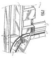
- the slat shutter partially shown in FIG. comprises, when in the closed position, at its upper part, a lamella end 1 which extends laterally across an opening 2 of a utility vehicle van (in the figure, only the end slat is represented, but the flap is constituted, in a known manner, a plurality of lamellae arranged in extension, downwards, of the end plate).
- the end strip 1 has in its part bottom of the guide rollers 3 (in the figure only one pebble is visible but the lamella has a roller on each side).
- the guide rollers 3 circulate in guide rails 4 arranged on either side of the lamella 1 and included in the lateral amounts 2 'of the opening 2.
- Each rail of 4 comprises on the one hand a substantially vertical rectilinear portion 5 which extends along the lateral edge of the opening 2, and on the other hand, a part rectilinear substantially horizontal 6 which extends under flag 10 of van.
- the rectilinear vertical parts 5 and horizontal 6 are connected by a curvilinear connecting portion 7 in the form of a circular arc.
- the upper end plate 1 also includes, at each of its upper extremities (only one is visible in the figure), a connecting rod 8 one end cooperates with a runway 12.
- the rod 8 allows, at the moment of opening the shutter, to make toggle the upper end plate 1 and thus, allows to extend opening 2 to the vicinity of pavilion 10, and on the other hand to ensure good sealing of the closure by a suitable pressure of the lamella end 1 against a seal disposed at the edge of the opening 2.
- the rod 8 is articulated to its first end 8A to the end plate 1 via an axis 16, and comprises, at a second end 8B, a lateral projecting head oblong 11 whose longitudinal axis YY forms an acute angle ⁇ with the axis longitudinal XX of the connecting rod.
- the laterally projecting head 11 cooperates with a curvilinear circulation track 12 disposed in the lateral amount of the vehicle, under the guide rail 4.
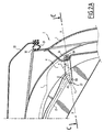
- This runway has been lower end 13 located in the vicinity of the junction point of the part curved 7 and the vertical rectilinear portion 5 of the guide rail, until under the horizontal straight portion 6 of the rail 4.
- the lower end 13 of the track 12, in which is located the oblong lateral projection head 11 when the flap is in the closed position, is wide enough to allow the oblong lateral projection head 11 to pivot, and has a notch 14 which locks in translation the elongated lateral projection head 11 of the connecting rod 8 when the connecting rod has not rotated sufficiently relative to its position normal closure in which the longitudinal axis XX of the connecting rod is perpendicular to the end plate 1.
- the end 18 of the end plate 1 bears against a joint 19 disposed on the periphery of the van opening and carried by the flag 10 of the van. This end 18 of the end plate 1 in contact with the seal 19 and crushing this seal, ensures a good seal at the closing of the opening by the lamella shutter.
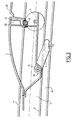
- the end plate 1 rests on the one hand via the end 8A of the connecting rod on one of the lower banks 17 of the generally horizontal rectilinear portion 6 of the guide rail 4, and on the other hand, through the roller 3 on the same edge 17 of the rail of guide.
- the oblong lateral projection head 11 of the connecting rod 8 which is inside the rectilinear running track 12 is in such a position that there is a clearance between this head 11 and the edges of the Curvilinear circulation track 12.
- the dimensions and the relative positions of the connecting rod 8, the slat end 1, of the roller 3, and the end 13 of the curvilinear running track 12, must be such that the hinge axis 16 of the connecting rod and the flap A, the axis of rotation A2 of the elongated lateral projection head 11 of the connecting rod cooperating with the end 13 of the curvilinear circulation track 12, and the axis of rotation A3 of the guide roller 3 of the end plate 1 are not never aligned, so that when translational force is exerted on the flap 1 from top to bottom or bottom to top, there's always a torque that ensures easy rotation of the connecting rod 8 when his head 11 arrives in the end 13 of the curvilinear circulation track 12.
- the seal 19 on which the end 18 of the lamella 1 comes to bear when the shutter is closed must be chosen to have a crash rate sufficient.
- the closing flap of an automotive utility vehicle may operate on a standard temperature range of use of the vehicle which ranges from -30 ° C to + 85 ° C.
- the temperature of use normal being conventionally fixed at 20 ° C.
- the flap expands very significantly, of the order of a few centimeters, and the expansions of the shutter have the effect of modifying the position of the connecting rod 8 and therefore the position of the end 18 of the lamella end 1.
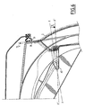
- the end 13 of the runway 12 must be shaped to allow the downward pivoting of the oblong lateral projection head 11 of the connecting rod 8.
- the dimensions of the seal 19 must be chosen so that, in the normal closed position, the crushing of the seal 19 by the end 18 of the flap 1 is sufficient to absorb the consequences of dilations or contractions resulting from temperature variations of the shutter.
- the slat end 1 is shaped along its lower edge to be able to cooperate with a slat 30 that is immediately behind and that is also articulated on the guide roller 3.
- the lamella end 1 comprises in this zone a seal 21 which can ensure the sealing of the two slats when the shutter is in the closed position in resting on the end 31 of the adjacent flap 30. It comprises also a stop 20 which allows the whole component to have a good mechanical behavior at the moment of opening, coming to bear on the end 31 of the adjacent flap 30. This support makes it possible to transmit the pushing forces from one lamella to another.
- the opening is in position vertical. It is opened by pushing the shutter upwards and closed by pulling the shutter down.
- the slat that must switch when the opening is the upper end plate. But the craftsman will understand easily that any other arrangement is possible.
- the slat that must pivot is the end slat shutter which, when the shutter is closed, is located in the transit zone of the closed position to the open position.
Landscapes
- Engineering & Computer Science (AREA)
- Mechanical Engineering (AREA)
- Vehicle Step Arrangements And Article Storage (AREA)
- Cooling, Air Intake And Gas Exhaust, And Fuel Tank Arrangements In Propulsion Units (AREA)
Abstract
Description
- la figure 1 est une vue en perspective partielle de la partie latérale haute d'un volet à lamelles en position de fermeture.
- les figures 2A, 2B et 2C, sont des vues en coupe latérale de la partie haute d'un volet à lamelles en position de fermeture et de deux positions intermédiaires d'ouverture.
- La figure 3 est une vue en coupe latérale de l'extrémité supérieure d'un volet à lamelles en position ouverte.
- La figure 4 est une vue de dessus, selon la coupe CC de la figure 2A, d'une lamelle d'extrémité d'un volet à lamelles.
- La figure 5 est une vue en coupe latérale de la lamelle supérieure d'un volet à lamelles en position de fermeture dans des conditions de température élevée.
- La figure 6 est une vue latérale en coupe d'une lamelle d'extrémité d'un volet à lamelles en position de fermeture, à une température basse.
Claims (10)
- Volet à lamelles pouvant coulisser entre une position de fermeture et une position d'ouverture généralement perpendiculaire à la position de fermeture, du type comprenant une pluralité de lamelles (1, 30) articulées entre elles, guidées en translation par des galets (3) coopérant avec au moins un rail de guidage (4), disposé en bordure du volet, et comportant deux parties sensiblement rectilignes (5, 6) raccordées par une partie curviligne (7) disposée à la jonction des positions d'ouverture et de fermeture, caractérisé en ce qu'il comprend, en outre, un moyen (8) pour soumettre à un mouvement de rabattement au moment de l'ouverture ou de la fermeture du volet, la lamelle d'extrémité (1) du volet située au voisinage de la jonction entre la position d'ouverture et la position de fermeture lorsque le volet est fermé.
- Volet à lamelles selon la revendication 1, caractérisé en ce que le moyen pour soumettre à un mouvement de rabattement la lamelle d'extrémité (1) est constitué d'au moins une bielle (8) articulée à une première extrémité (8A) à ladite lamelle d'extrémité (1), et comportant à une deuxième extrémité (8B) une tête en saillie latérale (11), de forme oblongue, coopérant avec une piste de circulation curviligne (12) dont l'extrémité (13) dans laquelle se trouve la tête en saillie latérale (11) lorsque le volet est fermé, est conformée pour assurer un blocage partiel en translation de la bielle (8) et permettre un mouvement en rotation de la bielle (8).
- Volet à lamelles selon la revendication 2, caractérisé en ce que l'axe longitudinal (YY) de la tête en saillie latérale (11) de forme oblongue et l'axe longitudinal (XX) de la bielle font entre eux un angle aigu.
- Volet à lamelles selon la revendication 2 ou la revendication 3, caractérisé en ce que la première extrémité (8A) de la bielle (8) est articulée autour d'un axe (16) se prolongeant latéralement au-delà de la lamelle d'extrémité (1) et s'étendant à l'intérieur d'un rail de guidage (4) des galet des volets.
- Volet à lamelles selon la revendication 4, caractérisé en ce que la piste de circulation curviligne (12) est conformée pour que, en position d'ouverture, l'axe (16) autour duquel la bielle (8) est articulée, coopère avec un bord du rail (17) de guidage (4).
- Volet à lamelles selon l'une quelconque des revendications 2 à 5, caractérisé en ce que la bielle (8) et la piste de circulation (12) de la tête de bielle sont conformées de telle sorte que l'axe (16) autour de laquelle la bielle (8) est articulée, l'axe de pivotement (A2) de la tête en saillie latérale (11) de la bielle (8) et l'axe de rotation (A3) des galets (3) de guidage de la lamelle d'extrémité (1) ne sont jamais alignés.
- Volets à lamelles selon la revendication 6, caractérisé en ce que la distance de la tête en saillie (11) de la bielle (8) à la ligne joignant l'axe (16) autour duquel la bielle est articulée et l'axe de rotation (A3) des galets de guidage (3) de la lamelle d'extrémité (1), est maximal lorsque le volet est au voisinage de sa position de fermeture.
- Volet à lamelles selon l'une quelconque des revendications 2 à 7, caractérisé en ce que dans les conditions de température normale d'utilisation, lorsque le volet est en position de fermeture, le corps de la bielle (8) est perpendiculaire à la lamelle d'extrémité (1).
- Ouvrant de véhicule automobile caractérisé en ce qu'il est muni d'un volet selon l'une quelconque des revendications 1 à 8.
- Ouvrant selon la revendication 9 caractérisé en ce qu'en position de fermeture, pour toute température de la plage de température standard d'utilisation du véhicule automobile la lamelle d'extrémité (1) exerce un effort de compression sur un joint d'étanchéité (19) de l'ouvrant.
Applications Claiming Priority (2)
| Application Number | Priority Date | Filing Date | Title |
|---|---|---|---|
| FR0404842A FR2869940B1 (fr) | 2004-05-05 | 2004-05-05 | Volet a lamelle notamment pour ouvrant de vehicule automobile |
| FR0404842 | 2004-05-05 |
Publications (1)
| Publication Number | Publication Date |
|---|---|
| EP1593537A1 true EP1593537A1 (fr) | 2005-11-09 |
Family
ID=34942233
Family Applications (1)
| Application Number | Title | Priority Date | Filing Date |
|---|---|---|---|
| EP05290949A Withdrawn EP1593537A1 (fr) | 2004-05-05 | 2005-04-29 | Volet à lamelles notamment pour ouvrant de véhicule automobile |
Country Status (2)
| Country | Link |
|---|---|
| EP (1) | EP1593537A1 (fr) |
| FR (1) | FR2869940B1 (fr) |
Citations (3)
| Publication number | Priority date | Publication date | Assignee | Title |
|---|---|---|---|---|
| CH549487A (de) * | 1971-03-10 | 1974-05-31 | Bachert Geb | Aufbau fuer kraftfahrzeuge, insbesondere loeschfahrzeuge. |
| US3848920A (en) * | 1972-10-03 | 1974-11-19 | J Linhart | Cargo deflector panel |
| DE19836432A1 (de) * | 1997-08-28 | 1999-03-04 | Gerard Grosse | Hubtürsystem |
-
2004
- 2004-05-05 FR FR0404842A patent/FR2869940B1/fr not_active Expired - Fee Related
-
2005
- 2005-04-29 EP EP05290949A patent/EP1593537A1/fr not_active Withdrawn
Patent Citations (3)
| Publication number | Priority date | Publication date | Assignee | Title |
|---|---|---|---|---|
| CH549487A (de) * | 1971-03-10 | 1974-05-31 | Bachert Geb | Aufbau fuer kraftfahrzeuge, insbesondere loeschfahrzeuge. |
| US3848920A (en) * | 1972-10-03 | 1974-11-19 | J Linhart | Cargo deflector panel |
| DE19836432A1 (de) * | 1997-08-28 | 1999-03-04 | Gerard Grosse | Hubtürsystem |
Also Published As
| Publication number | Publication date |
|---|---|
| FR2869940A1 (fr) | 2005-11-11 |
| FR2869940B1 (fr) | 2006-08-04 |
Similar Documents
| Publication | Publication Date | Title |
|---|---|---|
| EP0857844B1 (fr) | Dispositif de guidage pour un panneau coulissant et louvoyant d'obturation d'une baie | |
| BE1014506A3 (fr) | Dispositif a volet avec element de reintroduction. | |
| FR2539081A1 (fr) | Toit coulissant-levant pour vehicule | |
| FR2650027A1 (fr) | Systeme de guidage d'une porte a plusieurs vantaux coulissants | |
| FR2648403A1 (fr) | Mecanisme d'ouverture, de fermeture et d'entrebaillement d'un panneau mobile par rapport a une surface fixe, notamment pour toit ouvrant d'un vehicule automobile | |
| FR2971458A1 (fr) | Toit ouvrant pour vehicule automobile avec une position d'ouverture sous un pavillon | |
| EP0827869A1 (fr) | Enjoliveur de recouvrement pour gouttière de pavillon de véhicule | |
| FR2613986A1 (fr) | Porte a rideau relevant notamment pour vehicule de transport | |
| FR2657305A1 (fr) | Toit de vehicule ouvrant ou ouvrant et coulissant a pivotement variable de l'arriere vers l'avant du toit d'un vehicule. | |
| FR2983130A1 (fr) | Mecanisme de fermeture d'un toit ouvrant en toile | |
| EP1456500B1 (fr) | Dispositif a volet avec chemins de guidage | |
| FR2845037A1 (fr) | Toit ouvrant pour vehicule automobile | |
| FR2872751A1 (fr) | Dispositif de rangement pliable pour vehicule automobile, planche de bord de vehicule et vehicule ainsi equipes | |
| EP2687671B1 (fr) | Ensemble d'une porte coulissante et de son encadrement délimitant une ouverture pratiquée dans une construction | |
| EP3885524B1 (fr) | Dispositif de butée pour volet roulant | |
| EP0877141B1 (fr) | Joint automatique rétractable pour bas de porte | |
| FR3066442A1 (fr) | Dispositif d'encadrement de trou de caisse a etancheite amelioree | |
| FR2527157A1 (fr) | Caisson telescopique, en particulier pour camping-car | |
| FR2817804A1 (fr) | Mecanisme de fermeture de toit ouvrant en toile pour vehicule automobile | |
| EP1939383B1 (fr) | Système de fermeture d'espace de rangement à porte(s) coulissante(s) | |
| FR2797656A1 (fr) | Agencement d'une porte coulissante sur un vehicule | |
| FR2553347A1 (fr) | Porte d'acces pour vehicule de transport en commun | |
| WO2006027472A1 (fr) | Porte de vehicule equipee d'un joint | |
| FR2921869A1 (fr) | Toit avec couverture souple. | |
| EP1437248A1 (fr) | Dispositif de guidage d'un ouvrant coulissant, ouvrant et véhicule automobile pourvu d'un dispositif |
Legal Events
| Date | Code | Title | Description |
|---|---|---|---|
| PUAI | Public reference made under article 153(3) epc to a published international application that has entered the european phase |
Free format text: ORIGINAL CODE: 0009012 |
|
| AK | Designated contracting states |
Kind code of ref document: A1 Designated state(s): AT BE BG CH CY CZ DE DK EE ES FI FR GB GR HU IE IS IT LI LT LU MC NL PL PT RO SE SI SK TR |
|
| AX | Request for extension of the european patent |
Extension state: AL BA HR LV MK YU |
|
| 17P | Request for examination filed |
Effective date: 20060426 |
|
| AKX | Designation fees paid |
Designated state(s): AT BE BG CH CY CZ DE DK EE ES FI FR GB GR HU IE IS IT LI LT LU MC NL PL PT RO SE SI SK TR |
|
| GRAP | Despatch of communication of intention to grant a patent |
Free format text: ORIGINAL CODE: EPIDOSNIGR1 |
|
| STAA | Information on the status of an ep patent application or granted ep patent |
Free format text: STATUS: THE APPLICATION IS DEEMED TO BE WITHDRAWN |
|
| 18D | Application deemed to be withdrawn |
Effective date: 20090303 |