EP1592822B1 - Disk coating system - Google Patents
Disk coating system Download PDFInfo
- Publication number
- EP1592822B1 EP1592822B1 EP04703559A EP04703559A EP1592822B1 EP 1592822 B1 EP1592822 B1 EP 1592822B1 EP 04703559 A EP04703559 A EP 04703559A EP 04703559 A EP04703559 A EP 04703559A EP 1592822 B1 EP1592822 B1 EP 1592822B1
- Authority
- EP
- European Patent Office
- Prior art keywords
- processing
- substrate
- carrier
- station
- chamber
- Prior art date
- Legal status (The legal status is an assumption and is not a legal conclusion. Google has not performed a legal analysis and makes no representation as to the accuracy of the status listed.)
- Expired - Lifetime
Links
Images








Classifications
-
- C—CHEMISTRY; METALLURGY
- C23—COATING METALLIC MATERIAL; COATING MATERIAL WITH METALLIC MATERIAL; CHEMICAL SURFACE TREATMENT; DIFFUSION TREATMENT OF METALLIC MATERIAL; COATING BY VACUUM EVAPORATION, BY SPUTTERING, BY ION IMPLANTATION OR BY CHEMICAL VAPOUR DEPOSITION, IN GENERAL; INHIBITING CORROSION OF METALLIC MATERIAL OR INCRUSTATION IN GENERAL
- C23C—COATING METALLIC MATERIAL; COATING MATERIAL WITH METALLIC MATERIAL; SURFACE TREATMENT OF METALLIC MATERIAL BY DIFFUSION INTO THE SURFACE, BY CHEMICAL CONVERSION OR SUBSTITUTION; COATING BY VACUUM EVAPORATION, BY SPUTTERING, BY ION IMPLANTATION OR BY CHEMICAL VAPOUR DEPOSITION, IN GENERAL
- C23C16/00—Chemical coating by decomposition of gaseous compounds, without leaving reaction products of surface material in the coating, i.e. chemical vapour deposition [CVD] processes
- C23C16/44—Chemical coating by decomposition of gaseous compounds, without leaving reaction products of surface material in the coating, i.e. chemical vapour deposition [CVD] processes characterised by the method of coating
- C23C16/458—Chemical coating by decomposition of gaseous compounds, without leaving reaction products of surface material in the coating, i.e. chemical vapour deposition [CVD] processes characterised by the method of coating characterised by the method used for supporting substrates in the reaction chamber
- C23C16/4582—Rigid and flat substrates, e.g. plates or discs
- C23C16/4587—Rigid and flat substrates, e.g. plates or discs the substrate being supported substantially vertically
-
- C—CHEMISTRY; METALLURGY
- C23—COATING METALLIC MATERIAL; COATING MATERIAL WITH METALLIC MATERIAL; CHEMICAL SURFACE TREATMENT; DIFFUSION TREATMENT OF METALLIC MATERIAL; COATING BY VACUUM EVAPORATION, BY SPUTTERING, BY ION IMPLANTATION OR BY CHEMICAL VAPOUR DEPOSITION, IN GENERAL; INHIBITING CORROSION OF METALLIC MATERIAL OR INCRUSTATION IN GENERAL
- C23C—COATING METALLIC MATERIAL; COATING MATERIAL WITH METALLIC MATERIAL; SURFACE TREATMENT OF METALLIC MATERIAL BY DIFFUSION INTO THE SURFACE, BY CHEMICAL CONVERSION OR SUBSTITUTION; COATING BY VACUUM EVAPORATION, BY SPUTTERING, BY ION IMPLANTATION OR BY CHEMICAL VAPOUR DEPOSITION, IN GENERAL
- C23C14/00—Coating by vacuum evaporation, by sputtering or by ion implantation of the coating forming material
- C23C14/22—Coating by vacuum evaporation, by sputtering or by ion implantation of the coating forming material characterised by the process of coating
- C23C14/56—Apparatus specially adapted for continuous coating; Arrangements for maintaining the vacuum, e.g. vacuum locks
- C23C14/568—Transferring the substrates through a series of coating stations
-
- C—CHEMISTRY; METALLURGY
- C23—COATING METALLIC MATERIAL; COATING MATERIAL WITH METALLIC MATERIAL; CHEMICAL SURFACE TREATMENT; DIFFUSION TREATMENT OF METALLIC MATERIAL; COATING BY VACUUM EVAPORATION, BY SPUTTERING, BY ION IMPLANTATION OR BY CHEMICAL VAPOUR DEPOSITION, IN GENERAL; INHIBITING CORROSION OF METALLIC MATERIAL OR INCRUSTATION IN GENERAL
- C23C—COATING METALLIC MATERIAL; COATING MATERIAL WITH METALLIC MATERIAL; SURFACE TREATMENT OF METALLIC MATERIAL BY DIFFUSION INTO THE SURFACE, BY CHEMICAL CONVERSION OR SUBSTITUTION; COATING BY VACUUM EVAPORATION, BY SPUTTERING, BY ION IMPLANTATION OR BY CHEMICAL VAPOUR DEPOSITION, IN GENERAL
- C23C16/00—Chemical coating by decomposition of gaseous compounds, without leaving reaction products of surface material in the coating, i.e. chemical vapour deposition [CVD] processes
- C23C16/44—Chemical coating by decomposition of gaseous compounds, without leaving reaction products of surface material in the coating, i.e. chemical vapour deposition [CVD] processes characterised by the method of coating
- C23C16/54—Apparatus specially adapted for continuous coating
-
- G—PHYSICS
- G11—INFORMATION STORAGE
- G11B—INFORMATION STORAGE BASED ON RELATIVE MOVEMENT BETWEEN RECORD CARRIER AND TRANSDUCER
- G11B5/00—Recording by magnetisation or demagnetisation of a record carrier; Reproducing by magnetic means; Record carriers therefor
-
- G—PHYSICS
- G11—INFORMATION STORAGE
- G11B—INFORMATION STORAGE BASED ON RELATIVE MOVEMENT BETWEEN RECORD CARRIER AND TRANSDUCER
- G11B5/00—Recording by magnetisation or demagnetisation of a record carrier; Reproducing by magnetic means; Record carriers therefor
- G11B5/84—Processes or apparatus specially adapted for manufacturing record carriers
- G11B5/8404—Processes or apparatus specially adapted for manufacturing record carriers manufacturing base layers
-
- H—ELECTRICITY
- H10—SEMICONDUCTOR DEVICES; ELECTRIC SOLID-STATE DEVICES NOT OTHERWISE PROVIDED FOR
- H10P—GENERIC PROCESSES OR APPARATUS FOR THE MANUFACTURE OR TREATMENT OF DEVICES COVERED BY CLASS H10
- H10P72/00—Handling or holding of wafers, substrates or devices during manufacture or treatment thereof
- H10P72/04—Apparatus for manufacture or treatment
- H10P72/0451—Apparatus for manufacturing or treating in a plurality of work-stations
- H10P72/0452—Apparatus for manufacturing or treating in a plurality of work-stations characterised by the layout of the process chambers
-
- H—ELECTRICITY
- H10—SEMICONDUCTOR DEVICES; ELECTRIC SOLID-STATE DEVICES NOT OTHERWISE PROVIDED FOR
- H10P—GENERIC PROCESSES OR APPARATUS FOR THE MANUFACTURE OR TREATMENT OF DEVICES COVERED BY CLASS H10
- H10P72/00—Handling or holding of wafers, substrates or devices during manufacture or treatment thereof
- H10P72/04—Apparatus for manufacture or treatment
- H10P72/0451—Apparatus for manufacturing or treating in a plurality of work-stations
- H10P72/0452—Apparatus for manufacturing or treating in a plurality of work-stations characterised by the layout of the process chambers
- H10P72/0458—Apparatus for manufacturing or treating in a plurality of work-stations characterised by the layout of the process chambers vertical arrangement
-
- H—ELECTRICITY
- H10—SEMICONDUCTOR DEVICES; ELECTRIC SOLID-STATE DEVICES NOT OTHERWISE PROVIDED FOR
- H10P—GENERIC PROCESSES OR APPARATUS FOR THE MANUFACTURE OR TREATMENT OF DEVICES COVERED BY CLASS H10
- H10P72/00—Handling or holding of wafers, substrates or devices during manufacture or treatment thereof
- H10P72/04—Apparatus for manufacture or treatment
- H10P72/0451—Apparatus for manufacturing or treating in a plurality of work-stations
- H10P72/0462—Apparatus for manufacturing or treating in a plurality of work-stations characterised by the construction of the processing chambers, e.g. modular processing chambers
-
- H—ELECTRICITY
- H10—SEMICONDUCTOR DEVICES; ELECTRIC SOLID-STATE DEVICES NOT OTHERWISE PROVIDED FOR
- H10P—GENERIC PROCESSES OR APPARATUS FOR THE MANUFACTURE OR TREATMENT OF DEVICES COVERED BY CLASS H10
- H10P72/00—Handling or holding of wafers, substrates or devices during manufacture or treatment thereof
- H10P72/04—Apparatus for manufacture or treatment
- H10P72/0451—Apparatus for manufacturing or treating in a plurality of work-stations
- H10P72/0464—Apparatus for manufacturing or treating in a plurality of work-stations characterised by the construction of the transfer chamber
-
- H—ELECTRICITY
- H10—SEMICONDUCTOR DEVICES; ELECTRIC SOLID-STATE DEVICES NOT OTHERWISE PROVIDED FOR
- H10P—GENERIC PROCESSES OR APPARATUS FOR THE MANUFACTURE OR TREATMENT OF DEVICES COVERED BY CLASS H10
- H10P72/00—Handling or holding of wafers, substrates or devices during manufacture or treatment thereof
- H10P72/04—Apparatus for manufacture or treatment
- H10P72/0451—Apparatus for manufacturing or treating in a plurality of work-stations
- H10P72/0468—Apparatus for manufacturing or treating in a plurality of work-stations comprising a chamber adapted to a particular process
-
- H—ELECTRICITY
- H10—SEMICONDUCTOR DEVICES; ELECTRIC SOLID-STATE DEVICES NOT OTHERWISE PROVIDED FOR
- H10P—GENERIC PROCESSES OR APPARATUS FOR THE MANUFACTURE OR TREATMENT OF DEVICES COVERED BY CLASS H10
- H10P72/00—Handling or holding of wafers, substrates or devices during manufacture or treatment thereof
- H10P72/04—Apparatus for manufacture or treatment
- H10P72/0478—Apparatus for manufacture or treatment the substrates being processed being not semiconductor wafers, e.g. leadframes or chips
-
- H—ELECTRICITY
- H10—SEMICONDUCTOR DEVICES; ELECTRIC SOLID-STATE DEVICES NOT OTHERWISE PROVIDED FOR
- H10P—GENERIC PROCESSES OR APPARATUS FOR THE MANUFACTURE OR TREATMENT OF DEVICES COVERED BY CLASS H10
- H10P72/00—Handling or holding of wafers, substrates or devices during manufacture or treatment thereof
- H10P72/06—Apparatus for monitoring, sorting, marking, testing or measuring
- H10P72/0612—Production flow monitoring, e.g. for increasing throughput
Definitions
- This invention relates to a system and processes for handling and processing thin substrates such as substrates used in making magnetic disks. More particularly, the invention relates to an improved system for processing substrates, including simultaneously on both sides, in several processing stations and using various coating techniques.
- U.S. Patents 5,215,420 and 5,425,611 describe equipment that is primarily used to manufacture disks today. This equipment is available from Intevac, Inc. of Santa Clara, CA and is marketed as the MPD 250. The equipment includes a main chamber, entrance and output load locks, substrate load and unload stages and a plurality of processing stations. Disks are fed into the system transported and treated in processing stations and then are fed from the system as disks ready for use as hard disks in computer applications. Prior to the development of the MPD 250, there existed equipment in this field as described in U.S. Patent 4,981,408 which equipment was at one time available from Varian Associates of Palo Alto, CA. Another manufacturer in this field is Anelva Corporation of Fuchu, Japan.
- Anelva manufactures a unit designated the C-3040.
- One of its objectives is to deposit films of greater thickness on the substrate.
- Patents describing this system are U.S. Patents 6,027,618 , 6,228,439 B1 and 6,251,232 B1 . These background patents are all incorporated into this disclosure by reference.
- a linear machine has the same type of problems experienced with a radial system. It has a large footprint and to change the substrate holder, requires that the system and production be stopped. Any add-on, if possible, extends the footprint and eventually the number of stations would be controlled by space constraints of the facility.
- US 5 658 114 shows a modular vaccum system with two interconnected, parallel transport paths which may be arranged either above or next to one another.
- the present invention provides a rabstrati processing system according to claim 1.
- the preferred embodiment of the present invention is a system that processes substrates in a vertical position on both sides simultaneously with high throughput in a structure with a comparatively small footprint.
- the system has flexibility and permits the addition of process stations.
- the system can be segmented so that substrate carriers can be limited to certain process stations and then changed so that clean carriers are used in other stations. This has not been a capability of prior art units and this characteristic allows coating substrates using processes which would normally deposit onto the carrier and then contaminate subsequent processing stations.
- the system can be a stand alone type system or may be connected to another system to extend the capabilities of the other system.
- the system architecture enable both static processing in which the substrate is stationary during processing and pass by processing in which the substrate moves during processing.
- the architecture of this invention also permits adding additional stations without substantially changing the footprint as to enable additional processes to be performed on a substrate as technology requirements change to enable increasing the throughput of the unit.
- Another modification permits replacing the substrate holder with one that holds more than one substrate in each of the process stations as to double or increase even more the output, again without impacting the footprint of the unit.
- the present invention further provides a processing chamber according to claim 19 and a method according to claim 20.
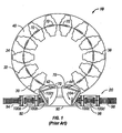
- FIG. 1 A prior art substrate processing system is shown in Figure 1 where like elements have the same reference numerals.
- the system includes a processing unit 10 and a substrate handling system 20.
- the processing unit 10 includes a plurality of process stations 30, 32, 34, etc. mounted on a main vacuum chamber 40. Process stations 30, 32, 34, etc. are mounted in a circular arrangement with respect to a circular central main vacuum chamber 40.
- Processing unit 10 further includes a loading station 42 for loading substrates into the system for processing and an unloading station 44 for unloading substrates from the system following processing.
- the substrates are typically substrates for making magnetic hard disks or for making magnetic optical disks.
- the substrates and ultimate disks include a central opening.
- the substrate processing system may further include vacuum pumps, power supplies and a controller (not shown).
- Processing is carried out in the different process stations 30, 32, 34, etc., which may be the same or different, depending on the requirements of the system.
- the system has twelve process stations, loading station 42 and unloading station 44, which are equiangularly spaced.
- the process stations may comprise a one or more heating stations, sputter stations, cooling stations, chemical vapor deposition stations and the like, as are employed in the art in manufacturing magnetic disks.
- the substrates are moved through the system as to serially transfer to and be processed by the process stations, one after another and for the same amount of time at each station.
- the substrate holder also seals the process station from the main vacuum chamber during processing operations as to avoid contamination within the process stations and the central chamber.
- the substrate handling system 20 includes a buffer vacuum chamber 90, a load lock 92, an entrance conveyor 94, an unload lock 96 and an exit conveyor 98.
- Cassettes 100a, 100b, 100c and 100d carrying substrates for processing enter buffer vacuum chamber 90 through load lock 92 and exit from buffer vacuum chamber 90 through unload lock 96.
- a load arm 102 in this configuration, transfers substrates from cassette 100b to disk gripper or lifter 70 in loading station 42.
- An unload arm 104 transfers substrates from disk gripper or disk lifter 70 in unloading station 44 to cassette 100c.
- Substrate handling system 20 is described in detail in the aforementioned Patent No. 5,215,420, which is hereby incorporated by reference.
- FIG 2 there is shown a preferred embodiment of a system in accordance with this invention.
- This comprises a number of process stations in a stacked relationship, with a second layer of process stations positioned on top of a base layer of process stations.
- It is a system without the large central vacuum main chamber that is found in the prior art system illustrated in Figure 1 . It permits controlled cycling for substrates being processed travelling through the system. It considerably reduces the footprint occupied by systems in the prior art and enables more process stations. It therefore permits a greater number of process operations on substrates passing through the system or in a much smaller footprint the same number of operations as may have been performed in a prior art unit with a significantly larger footprint.
- each process station is separately pumped by an attached vacuum pump such as a turbo-molecular or cryo-pump as to create an independent atmosphere for processes performed at each station as will be illustrated and discussed in connection with subsequent figures.
- an attached vacuum pump such as a turbo-molecular or cryo-pump
- FIG. 2 a 23 station processing system is illustrated. In fact the number of stations could be more or less than this number.
- the stations are identified as 101-123.
- a cassette of substrates is fed into the load/unload aperture 126.
- the cassette travels along a path into position at load/unload station 129.
- a disk carrier (see Figure 4A ) moves into the load/unload chamber 129 where a transfer mechanism, on the unload side, grips a disk in the disk carrier that had been through the processing cycle, by its inner hole.
- the jaws of the disk carrier are then opened and the processed substrate is removed from the disk carrier and transferred to a lift blade similar to the one described as prior art in connection with Figure 1 .
- the lift blade then places the substrate or disk into a cassette.
- a lift blade again like the one used in the prior art, lifts a substrate or disk from the cassette and raises it into the load chamber.
- a transfer mechanism transfers the disk from the lift blade and transfers it to the disk carrier where jaws 134 and 139 close to grip the disk in the disk carrier (see Figure 4A ).
- the disk carrier then moves to an elevator 128 and is lifted (as illustrated) to a level adjacent to the upper set of process stations and directly adjacent to station 101.
- the substrate and carrier then move as a unit and transfer into station 101 where processing of the disk is started. Thereafter, the combined unit of a substrate 130 and a disk carrier, move into the adjacent processing station 102.
- the substrate and disk carrier move on to the adjacent station 103 where the disk is carried through additional processing operations.
- the substrate on the disk carrier travel from one processing chamber to the next along the upper level in series from 101 to 112 where the combined unit enters elevator 131.
- the combined unit is then lowered to the lower lever along which it travels from station 123 back to station 113.
- the elevator chamber may include a cold trap, such as a water pump or a Meisner trap to remove moisture from the disk and the vacuum system.
- the disk may be heated to continue its preconditioning prior to being carried through coating processing.
- Power controls 132 are positioned as shown above and below the processing stations. They may however, be located at the ends of the system. In the instance where the system requires a large number of controls for power intensive processes, the controls may be positioned in separate cabinets.
- the system is programmed and driven by entries at an operator station 133 at the left side of system 125 as shown in Figure 2 but shown more clearly in Figure 6A .
- station 127 is described as a load/unload station, it may in fact act only to load substrates into the system with the unload operation performed at the other end, for example, adjacent to station 123.
- An unload station would be found on the backside of the unit shown in Figure 2 in a position opposite the load station on the facing side. This will be shown more clearly in a subsequent figure.
- a disk carrier with a disk or substrate in place moves into the unload chamber.
- a transfer mechanism takes the disk from jaws 134 and 139 (see Figure 4 ) which open and release the disk to the transfer mechanism.
- the transfer mechanism may be a system as is used on the structure of Figure 1 or as subsequently discussed. This mechanism transfers the disk to the unload blade (which may conform to the load blade as used at the load station and also to the load blade used in connection with Figure 1 ), where the disk is lowered into the load side of a cassette.
- Figure 2 illustrates a system 125 with 23 stations.
- a full system of 23 or more stations may not be required or the substrates, in such a case, can be directed and controlled to move only through a limited group of active process stations or less than all the process stations can be operational.
- a smaller system can be used.
- Such a system could for example include less process stations.
- a benefit to such a structure is that it enables the existing manufacturers to tie their existing units to the system of this invention as to enable additional or new processes to be performed in making magnetic disks in a limited additional area or footprint. This will be further discussed in connection with Figure 6 below.
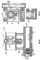
- Figure 3 is shown a single process module 135 and in Figure 4A , a disk carrier 136 is illustrated with a substrate 130 in place.
- Figure 4B there is shown the mechanism to transfer disks into the carrier at the load station and to transfer disks out of the disk carrier at the unload station.
- Figure 4C there is shown another view of the mechanism in Figure 4B with more detail in connection with the disk carrier and the arrangement of the disk on the carrier.
- Disk carrier 136 is shown in position in Figure 3 in process module 135.
- Isolation valve 144 and isolation valve driver 145 operate to close and open opening 129 of the chamber 135.
- the substrate 130 is positioned into the disk carrier and held in place in the disk carrier throughout its travels. It is released following processing in the various processing chambers by a transfer mechanism that grips the disk by its inner hole and a gripper actuator and a gripper actuator mechanism that opens the carrier jaws after the disk is gripped for unloading or before the disk is ungripped for loading. These manipulations are illustrated in Figure 4B and 4C .
- FIG 4B a cassette 202 of substrates has been fed into transfer section 201 through the load door 204. At this point the substrates are in the vacuum environment. The substrates will remain in a vacuum environment for all manipulations from this point on until the processed substrates leave the transfer station 201 by being unloaded at the unload zone 207 back into a cassette and removed from the transfer station and the equipment in a cassette holder through the unload door 208.
- a cassette of disks 202 is shown in position at the load section of this subsystem.
- the cassette holder rides on wheels 206 that transport the cassette holder into position to place substrates into position to be lifted out of cassette holder 202, upwardly through transfer zone 203 and to disk loading zone 205 where the substrates are loaded into the disk carrier.
- the disk is lifted out of the cassette by a disk lifter similar to the lifter used in the prior art system illustrated in Figure 1 .
- the lifter travels up through opening 222 and then through the cassette where it engages a substrate and then lifts the substrate through transfer zone 203 and into disk loading zone 205.
- a similar lifter is employed to transfer coated substrates back to the cassette 224 receiving substrate which when fully loaded exits transfer station 201.
- the lifter takes a substrate from the unload zone and moves down through the path on the unload side and then through the cassette where the substrate remains as the lifter arm moves on through opening 223.
- a pick-up arm 210 moves outwardly and into the hole in the middle of the substrate.
- This arm 210 connects to the substrate by clips that are inserted into the center section of the substrate and there grasp the inner edges of the substrate center hole or opening.
- the arm 210 then moves back to the position shown in this Figure where it actuates a mechanism 211 which in turn opens the jaws of a disk carrier.
- the disk carrier jaws are then positioned around the disk or substrate, remove the disk from the pick-up arm, and grasp the disk to carry it through the various processes of the equipment
- Figure 4C is a side view of this disk load/ unload section shown In Figure 4B in this Figure a disk carrier 136 is shown in side view.
- wheels 137 located in the transport drive section 212 are in view.
- the wheels are used to transport the disk carrier throughout the systems.
- Disk carriers are moved from process chamber to process chamber by a magnetic drive system 212 in part, located at the base of each chamber and in part, as a mating structure located on the base of each disk carrier 216.
- Each disk carrier and each chamber have independent transport elements for operation with the magnetic drive system 212.
- the wheels for this system are driven by an ordinary motor utilizing a rotary vacuum feed through but they may be replaced by a linear motor.
- the disk carriers are moved by way of a soft magnetic material, such as 400 series stainless steel mounted in the carrier base 216. Illustrated in the lower section of Figure 4C is the side view of the cassette 202 in the lower chamber.
- magnet actuating systems 211 that are energized to open the disk carrier 136 as to permit the insertion of a substrate 130 or to release a processed substrate in the unload zone 207.
- Four such magnets are shown. However fewer or more may be used to accomplish the purpose of opening and closing the jaws of the substrate holder.
- This structure is attached to the disk carrier 136 and permits the processing of substrates of different diameters.
- the halo structure can be widened or narrowed or even removed from the disk carrier as to permit the positioning of varying sized substrates in the holder for processing.
- the disk or substrate in position in the disk carrier is held at its edges by the halo structure 213 or if none is in use then by the disk carrier 136 itself.
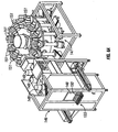
- Figures 5A shows the structure of a typical process chamber 135 in which processing operations are performed in system 125.
- the disk holder positions disks in the upper opening.
- the sides 140 when fully assembled include isolation seals to isolate the chamber from adjacent chambers and the rest of the system.
- a cold trap, vacuum pump or instrumentation may be placed at the top opening 142.
- the primary vacuum pump for a chamber is positioned adjacent to the chamber on the isolation valve body (shown in Figure 5B ) and pumping is through opening 140.
- each chamber has its own cryo, turbo or other suitable pump to maintain uniform and controlled vacuum environments in each of the chambers.
- the front opening as well as the back opening are used for example in connection with a chamber doing sputter deposition, to position sources with targets on each side of the substrate being coated or processed.
- Other processing devices may also be positioned at these openings as to become chamber walls enclosing the processing chamber.
- the wheels and lower section of the disk carrier At the openings at the base there are positioned the wheels and lower section of the disk carrier, a seal to close off openings and drive motors 163 for the transport.
- Figure 5B illustrates a processing station showing elements in place.
- the turbo pump 149 with 2 sputtering sources 143 mounted on the chamber frame 135.
- isolation valve 144 which seals this chamber on its right side.
- On the left side an opening 129is shown to fit this chamber against other chambers or to an elevator.
- An adjacent chamber would normally have an isolation valve on the side fitted to this chamber so that the chambers are isolated from each other.
- FIG. 6A there is illustrated a stacked system 146 connected to a circular system 147.
- This combined unit may comprise a complete processing system or may illustrate the addition of more process capabilities to existing circular units by providing stacked process stations feeding to or from systems like those presently in use commercially in the art and illustrated in Figure 1 .
- the circular portion 147 with process stations 151, is supported by rails 144, processes substrates sequentially by moving the substrates from chamber 151 to a next chamber.
- the first section of this unit 146 illustrates process stations in a line. These can be identified by the vacuum pumps 149 attached at the upper portion of the process chambers.
- this section 146 may include a lower layer of process stations beneath those appearing connected to vacuum pumps 149. This is shown in Figure 6B .
- a vacuum pump exists for each process chamber. Similar vacuum pumps extend below the process chambers for process chambers at the lower portion of the stack at 146. Again this is seen in Figure 6B .
- a screen 148 and keyboard 150 comprise operator station 133 to control operation of the equipment.
- the circular configuration 147 includes single processing chambers with vacuum pumps attached.
- the substrate in the disk carrier of section 146 will transfer disks into the substrate handling system of Figure 1 or to disk gripper 70 at loading station 42 to thereafter be fed into and through the system.
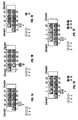
- Figure 7 A-E is a set of diagrams illustrating how disks may be moved through the stacked system illustrated for example in Figure 2 .
- Figure 7 comprises five different diagrams. Illustrated is how the arrangement of disks as they enter a process chamber and then how the disks are transferred between stations. The disks are numbered 1-5, and 18-25 for purposes of following movement from place to place in the diagrams.
- disk 1 is in position in the lower or entry section of elevator 128 and disk 2 is at the entry station.
- Substrates 3, 4 and 5 are awaiting entry into the equipment and would normally be positioned in a cassette awaiting transfer into the disk carrier.
- Figure 7B the elevator moves disk 1 to the top level into a position to enter into the processing chambers for processing and disk 18 exits and is separated from its disk carrier as is described in connection with Figures 4 A-C . It is then loaded into an unload cassette. Disk 2 in this Figure is being loaded into a disk carrier in the load station again in accordance with the discussion in connection with Figures 4 A-C .
- disk 1 is moved in a disk carrier into a first process station while disk 2 mounted into a disk carrier moves into the elevator and 18, a completed coated substrate is moved out of the system.
- Disk 3 is positioned for entry into the system and disk 19 is being readied to exit and is being separated from its disk carrier. The other disks shown in Figure 7C are shown moved through the system.
- disks 25, 24 and 23 each move one station to the right (compared to positions occupied in Figure 7B ) and disk 1 moves into a processing station.
- the disk at the final position of the top layer at the right moves downwardly so that disk 22 now occupies the last position on the right of the lower layer while the other disks on the lower layer move one station each to the left.
- a new disk 4 is getting ready to enter the system while disk 20 is about to exit the system.
- disk 23 ( Figure 7C ) moves down to the station below ( Figure 7D ).
- disk 5 is shown entering the system, disk 4 mounted in a disk carrier is on the elevator and ready to move up to the entry station now occupied by disk 3.
- the disks move over and down following the route illustrated in the previous figures and disk 20 moves out of the system.
- all the original disks 3, 4 and 5 that were awaiting entry into the system in Figure 7A have entered and 3 new substrates 6, 7, and 8 are shown awaiting entry.
- disks 18, 19 and 20 have been completed and have been removed from the system.
- the system includes an elevator on both the left and right sides. On the left side the elevator moves disks to the top level of chambers for processing and on the right side the elevator lowers the disks for processing in the lower level and the disks return to the entry point along the lower process levels and then exit the system.
- FIGs 8A-E the equipment is shown in two parts with a swing arm to move substrates from one part to the other. Again the substrates have been numbered to simplify following their paths and travel.
- substrates 6, 7 and 8 are in position waiting to enter the system.
- Substrates 10 and 11 have been processed and have been moved out of the equipment.
- Substrate 12 joins the completed substrates in Figure 8B and substrate 25 is moved by swing arm 153 from a group of stacked processing stations at the left to another at the right.
- substrates 6, 7 and 8 are in the system and are being processed while 12 and 13 have exited the system and joined the completed disks where they would be repositioned into the cassette holder. Also disks have moved from station to station as shown in Figures 8A-E .
- a carrier exchange module 156 Carriers present during processing of substrates at various process stations become coated with materials being deposited at the process stations.
- a substrate of aluminum may be initially coated using sputtering techniques with a chromium layer followed by the deposition of a cobalt alloy followed thereafter by the deposition of other layers as determined by the user in accordance with its process of manufacture, frequently proprietary, to manufacture magnetic disks.
- a final area of deposition may be based on creating a diamond like coating using, for example, a plasma enhanced chemical vapor deposition to deposit carbon, as for example is disclosed and discussed in U.S.6,368,678 B1 .
- the system of this invention includes stations strategically positioned to permit the carrier to be changed to a fresh and clean carrier before further processing of the substrate takes place.
- Figure 9 illustrates such an exchange module
- Figure 10 A-D illustrates a carrier exchange sequence.
- a clean carrier 155 is loaded into the exchange module 156.
- the clean carrier may be loaded into this module by hand or alternatively by automatically feeding new carriers as programmed into the system to occur after a set number of uses of a carrier in process stations or a set number of exposures of carriers to particular process steps and/or depositions.
- a clean carrier in the carrier exchange module is first preconditioned so that impurities have been removed before they have had a deleterious effect on subsequent operations and on the coated substrate itself.
- the carrier exchange module may be placed at the end of the in-line structure, at either end or at both ends or in an equivalent position. For example it could be beyond the elevators as illustrated in Figure 8A where the stations are identified as 156 and 159.
- a like station can also be placed at the point of the swing arm shown in Figures 8 A-E ,
- This structure permits the changing of disk carriers as the disk is moved from a first section to a second section of the process chambers so that when the disk enters the second section it can enter with a pre-cleaned disk carrier to effectively insulate the disk from the processes in the first section of the unit.
- a disk carrier may be transferred out of service by entering the module for cleaning following the transfer of a disk from the disk carrier.
- a vacuum pump 149 and an isolation valve 144 there is illustrated a vacuum pump 149 and an isolation valve 144.
- Such a structure can be positioned as shown in Figure 8A at 156 or 159 or may also be positioned to replace disk carriers at the point of the swing arm or at any other point where contamination will follow if the carrier is not changed.
- the system shown in Figure 6A if connecting to existing equipment, requires a hand off of the disk apart from the disk carrier when the disk moves from the in line equipment 146 where it travels in a disk carrier to the circular version 147 where the disk may be lifted from the disk carrier or from a cassette into which the disk is placed on entry into the circular portion 147 of the system.
- a station 156 such as is shown in Figure 9 can be provided at this point to separate the disk from the carrier as the disk completes its travels through section 146 and enters 147.
- the disk can be reinstalled into a clean disk carrier at a station like that in Figure 9 .
- a carrier exchange module is shown in a position beyond elevator 128.
- the system in Figure 10 is programmed to skip load a carrier when the new carrier is ready.
- the new carrier 155 is used to replace the skip loaded carrier 157. This is illustrated by the empty carrier 157 in the initial chamber.
- the empty carrier follows a normal sequence of travelling upward in elevator 128. This is shown in Figure 10B .
- 10C there is illustrated the exchange of carriers.
- the clean carrier 155 replaces the carrier being exchanged 157 and as shown in Figure 10D the clean carrier moves into the normal flow cycle and the new carrier requiring cleaning 157 is cleaned and then is inserted into the exchange module to be used to replace the next carrier requiring renewal.
- FIG. 11 there is illustrated a disk carrier which holds two disks at the same time. This is achieved using a gripping mechanism 161 that holds two disks in position for processing in the various process chambers as the disk carrier moves through the system. This design can double the throughput of the system since the same time will be consumed in each process chamber whether there are two or one disk in the disk carrier.
- Figure 12 illustrates a cycle that is useable with the system 125 illustrated in Figure 2 .
- This cycle is based on 5.1 seconds per operation. One second is used for transport and 4.1 seconds are used for processing. These times can obviously be varied but system 125 is operable in accordance with these time constraints. Operating at these speeds results in the production of 700 coated substrates per hour and operating a normal eight hour day produces in excess of a million and a half disks per month.
- a disk carrier may enter a process station and be continuously moved through a number of process stations during processing. This is known as pass by processing. This has an advantage for certain types of depositions. It is also possible to tie two or more processing stations together and process substrates for more time in the same processes. Thus instead, for example, of using 2 or more process stations to bring a substrate to temperature, two or more process stations can be combined into a single larger process station as to perform the desired function in a single station or the equivalent of a single station that normally requires considerable movement and multiple stations for the same results.
- the processing time usually used for a cycle is about 5 seconds
- this can be either a very short period and too short a time for certain process operations or a long period for some process operations and thus the equipment can be programmed for varying operations.
- This can be dealt with in the equipment of this invention by combining process stations into a larger station as to allow the disk carrier to dwell longer in a station and permit processes that may require two or three time the amount of time required for other operations or it may be achieved by slowing down the cycle provided those operations requiring less time are properly adjusted.
Landscapes
- Chemical & Material Sciences (AREA)
- Engineering & Computer Science (AREA)
- Chemical Kinetics & Catalysis (AREA)
- Materials Engineering (AREA)
- Mechanical Engineering (AREA)
- Metallurgy (AREA)
- Organic Chemistry (AREA)
- General Chemical & Material Sciences (AREA)
- Manufacturing & Machinery (AREA)
- Manufacturing Of Magnetic Record Carriers (AREA)
- Physical Vapour Deposition (AREA)
Description
- This invention relates to a system and processes for handling and processing thin substrates such as substrates used in making magnetic disks. More particularly, the invention relates to an improved system for processing substrates, including simultaneously on both sides, in several processing stations and using various coating techniques.
- As was described by a disk manufacturer in the N.Y. Times, July 1, 2002, "The plastic tray they sell you to carry your drive home is a higher gross margin product " than the modern computer hard disk. Yet we demand that the disk include as much technology in today's world as a complex computer chip. This invention is directed to improving manufacture of such disks to permit the creation of higher technology on the disks and to help bring cost down.
-
U.S. Patents 5,215,420 and5,425,611 describe equipment that is primarily used to manufacture disks today. This equipment is available from Intevac, Inc. of Santa Clara, CA and is marketed as the MPD 250. The equipment includes a main chamber, entrance and output load locks, substrate load and unload stages and a plurality of processing stations. Disks are fed into the system transported and treated in processing stations and then are fed from the system as disks ready for use as hard disks in computer applications. Prior to the development of the MPD 250, there existed equipment in this field as described inU.S. Patent 4,981,408 which equipment was at one time available from Varian Associates of Palo Alto, CA. Another manufacturer in this field is Anelva Corporation of Fuchu, Japan. Anelva manufactures a unit designated the C-3040. One of its objectives is to deposit films of greater thickness on the substrate. Patents describing this system areU.S. Patents 6,027,618 ,6,228,439 B1 and6,251,232 B1 . These background patents are all incorporated into this disclosure by reference. - One fault with these prior art systems is that they occupy a rather large footprint. Some are excessively long. Others cover a generally rectangular area and this generally is an entire room. Since these units for the manufacture of disks are typically operated in clean rooms oversized units compel excessively sized and extremely expensive clean rooms.
- Recently it has also become recognized that as the art has progressed it has become necessary to supplement the original systems with add-ons. For example, one such add-on is a lube station to lubricate disks before they are removed from the tool. This is described in
U.S. Patent 6,183,831 B1 and in the parent application Serial No.09/562,039, filed May 1, 2000 U.S. Patents 6,101,972 ,6,203,862 and6,368,678 B1 . - In radial systems there is a limit as to how many processing stations can function as part of the unit. Typically, existing systems are limited to about 12 stations. Adding additional stations requires considerable redesign of the equipment and the factory facilities with the expectation that a system with more stations would increase its footprint considerably. In these systems the same substrate holder is generally used to carry the substrate to and through the various stations of the unit. If it becomes necessary or desirable to change the substrate holder this would require stopping operation of the system and its production of output. Also it has not been possible to do processing in these systems while the substrate is moving and this prevents the deposition of very thin layers which can be deposited when deposition is carried out in a pass by mode:
- A linear machine has the same type of problems experienced with a radial system. It has a large footprint and to change the substrate holder, requires that the system and production be stopped. Any add-on, if possible, extends the footprint and eventually the number of stations would be controlled by space constraints of the facility.
US 5 658 114 shows a modular vaccum system with two interconnected, parallel transport paths which may be arranged either above or next to one another. - The present invention provides a rabstrati processing system according to
claim 1. - The preferred embodiment of the present invention is a system that processes substrates in a vertical position on both sides simultaneously with high throughput in a structure with a comparatively small footprint. The system has flexibility and permits the addition of process stations. The system can be segmented so that substrate carriers can be limited to certain process stations and then changed so that clean carriers are used in other stations. This has not been a capability of prior art units and this characteristic allows coating substrates using processes which would normally deposit onto the carrier and then contaminate subsequent processing stations. The system can be a stand alone type system or may be connected to another system to extend the capabilities of the other system. The system architecture enable both static processing in which the substrate is stationary during processing and pass by processing in which the substrate moves during processing. The architecture of this invention also permits adding additional stations without substantially changing the footprint as to enable additional processes to be performed on a substrate as technology requirements change to enable increasing the throughput of the unit. Another modification permits replacing the substrate holder with one that holds more than one substrate in each of the process stations as to double or increase even more the output, again without impacting the footprint of the unit. These and other benefits and improvements will be discussed in the descriptions that follow.
- The present invention further provides a processing chamber according to
claim 19 and a method according toclaim 20. - For a better understanding of the present invention, reference is made to the accompanying drawings, which are incorporated herein by reference and in which:
-
Figure 1 is a top view of a prior art substrate processing system; -
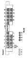
Figure 2 is a schematic view of an illustrative 23 station system in accordance with this invention; -
Figure 3 is a schematic view of a single process module for use in this invention; -
Figure 4A is a schematic view of a disk carrier that may be used to transfer disks along the different process modules of this invention;Figure 4B shows a front view of the disk transfer mechanism; andFigure 4C is a side view of the disk transfer mechanism; -
Figure 5A is a schematic of the support structure of a process station andFigure 5B is a horizontal section through the process station and Figure 5C is a vertical section of a process station; -
Figure 6A is a schematic view of a system in which the novel multistation small footprint system of this invention is combined with a circular system andFigure 6B is a side view schematic of this same unit; -
Figure 7A, B, C, D and E are illustrative transport diagrams showing a programmed path that substrates and associated disk carriers travel; -
Figure 8 A, B, C, D and E are illustrative disk transfer diagrams showing another programmed path that substrates and associated disk carriers travel in making magnetic coated substrates; -
Figure 9 is a schematic showing of a carrier exchange module; -
Figures 10 A-D Illustrate a carrier exchange sequence; -
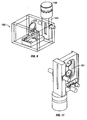
Figure 11 is a schematic of a process station with a holder for two disks; and, -
Figure 12 is a chart showing a cycle of operation of the system. - A prior art substrate processing system is shown in
Figure 1 where like elements have the same reference numerals. As shown inFigure 1 , the system includes aprocessing unit 10 and asubstrate handling system 20. Theprocessing unit 10 includes a plurality ofprocess stations main vacuum chamber 40.Process stations main vacuum chamber 40. Processingunit 10 further includes aloading station 42 for loading substrates into the system for processing and an unloadingstation 44 for unloading substrates from the system following processing. The substrates are typically substrates for making magnetic hard disks or for making magnetic optical disks. The substrates and ultimate disks include a central opening. The substrate processing system may further include vacuum pumps, power supplies and a controller (not shown). - Processing is carried out in the
different process stations Figure 1 , the system has twelve process stations, loadingstation 42 and unloadingstation 44, which are equiangularly spaced. The process stations may comprise a one or more heating stations, sputter stations, cooling stations, chemical vapor deposition stations and the like, as are employed in the art in manufacturing magnetic disks. The substrates are moved through the system as to serially transfer to and be processed by the process stations, one after another and for the same amount of time at each station. The substrate holder also seals the process station from the main vacuum chamber during processing operations as to avoid contamination within the process stations and the central chamber. - Within
main vacuum chamber 40 there are positioned a plurality of substrate grippers, or disk grippers, positioned in respect to each process station such that they may be raised into the respective process stations. Thesubstrate handling system 20 includes abuffer vacuum chamber 90, aload lock 92, anentrance conveyor 94, an unloadlock 96 and anexit conveyor 98.Cassettes buffer vacuum chamber 90 throughload lock 92 and exit frombuffer vacuum chamber 90 through unloadlock 96. Aload arm 102, in this configuration, transfers substrates fromcassette 100b to disk gripper orlifter 70 inloading station 42. An unloadarm 104 transfers substrates from disk gripper ordisk lifter 70 in unloadingstation 44 to cassette 100c.Substrate handling system 20 is described in detail in the aforementioned Patent No. 5,215,420, which is hereby incorporated by reference. - In
Figure 2 , there is shown a preferred embodiment of a system in accordance with this invention. This comprises a number of process stations in a stacked relationship, with a second layer of process stations positioned on top of a base layer of process stations. It is a system without the large central vacuum main chamber that is found in the prior art system illustrated inFigure 1 . It permits controlled cycling for substrates being processed travelling through the system. It considerably reduces the footprint occupied by systems in the prior art and enables more process stations. It therefore permits a greater number of process operations on substrates passing through the system or in a much smaller footprint the same number of operations as may have been performed in a prior art unit with a significantly larger footprint. Further, each process station is separately pumped by an attached vacuum pump such as a turbo-molecular or cryo-pump as to create an independent atmosphere for processes performed at each station as will be illustrated and discussed in connection with subsequent figures. - Referring now to
Figure 2 , a 23 station processing system is illustrated. In fact the number of stations could be more or less than this number. The stations are identified as 101-123. To load the system identified as 125, a cassette of substrates is fed into the load/unloadaperture 126. The cassette travels along a path into position at load/unloadstation 129. A disk carrier (seeFigure 4A ) moves into the load/unloadchamber 129 where a transfer mechanism, on the unload side, grips a disk in the disk carrier that had been through the processing cycle, by its inner hole. The jaws of the disk carrier are then opened and the processed substrate is removed from the disk carrier and transferred to a lift blade similar to the one described as prior art in connection withFigure 1 . The lift blade then places the substrate or disk into a cassette. In this same load/unloadstation 129 but from the load side, a lift blade, again like the one used in the prior art, lifts a substrate or disk from the cassette and raises it into the load chamber. A transfer mechanism transfers the disk from the lift blade and transfers it to the disk carrier wherejaws Figure 4A ). The disk carrier then moves to anelevator 128 and is lifted (as illustrated) to a level adjacent to the upper set of process stations and directly adjacent tostation 101. The substrate and carrier then move as a unit and transfer intostation 101 where processing of the disk is started. Thereafter, the combined unit of asubstrate 130 and a disk carrier, move into theadjacent processing station 102. After processing atstation 102, the substrate and disk carrier move on to theadjacent station 103 where the disk is carried through additional processing operations. The substrate on the disk carrier travel from one processing chamber to the next along the upper level in series from 101 to 112 where the combined unit enterselevator 131. The combined unit is then lowered to the lower lever along which it travels fromstation 123 back tostation 113. Along the way the disk is processed in accordance with the needs and desires of the manufacturing facility. For example, since substrates entering the system are in a sense water logged when considering the process to which the disk will be exposed, the elevator chamber may include a cold trap, such as a water pump or a Meisner trap to remove moisture from the disk and the vacuum system. At thefirst station 101, the disk may be heated to continue its preconditioning prior to being carried through coating processing. - Power controls 132 are positioned as shown above and below the processing stations. They may however, be located at the ends of the system. In the instance where the system requires a large number of controls for power intensive processes, the controls may be positioned in separate cabinets. The system is programmed and driven by entries at an
operator station 133 at the left side ofsystem 125 as shown inFigure 2 but shown more clearly inFigure 6A . Althoughstation 127 is described as a load/unload station, it may in fact act only to load substrates into the system with the unload operation performed at the other end, for example, adjacent tostation 123. An unload station would be found on the backside of the unit shown inFigure 2 in a position opposite the load station on the facing side. This will be shown more clearly in a subsequent figure. In essence it looks like the load station but functions to unload the system. A disk carrier with a disk or substrate in place moves into the unload chamber. A transfer mechanism takes the disk fromjaws 134 and 139 (seeFigure 4 ) which open and release the disk to the transfer mechanism. The transfer mechanism may be a system as is used on the structure ofFigure 1 or as subsequently discussed. This mechanism transfers the disk to the unload blade (which may conform to the load blade as used at the load station and also to the load blade used in connection withFigure 1 ), where the disk is lowered into the load side of a cassette. -
Figure 2 illustrates asystem 125 with 23 stations. However, if the manufacturer of a particular magnetic disk requires less processes be performed during the production of the finished disk, a full system of 23 or more stations may not be required or the substrates, in such a case, can be directed and controlled to move only through a limited group of active process stations or less than all the process stations can be operational. Alternatively, a smaller system can be used. Such a system could for example include less process stations. It is also possible to marry a stacked system with systems that rely on a central vacuum chamber and have a circular configuration. A benefit to such a structure is that it enables the existing manufacturers to tie their existing units to the system of this invention as to enable additional or new processes to be performed in making magnetic disks in a limited additional area or footprint. This will be further discussed in connection withFigure 6 below. - In
Figure 3 is shown asingle process module 135 and inFigure 4A , adisk carrier 136 is illustrated with asubstrate 130 in place. InFigure 4B there is shown the mechanism to transfer disks into the carrier at the load station and to transfer disks out of the disk carrier at the unload station. InFigure 4C there is shown another view of the mechanism inFigure 4B with more detail in connection with the disk carrier and the arrangement of the disk on the carrier. -
Disk carrier 136, is shown in position inFigure 3 inprocess module 135.Isolation valve 144 andisolation valve driver 145 operate to close andopen opening 129 of thechamber 135. Thesubstrate 130 is positioned into the disk carrier and held in place in the disk carrier throughout its travels. It is released following processing in the various processing chambers by a transfer mechanism that grips the disk by its inner hole and a gripper actuator and a gripper actuator mechanism that opens the carrier jaws after the disk is gripped for unloading or before the disk is ungripped for loading. These manipulations are illustrated inFigure 4B and 4C . - In
Figure 4B acassette 202 of substrates has been fed intotransfer section 201 through theload door 204. At this point the substrates are in the vacuum environment. The substrates will remain in a vacuum environment for all manipulations from this point on until the processed substrates leave thetransfer station 201 by being unloaded at the unloadzone 207 back into a cassette and removed from the transfer station and the equipment in a cassette holder through the unloaddoor 208. A cassette ofdisks 202 is shown in position at the load section of this subsystem. The cassette holder rides onwheels 206 that transport the cassette holder into position to place substrates into position to be lifted out ofcassette holder 202, upwardly throughtransfer zone 203 and todisk loading zone 205 where the substrates are loaded into the disk carrier. As has been described the disk is lifted out of the cassette by a disk lifter similar to the lifter used in the prior art system illustrated inFigure 1 . In this case the lifter travels up throughopening 222 and then through the cassette where it engages a substrate and then lifts the substrate throughtransfer zone 203 and intodisk loading zone 205. A similar lifter is employed to transfer coated substrates back to the cassette 224 receiving substrate which when fully loaded exits transferstation 201. The lifter takes a substrate from the unload zone and moves down through the path on the unload side and then through the cassette where the substrate remains as the lifter arm moves on throughopening 223. - A substrate that arrives in the load zone in initially in a position above the
transfer zone 203. At that point a pick-uparm 210 moves outwardly and into the hole in the middle of the substrate. Thisarm 210 connects to the substrate by clips that are inserted into the center section of the substrate and there grasp the inner edges of the substrate center hole or opening. Thearm 210 then moves back to the position shown in this Figure where it actuates amechanism 211 which in turn opens the jaws of a disk carrier. The disk carrier jaws are then positioned around the disk or substrate, remove the disk from the pick-up arm, and grasp the disk to carry it through the various processes of the equipment -
Figure 4C is a side view of this disk load/ unload section shown InFigure 4B in this Figure adisk carrier 136 is shown in side view. In thisview wheels 137 located in thetransport drive section 212 are in view. The wheels are used to transport the disk carrier throughout the systems. Disk carriers are moved from process chamber to process chamber by amagnetic drive system 212 in part, located at the base of each chamber and in part, as a mating structure located on the base of eachdisk carrier 216. Each disk carrier and each chamber have independent transport elements for operation with themagnetic drive system 212. The wheels for this system are driven by an ordinary motor utilizing a rotary vacuum feed through but they may be replaced by a linear motor. The disk carriers are moved by way of a soft magnetic material, such as 400 series stainless steel mounted in thecarrier base 216. Illustrated in the lower section ofFigure 4C is the side view of thecassette 202 in the lower chamber. - Also shown are the
magnet actuating systems 211 that are energized to open thedisk carrier 136 as to permit the insertion of asubstrate 130 or to release a processed substrate in the unloadzone 207. Four such magnets are shown. However fewer or more may be used to accomplish the purpose of opening and closing the jaws of the substrate holder. - Around the substrate is a
halo structure 213. This structure is attached to thedisk carrier 136 and permits the processing of substrates of different diameters. For example the halo structure can be widened or narrowed or even removed from the disk carrier as to permit the positioning of varying sized substrates in the holder for processing. The disk or substrate in position in the disk carrier is held at its edges by thehalo structure 213 or if none is in use then by thedisk carrier 136 itself. -
Figures 5A shows the structure of atypical process chamber 135 in which processing operations are performed insystem 125. The disk holder positions disks in the upper opening. Thesides 140 when fully assembled include isolation seals to isolate the chamber from adjacent chambers and the rest of the system. A cold trap, vacuum pump or instrumentation may be placed at thetop opening 142. The primary vacuum pump for a chamber is positioned adjacent to the chamber on the isolation valve body (shown inFigure 5B ) and pumping is throughopening 140. In the preferred embodiment each chamber has its own cryo, turbo or other suitable pump to maintain uniform and controlled vacuum environments in each of the chambers. The front opening as well as the back opening are used for example in connection with a chamber doing sputter deposition, to position sources with targets on each side of the substrate being coated or processed. Other processing devices may also be positioned at these openings as to become chamber walls enclosing the processing chamber. At the openings at the base there are positioned the wheels and lower section of the disk carrier, a seal to close off openings and drivemotors 163 for the transport. -
Figure 5B illustrates a processing station showing elements in place. At the top is shown theturbo pump 149 with 2sputtering sources 143 mounted on thechamber frame 135. Also seen in this figure isisolation valve 144 which seals this chamber on its right side. On the left side an opening 129is shown to fit this chamber against other chambers or to an elevator. An adjacent chamber would normally have an isolation valve on the side fitted to this chamber so that the chambers are isolated from each other. - Referring now to
Figure 6A there is illustrated astacked system 146 connected to acircular system 147. This combined unit may comprise a complete processing system or may illustrate the addition of more process capabilities to existing circular units by providing stacked process stations feeding to or from systems like those presently in use commercially in the art and illustrated inFigure 1 . In this unit, thecircular portion 147, withprocess stations 151, is supported byrails 144, processes substrates sequentially by moving the substrates fromchamber 151 to a next chamber. The first section of thisunit 146 illustrates process stations in a line. These can be identified by thevacuum pumps 149 attached at the upper portion of the process chambers. Although three upper processing chambers are illustrated, it should be understood that a system may comprise more or less of such stations depending on the needs and/or the desires of the user. Also although not seen inFigure 6A , thissection 146 may include a lower layer of process stations beneath those appearing connected tovacuum pumps 149. This is shown inFigure 6B . A vacuum pump exists for each process chamber. Similar vacuum pumps extend below the process chambers for process chambers at the lower portion of the stack at 146. Again this is seen inFigure 6B . A screen 148 andkeyboard 150comprise operator station 133 to control operation of the equipment. Thecircular configuration 147 includes single processing chambers with vacuum pumps attached. If the stackedfront end section 146 is attached to a system like that shown inFigure 1 , the substrate in the disk carrier ofsection 146 will transfer disks into the substrate handling system ofFigure 1 or todisk gripper 70 at loadingstation 42 to thereafter be fed into and through the system. -
Figure 7 A-E , is a set of diagrams illustrating how disks may be moved through the stacked system illustrated for example inFigure 2 ..Figure 7 comprises five different diagrams. Illustrated is how the arrangement of disks as they enter a process chamber and then how the disks are transferred between stations. The disks are numbered 1-5, and 18-25 for purposes of following movement from place to place in the diagrams. Thus inFigure 7A ,disk 1 is in position in the lower or entry section ofelevator 128 anddisk 2 is at the entry station.Substrates Figure 7B the elevator movesdisk 1 to the top level into a position to enter into the processing chambers for processing anddisk 18 exits and is separated from its disk carrier as is described in connection withFigures 4 A-C . It is then loaded into an unload cassette.Disk 2 in this Figure is being loaded into a disk carrier in the load station again in accordance with the discussion in connection withFigures 4 A-C . InFigure 7C disk 1 is moved in a disk carrier into a first process station whiledisk 2 mounted into a disk carrier moves into the elevator and 18, a completed coated substrate is moved out of the system.Disk 3 is positioned for entry into the system anddisk 19 is being readied to exit and is being separated from its disk carrier. The other disks shown inFigure 7C are shown moved through the system. Thus at the top layer of processing stations,disks Figure 7B ) anddisk 1 moves into a processing station. The disk at the final position of the top layer at the right moves downwardly so thatdisk 22 now occupies the last position on the right of the lower layer while the other disks on the lower layer move one station each to the left. InFigure 7D anew disk 4 is getting ready to enter the system whiledisk 20 is about to exit the system. Again the top layer of disks have all moved one station to the right and the end disk, disk 23 (Figure 7C ) moves down to the station below (Figure 7D ). InFigure 7E disk 5 is shown entering the system,disk 4 mounted in a disk carrier is on the elevator and ready to move up to the entry station now occupied bydisk 3. The disks move over and down following the route illustrated in the previous figures anddisk 20 moves out of the system. At this point in the cycle for this structure and program, all theoriginal disks Figure 7A have entered and 3new substrates disks - Referring now to
Figures 8A-E , the equipment is shown in two parts with a swing arm to move substrates from one part to the other. Again the substrates have been numbered to simplify following their paths and travel. InFigure 8A substrates Substrates Substrate 12 joins the completed substrates inFigure 8B andsubstrate 25 is moved byswing arm 153 from a group of stacked processing stations at the left to another at the right. InFigure 8 E substrates Figures 8A-E . - In
Figure 9 there is shown acarrier exchange module 156. Carriers present during processing of substrates at various process stations become coated with materials being deposited at the process stations. For example, in a typical manufacturing process, to create magnetic hard disks, a substrate of aluminum may be initially coated using sputtering techniques with a chromium layer followed by the deposition of a cobalt alloy followed thereafter by the deposition of other layers as determined by the user in accordance with its process of manufacture, frequently proprietary, to manufacture magnetic disks. A final area of deposition may be based on creating a diamond like coating using, for example, a plasma enhanced chemical vapor deposition to deposit carbon, as for example is disclosed and discussed inU.S.6,368,678 B1 . Thus in a system in which chromium, cobalt and carbon are all deposited on the same substrate, there results a build-up of unwanted materials on the carrier if the same carrier is used in each of the processes. This in itself might not be a problem. However, a problem is created if the deposited materials on the carrier flake off during a subsequent process step so that the new deposition onto the partially coated substrate is disrupted or poisoned as to make the end product not dependable and/or not consistent with other produced output. To prevent this problem from arising, the system of this invention includes stations strategically positioned to permit the carrier to be changed to a fresh and clean carrier before further processing of the substrate takes place.Figure 9 illustrates such an exchange module andFigure 10 A-D illustrates a carrier exchange sequence. To start with aclean carrier 155 is loaded into theexchange module 156. The clean carrier may be loaded into this module by hand or alternatively by automatically feeding new carriers as programmed into the system to occur after a set number of uses of a carrier in process stations or a set number of exposures of carriers to particular process steps and/or depositions. A clean carrier in the carrier exchange module is first preconditioned so that impurities have been removed before they have had a deleterious effect on subsequent operations and on the coated substrate itself. The carrier exchange module may be placed at the end of the in-line structure, at either end or at both ends or in an equivalent position. For example it could be beyond the elevators as illustrated inFigure 8A where the stations are identified as 156 and 159. A like station can also be placed at the point of the swing arm shown inFigures 8 A-E , This structure permits the changing of disk carriers as the disk is moved from a first section to a second section of the process chambers so that when the disk enters the second section it can enter with a pre-cleaned disk carrier to effectively insulate the disk from the processes in the first section of the unit. Also when positioned as illustrated inFigure 8A , a disk carrier may be transferred out of service by entering the module for cleaning following the transfer of a disk from the disk carrier. InFigure 9 there is illustrated avacuum pump 149 and anisolation valve 144. These enable thecarrier exchange module 156 to connect directly into the system without causing corruption. Such a structure can be positioned as shown inFigure 8A at 156 or 159 or may also be positioned to replace disk carriers at the point of the swing arm or at any other point where contamination will follow if the carrier is not changed. The system shown inFigure 6A , if connecting to existing equipment, requires a hand off of the disk apart from the disk carrier when the disk moves from the inline equipment 146 where it travels in a disk carrier to thecircular version 147 where the disk may be lifted from the disk carrier or from a cassette into which the disk is placed on entry into thecircular portion 147 of the system. When the disk is positioned on a lifter it is then handed over to a carrier as used in the prior art, in the nature of a pedestal, that moves with the disk through the system until transferred back to a lifter to take the disk back to a cassette or to hand the disk over to a disk carrier for further processing in the in line part of thesystem 146. Thus astation 156 such as is shown inFigure 9 can be provided at this point to separate the disk from the carrier as the disk completes its travels throughsection 146 and enters 147. Similarly, when the disk completes its travels throughsection 147 and is to reentersection 146, the disk can be reinstalled into a clean disk carrier at a station like that inFigure 9 . - In
Figure 10 a carrier exchange module is shown in a position beyondelevator 128. The system inFigure 10 is programmed to skip load a carrier when the new carrier is ready. Thenew carrier 155 is used to replace the skip loadedcarrier 157. This is illustrated by theempty carrier 157 in the initial chamber. The empty carrier follows a normal sequence of travelling upward inelevator 128. This is shown inFigure 10B . In 10C there is illustrated the exchange of carriers. Theclean carrier 155 replaces the carrier being exchanged 157 and as shown inFigure 10D the clean carrier moves into the normal flow cycle and the new carrier requiring cleaning 157 is cleaned and then is inserted into the exchange module to be used to replace the next carrier requiring renewal. - Referring now to
Figure 11 , there is illustrated a disk carrier which holds two disks at the same time. This is achieved using agripping mechanism 161 that holds two disks in position for processing in the various process chambers as the disk carrier moves through the system. This design can double the throughput of the system since the same time will be consumed in each process chamber whether there are two or one disk in the disk carrier. -
Figure 12 illustrates a cycle that is useable with thesystem 125 illustrated inFigure 2 . This cycle is based on 5.1 seconds per operation. One second is used for transport and 4.1 seconds are used for processing. These times can obviously be varied butsystem 125 is operable in accordance with these time constraints. Operating at these speeds results in the production of 700 coated substrates per hour and operating a normal eight hour day produces in excess of a million and a half disks per month. - Although processing in the process stations has not been discussed extensively, it should be understood that this equipment offers real advantages in this respect. For example. a disk carrier may enter a process station and be continuously moved through a number of process stations during processing. This is known as pass by processing. This has an advantage for certain types of depositions. It is also possible to tie two or more processing stations together and process substrates for more time in the same processes. Thus instead, for example, of using 2 or more process stations to bring a substrate to temperature, two or more process stations can be combined into a single larger process station as to perform the desired function in a single station or the equivalent of a single station that normally requires considerable movement and multiple stations for the same results. Also, whereas the processing time usually used for a cycle is about 5 seconds, this can be either a very short period and too short a time for certain process operations or a long period for some process operations and thus the equipment can be programmed for varying operations. This can be dealt with in the equipment of this invention by combining process stations into a larger station as to allow the disk carrier to dwell longer in a station and permit processes that may require two or three time the amount of time required for other operations or it may be achieved by slowing down the cycle provided those operations requiring less time are properly adjusted.
- Although a preferred embodiment of this invention has been described and illustrated, it should be understood by those skilled in the art that various changes and modifications may be made without departing from the scope of the invention as defined in the appended claims.
Claims (21)
- A substrate processing system (125) for the processing of substrates comprising:an entryway (127, 129, 201) to feed substrates (130) into the processing system (125);processing stations (101-112, 113-123) aligned adjacent with one another to process substrates (130) while substrates are maintained In a vertical orientation;carriers (136, 155) to carry substrates (130) into processing stations (101-123) and to hold substrates (130) in a vertical position as substrates are processed and move through said processing stations and from station to station (101-123);a transfer device (129, 134, 139) to transfer substrates entering the processing system Into carriers;transport paths and drives to move (128) carriers from processing station to processing station and to an unload zone (126), said unload zone being operable to remove processed substrates from said carrier after processing and to position the processed substrates to be transported out of said system (129);characterized by said transport paths and drivers comprising a magnetic drive system (212) for said carriers located in part at each of said processing stations (101-112, 113-123) and in part on each of said carriers (136, 155).
said processing stations being positioned in a stacked relationship with at least a second layer (101-112) of processing stations positioned above a first layer of processing stations (113-123) so that the footprint for two processing stations is substantially not greater than the footprint for one processing station and less than the footprint of two processing stations positioned one following the other lengthwise;
an elevator (128, 131) to raise and/or lower substrates (130);
Isolation valves (144) fitted to each said processing station (101-123) to isolate each station during processing therein; and - A substrate processing system in accordance with claim 1 in which said second layer (101-112) of processing stations is positioned on top of said first layer (113-123) of processing stations and in which the processes practiced in said processing stations manufacture magnetic hard disks
- A substrate processing system in accordance with claim 1 In which said second layer (101-112) of processing stations is positioned on top of said first layer (113-123) of processing stations and in which the processes practiced in said processing stations manufacture magneto-optical disks.
- A substrate processing system in accordance with claim 1,2 or 3 including a carrier exchange station positioned along the path of travel through said processing stations (101-112,113-123) by a carrier to furnish clean replacement carriers for a carrier that has been exposed to coating processes in said system.
- A substrate processing system in accordance with claim 1,2,3 or 4 in which the path of travel of a carrier is from processing station to adjacent processing station in sequence and from a first level to the second level following processing at said first level in an elevator.
- A substrate processing system in accordance with claim 4 in which said carrier exchange station is positioned at the start of a process sequence at the initial level for processing and in which a clean carrier is substituted for a carrier that has completed cycles and otherwise would have accepted and sequenced a new incoming substrate.
- A substrate processing system in accordance with claim 4 in which said carrier exchange station is positioned at a point in the process sequence following processing of substrates with processes that result in deposits on the carrier that can poison later processes and in which a clean carrier can be substituted for a carrier with depositions on its surface.
- A substrate processing system in accordance with claim 5 In which the path of travel of a carrier is into an elevator to raise the carrier to the upper level and then from processing station to adjacent processing station in sequence on said upper level and from said upper level to the lower level following processing In said upper level in a lift.
- A substrate treatment system in accordance with claim 1, in which a carrier in a process station is continuously moved while being processed In said station.
- A substrate treatment system in accordance with claim 1, in which one or more process stations are Internally connected as to enable a substrate on a carrier placed within any such station to be processed In accordance with the processes practiced within said stations for a period of time substantially equal to the time of processing within a single process station in the system times the number of connected process stations.
- A processing system in accordance with claim 1, in which said carriers each carry more than a single substrate.
- A substrate processing system in accordance with any one of claims 1 to 11 in which said magnetic drive system (212), in part, is located at the base of each processing station and in part, as a mating structure on the base (216) of each carrier (136).
- A substrate processing system in accordance with any one of claims 1 to 12 including a linear motor for transporting the carrier 176.
- A substrate processing system in accordance with any one of claims 1 to 13 in which wheels (137) and a soft magnetic material are located at the base (216) of the carrier.
- A substrate processing system in accordance with claim 1, in which a carrier (136, 155) in a process station (135, 151, 156, 159) is maintained stationary while a substrate (130) in said carrier (126,155) is being processed in said station.
- A substrate processing system in accordance with any one of claims 1 to 14 in which a carrier (136, 155) in a process station (101-123, 138, 151, 156, 159) is moved during processing.
- A processing system in accordance with any one of claims 1 to 16 in which a vacuum pump (149) is connected to each processing station.
- A processing system in accordance with any one of claims 1 to 16 in which a cold trap is attached to each processing station (101-123).
- A processing chamber (101-123) for a substrate manufacturing system fitted to be positioned in a stacked relationship with another substrate processing chamber and comprising a vacuum pump (149) extending from the chamber 101-123 to pump a vacuum in said chamber (101-123), an opening (129) at one side of said chamber (101-123) to be positioned attached to an adjacent chamber, characterized by an isolation valve (144) to isolate said chamber (101-123) from other chambers in a system during processing within said chamber (101-123), magnetic means (212) located in part at the base of said chamber (101-123) and in part on a substrate carriers (216) to assist in the transport of the substrate carrier (216) into and out of said chamber (101-123), process sources (143) positioned on the front and back walls of said chamber (101-123) to enable processing of both sides of a substrate (130) positioned within said chamber (101-123), and the arrangement being such that a similar chamber is positionable in a stacked relationship with said chamber (101-123) to enable actively processing another substrate in a substrate carrier in said similar chamber during processing or transport of a carrier In said upper substrate processing chamber (101-123).
- A method of manufacturing a processed substrate in a plurality of processing chambers, including a first processing chamber and a second processing chamber, the method comprising:placing a substrate (130) to be processed into a load system (129), lifting said substrate (130) to a load chamber (205) and loading said substrate into a carrier (136) at said load chamber, moving said substrate (130) and carrier (136) to at least the first processing chamber at a first level (212) and processing said substrate in said first processing chamber,changing the elevation of said substrate and said carrier to a different level (131), moving said substrate and said carrier into at least the second a processing chamber at said new level (123),isolating said first processing chamber during processing therein from the other ones of said processing chambers by an isolation valve (144), isolating said second processing chamber during processing therein from the other ones of said processing chambers by an isolation valve (144),characterized by moving the carrier (136) from chamber to chamber by a magnetic drive system located in part at each of said processing stations (101-112, 113-123) and in part on each of said carriers (136, 155), and by removing moisture from the substrate while in said elevator.
- The method of claim 20 including substituting a clean carrier (155) for a coated carrier to avoid contamination of the substrate in processing stations located following the change in carriers.
Applications Claiming Priority (3)
| Application Number | Priority Date | Filing Date | Title |
|---|---|---|---|
| US10/361,308 US6919001B2 (en) | 2000-05-01 | 2003-02-10 | Disk coating system |
| US361308 | 2003-02-10 | ||
| PCT/US2004/001155 WO2004072959A2 (en) | 2003-02-10 | 2004-01-20 | Disk coating system |
Publications (3)
| Publication Number | Publication Date |
|---|---|
| EP1592822A2 EP1592822A2 (en) | 2005-11-09 |
| EP1592822A4 EP1592822A4 (en) | 2006-05-24 |
| EP1592822B1 true EP1592822B1 (en) | 2009-07-29 |
Family
ID=32867955
Family Applications (1)
| Application Number | Title | Priority Date | Filing Date |
|---|---|---|---|
| EP04703559A Expired - Lifetime EP1592822B1 (en) | 2003-02-10 | 2004-01-20 | Disk coating system |
Country Status (7)
| Country | Link |
|---|---|
| US (1) | US6919001B2 (en) |
| EP (1) | EP1592822B1 (en) |
| JP (5) | JP2006517324A (en) |
| KR (2) | KR100761187B1 (en) |
| CN (1) | CN1798862A (en) |
| DE (2) | DE602004022257D1 (en) |
| WO (1) | WO2004072959A2 (en) |
Families Citing this family (74)
| Publication number | Priority date | Publication date | Assignee | Title |
|---|---|---|---|---|
| JP3555844B2 (en) | 1999-04-09 | 2004-08-18 | 三宅 正二郎 | Sliding member and manufacturing method thereof |
| US8382902B2 (en) * | 2000-04-12 | 2013-02-26 | Seagate Technology Llc | Single disc vapor lubrication |
| US6808741B1 (en) * | 2001-10-26 | 2004-10-26 | Seagate Technology Llc | In-line, pass-by method for vapor lubrication |
| US6995121B1 (en) * | 2002-06-24 | 2006-02-07 | Seagate Technology Llc | Stability polymeric lubricants and thin film recording media comprising same |
| US7684895B2 (en) | 2002-08-31 | 2010-03-23 | Applied Materials, Inc. | Wafer loading station that automatically retracts from a moving conveyor in response to an unscheduled event |
| US7243003B2 (en) | 2002-08-31 | 2007-07-10 | Applied Materials, Inc. | Substrate carrier handler that unloads substrate carriers directly from a moving conveyor |
| US7930061B2 (en) | 2002-08-31 | 2011-04-19 | Applied Materials, Inc. | Methods and apparatus for loading and unloading substrate carriers on moving conveyors using feedback |
| US7234584B2 (en) * | 2002-08-31 | 2007-06-26 | Applied Materials, Inc. | System for transporting substrate carriers |
| US7506746B2 (en) | 2002-08-31 | 2009-03-24 | Applied Materials, Inc. | System for transporting substrate carriers |
| US20040081546A1 (en) | 2002-08-31 | 2004-04-29 | Applied Materials, Inc. | Method and apparatus for supplying substrates to a processing tool |
| US20050095110A1 (en) * | 2002-08-31 | 2005-05-05 | Lowrance Robert B. | Method and apparatus for unloading substrate carriers from substrate carrier transport system |
| JP2004138128A (en) | 2002-10-16 | 2004-05-13 | Nissan Motor Co Ltd | Sliding members for automobile engines |
| US6969198B2 (en) | 2002-11-06 | 2005-11-29 | Nissan Motor Co., Ltd. | Low-friction sliding mechanism |
| JP3891433B2 (en) | 2003-04-15 | 2007-03-14 | 日産自動車株式会社 | Fuel injection valve |
| EP1479946B1 (en) | 2003-05-23 | 2012-12-19 | Nissan Motor Co., Ltd. | Piston for internal combustion engine |
| EP1482190B1 (en) | 2003-05-27 | 2012-12-05 | Nissan Motor Company Limited | Rolling element |
| JP2004360649A (en) | 2003-06-06 | 2004-12-24 | Nissan Motor Co Ltd | Engine piston pin |
| JP4863152B2 (en) | 2003-07-31 | 2012-01-25 | 日産自動車株式会社 | gear |
| CN101760286B (en) | 2003-08-06 | 2013-03-20 | 日产自动车株式会社 | Low friction sliding mechanism, low friction agent composition, and method of reducing friction |
| JP4973971B2 (en) | 2003-08-08 | 2012-07-11 | 日産自動車株式会社 | Sliding member |
| JP2005054617A (en) | 2003-08-08 | 2005-03-03 | Nissan Motor Co Ltd | Valve mechanism |
| JP4117553B2 (en) | 2003-08-13 | 2008-07-16 | 日産自動車株式会社 | Chain drive |
| DE602004008547T2 (en) | 2003-08-13 | 2008-05-21 | Nissan Motor Co., Ltd., Yokohama | Structure for connecting a piston to a crankshaft |
| JP4539205B2 (en) | 2003-08-21 | 2010-09-08 | 日産自動車株式会社 | Refrigerant compressor |
| US7771821B2 (en) | 2003-08-21 | 2010-08-10 | Nissan Motor Co., Ltd. | Low-friction sliding member and low-friction sliding mechanism using same |
| EP1508611B1 (en) | 2003-08-22 | 2019-04-17 | Nissan Motor Co., Ltd. | Transmission comprising low-friction sliding members and transmission oil therefor |
| JP4447279B2 (en) * | 2003-10-15 | 2010-04-07 | キヤノンアネルバ株式会社 | Deposition equipment |
| TWI367192B (en) * | 2003-11-13 | 2012-07-01 | Applied Materials Inc | Calibration of high speed loader to substrate transport system |
| US7682653B1 (en) * | 2004-06-17 | 2010-03-23 | Seagate Technology Llc | Magnetic disk with uniform lubricant thickness distribution |
| US7678198B2 (en) * | 2004-08-12 | 2010-03-16 | Cardinal Cg Company | Vertical-offset coater |
| CN100550286C (en) * | 2004-09-10 | 2009-10-14 | Oc欧瑞康巴尔斯公司 | Substrate Processing System |
| US7438175B2 (en) * | 2005-06-10 | 2008-10-21 | Applied Materials, Inc. | Linear vacuum deposition system |
| US20080197015A1 (en) | 2007-02-16 | 2008-08-21 | Terry Bluck | Multiple-magnetron sputtering source with plasma confinement |
| JP5006122B2 (en) | 2007-06-29 | 2012-08-22 | 株式会社Sokudo | Substrate processing equipment |
| JP4794514B2 (en) * | 2007-07-11 | 2011-10-19 | 昭和電工株式会社 | Method and apparatus for manufacturing magnetic recording medium |
| JP4820783B2 (en) * | 2007-07-11 | 2011-11-24 | 昭和電工株式会社 | Method and apparatus for manufacturing magnetic recording medium |
| US7770714B2 (en) * | 2007-08-27 | 2010-08-10 | Canon Anelva Corporation | Transfer apparatus |
| US8834088B2 (en) | 2007-11-12 | 2014-09-16 | Intevac, Inc. | Elevator linear motor drive |
| JP5128918B2 (en) | 2007-11-30 | 2013-01-23 | 株式会社Sokudo | Substrate processing equipment |
| JP2011507131A (en) * | 2007-12-06 | 2011-03-03 | インテバック・インコーポレイテッド | System and method for commercially producing patterned media |
| WO2009085840A2 (en) * | 2007-12-28 | 2009-07-09 | Lam Research Corporation | Wafer carrier drive apparatus and method for operating the same |
| JP5179170B2 (en) | 2007-12-28 | 2013-04-10 | 株式会社Sokudo | Substrate processing equipment |
| JP5001828B2 (en) | 2007-12-28 | 2012-08-15 | 株式会社Sokudo | Substrate processing equipment |
| JP4746063B2 (en) * | 2008-02-18 | 2011-08-10 | キヤノンアネルバ株式会社 | Film forming apparatus and stock chamber for film forming apparatus |
| US8382965B2 (en) * | 2008-05-09 | 2013-02-26 | Intevac, Inc. | Tools and methods for mounting transport rails in a substrate processing system |
| US20090304907A1 (en) * | 2008-06-09 | 2009-12-10 | Applied Materials, Inc. | Coating system and method for coating a substrate |
| EP2133445B1 (en) * | 2008-06-09 | 2012-08-08 | Applied Materials, Inc. | Coating System and Method for Coating a Substrate |
| CN102057076B (en) * | 2008-06-09 | 2013-03-06 | 应用材料公司 | Coating system and method for coating a substrate |
| CN101635253A (en) * | 2008-06-14 | 2010-01-27 | 因特维克有限公司 | System and method for processing substrates with detachable mask |
| JPWO2009153856A1 (en) * | 2008-06-17 | 2011-11-24 | キヤノンアネルバ株式会社 | Carrier with protective cover and protective cover attaching / detaching device |
| EP2141739A3 (en) | 2008-06-30 | 2011-01-12 | Intevac, Inc. | System and method for substrate transport |
| WO2010014761A1 (en) | 2008-07-29 | 2010-02-04 | Intevac, Inc. | Processing tool with combined sputter and evaporation deposition sources |
| US9343273B2 (en) * | 2008-09-25 | 2016-05-17 | Seagate Technology Llc | Substrate holders for uniform reactive sputtering |
| JP4377452B1 (en) * | 2008-09-30 | 2009-12-02 | キヤノンアネルバ株式会社 | Substrate holder storage chamber, inline-type substrate processing apparatus, and magnetic disk manufacturing method |
| US8697189B2 (en) | 2008-10-21 | 2014-04-15 | Intevac, Inc. | Method and apparatus for precision surface modification in nano-imprint lithography |
| JP5529484B2 (en) * | 2008-10-28 | 2014-06-25 | キヤノンアネルバ株式会社 | Substrate transport apparatus and magnetic recording medium manufacturing method |
| US20110263065A1 (en) * | 2010-04-22 | 2011-10-27 | Primestar Solar, Inc. | Modular system for high-rate deposition of thin film layers on photovoltaic module substrates |
| TW201137142A (en) * | 2010-04-28 | 2011-11-01 | Hon Hai Prec Ind Co Ltd | Sputtering device and sputtering method |
| SG11201403609QA (en) * | 2011-12-27 | 2014-07-30 | Intevac Inc | System architecture for combined static and pass-by processing |
| US20130340939A1 (en) * | 2012-06-21 | 2013-12-26 | Tel Solar Ag | System for substrate handling and processing |
| CN102936100B (en) * | 2012-11-29 | 2014-12-17 | 肇庆市科润真空设备有限公司 | Rotary type continuous coating device and method thereof |
| CN106103791B (en) | 2014-01-17 | 2019-06-07 | 希捷科技有限公司 | Etch sources that can be installed in storage media processing tools |
| CN103993273B (en) * | 2014-05-09 | 2016-01-27 | 浙江上方电子装备有限公司 | A kind of sound the admixture plates the film system and utilize it to carry out the method for sound the admixture plates the film |
| CN106661722A (en) * | 2014-07-31 | 2017-05-10 | 株式会社爱发科 | Substrate processing device |
| WO2017066449A1 (en) | 2015-10-14 | 2017-04-20 | Qorvo Us, Inc. | Multi-stage deposition system for growth of inclined c-axis piezoelectric material structures |
| US10571437B2 (en) | 2015-12-15 | 2020-02-25 | Qorvo Us, Inc. | Temperature compensation and operational configuration for bulk acoustic wave resonator devices |
| KR102519797B1 (en) * | 2016-04-12 | 2023-04-10 | 삼성디스플레이 주식회사 | Deposition apparatus and deposition |
| US11824511B2 (en) | 2018-03-21 | 2023-11-21 | Qorvo Us, Inc. | Method for manufacturing piezoelectric bulk layers with tilted c-axis orientation |
| US11381212B2 (en) | 2018-03-21 | 2022-07-05 | Qorvo Us, Inc. | Piezoelectric bulk layers with tilted c-axis orientation and methods for making the same |
| CN109573522B (en) * | 2018-11-21 | 2021-03-30 | 深圳市钧诚精密制造有限公司 | Disk cleaning delivery method, device and storage medium |
| US11401601B2 (en) | 2019-09-13 | 2022-08-02 | Qorvo Us, Inc. | Piezoelectric bulk layers with tilted c-axis orientation and methods for making the same |
| CN111402932B (en) * | 2020-04-08 | 2021-08-10 | 杭州齐晨贸易有限公司 | Magnetic disk detection equipment based on Bernoulli principle |
| CN114023621B (en) * | 2021-10-29 | 2023-07-14 | 德鸿半导体设备(浙江)有限公司 | Substrate processing system and method thereof |
| WO2023158712A2 (en) * | 2022-02-15 | 2023-08-24 | Intevac, Inc. | System and method for making thick-multilayer dielectric films |
Citations (2)
| Publication number | Priority date | Publication date | Assignee | Title |
|---|---|---|---|---|
| US5215420A (en) * | 1991-09-20 | 1993-06-01 | Intevac, Inc. | Substrate handling and processing system |
| US6183615B1 (en) * | 1992-06-26 | 2001-02-06 | Tokyo Electron Limited | Transport system for wafer processing line |
Family Cites Families (20)
| Publication number | Priority date | Publication date | Assignee | Title |
|---|---|---|---|---|
| US4981408A (en) | 1989-12-18 | 1991-01-01 | Varian Associates, Inc. | Dual track handling and processing system |
| US5275709A (en) | 1991-11-07 | 1994-01-04 | Leybold Aktiengesellschaft | Apparatus for coating substrates, preferably flat, more or less plate-like substrates |
| DE9407482U1 (en) | 1994-05-05 | 1994-10-06 | Balzers und Leybold Deutschland Holding AG, 63450 Hanau | Functional device for a vacuum system for the treatment of disc-shaped workpieces |
| US5543022A (en) * | 1995-01-17 | 1996-08-06 | Hmt Technology Corporation | Disc-handling apparatus |
| JP3732250B2 (en) | 1995-03-30 | 2006-01-05 | キヤノンアネルバ株式会社 | In-line deposition system |
| KR100244041B1 (en) | 1995-08-05 | 2000-02-01 | 엔도 마코토 | Substrate processing apparatus |
| US5705044A (en) * | 1995-08-07 | 1998-01-06 | Akashic Memories Corporation | Modular sputtering machine having batch processing and serial thin film sputtering |
| TW317644B (en) | 1996-01-26 | 1997-10-11 | Tokyo Electron Co Ltd | |
| US6176667B1 (en) | 1996-04-30 | 2001-01-23 | Applied Materials, Inc. | Multideck wafer processing system |
| JP3249395B2 (en) | 1996-06-21 | 2002-01-21 | 東京応化工業株式会社 | Processing unit construct |
| US6176932B1 (en) | 1998-02-16 | 2001-01-23 | Anelva Corporation | Thin film deposition apparatus |
| KR100265287B1 (en) | 1998-04-21 | 2000-10-02 | 윤종용 | Multi-chamber system for etching equipment for manufacturing semiconductor device |
| US6368678B1 (en) | 1998-05-13 | 2002-04-09 | Terry Bluck | Plasma processing system and method |
| US6203862B1 (en) | 1998-05-13 | 2001-03-20 | Intevac, Inc. | Processing systems with dual ion sources |
| US6101972A (en) | 1998-05-13 | 2000-08-15 | Intevac, Inc. | Plasma processing system and method |
| US6183831B1 (en) * | 1998-08-20 | 2001-02-06 | Intevac, Inc. | Hard disk vapor lube |
| TW552306B (en) | 1999-03-26 | 2003-09-11 | Anelva Corp | Method of removing accumulated films from the surfaces of substrate holders in film deposition apparatus, and film deposition apparatus |
| JP4502159B2 (en) * | 2000-07-12 | 2010-07-14 | キヤノンアネルバ株式会社 | Information recording disk deposition system |
| KR100398877B1 (en) | 2001-05-09 | 2003-09-19 | 삼성전자주식회사 | Image forming apparatus having structure for preventing noise and vibration of developing device |
| JP3999552B2 (en) * | 2002-04-08 | 2007-10-31 | 芝浦メカトロニクス株式会社 | Processing equipment |
-
2003
- 2003-02-10 US US10/361,308 patent/US6919001B2/en not_active Expired - Lifetime
-
2004
- 2004-01-20 DE DE602004022257T patent/DE602004022257D1/en not_active Expired - Lifetime
- 2004-01-20 KR KR1020057014740A patent/KR100761187B1/en not_active Expired - Fee Related
- 2004-01-20 DE DE04703559T patent/DE04703559T1/en active Pending
- 2004-01-20 JP JP2006500986A patent/JP2006517324A/en not_active Withdrawn
- 2004-01-20 WO PCT/US2004/001155 patent/WO2004072959A2/en not_active Ceased
- 2004-01-20 KR KR1020077010094A patent/KR100826404B1/en not_active Expired - Lifetime
- 2004-01-20 EP EP04703559A patent/EP1592822B1/en not_active Expired - Lifetime
- 2004-01-20 CN CNA2004800024941A patent/CN1798862A/en active Pending
-
2007
- 2007-08-08 JP JP2007207150A patent/JP2008027572A/en active Pending
- 2007-12-28 JP JP2007341447A patent/JP2008150711A/en active Pending
-
2009
- 2009-07-16 JP JP2009168034A patent/JP2009245582A/en active Pending
-
2011
- 2011-12-14 JP JP2011273403A patent/JP2012079407A/en not_active Withdrawn
Patent Citations (2)
| Publication number | Priority date | Publication date | Assignee | Title |
|---|---|---|---|---|
| US5215420A (en) * | 1991-09-20 | 1993-06-01 | Intevac, Inc. | Substrate handling and processing system |
| US6183615B1 (en) * | 1992-06-26 | 2001-02-06 | Tokyo Electron Limited | Transport system for wafer processing line |
Also Published As
| Publication number | Publication date |
|---|---|
| KR20050115232A (en) | 2005-12-07 |
| DE04703559T1 (en) | 2006-02-09 |
| JP2006517324A (en) | 2006-07-20 |
| KR100761187B1 (en) | 2007-09-21 |
| KR20070053366A (en) | 2007-05-23 |
| CN1798862A (en) | 2006-07-05 |
| US20030159919A1 (en) | 2003-08-28 |
| US6919001B2 (en) | 2005-07-19 |
| KR100826404B1 (en) | 2008-05-02 |
| WO2004072959A2 (en) | 2004-08-26 |
| EP1592822A2 (en) | 2005-11-09 |
| JP2008150711A (en) | 2008-07-03 |
| JP2009245582A (en) | 2009-10-22 |
| JP2008027572A (en) | 2008-02-07 |
| JP2012079407A (en) | 2012-04-19 |
| WO2004072959A3 (en) | 2004-12-02 |
| EP1592822A4 (en) | 2006-05-24 |
| DE602004022257D1 (en) | 2009-09-10 |
Similar Documents
| Publication | Publication Date | Title |
|---|---|---|
| US6919001B2 (en) | Disk coating system | |
| TWI300964B (en) | Wafer fab | |
| US10752987B2 (en) | System architecture for combined static and pass-by processing | |
| EP2207909B1 (en) | Method for manufacturing workpieces and apparatus | |
| EP0690480B1 (en) | High speed movement of workpieces in vacuum processing | |
| US6071055A (en) | Front end vacuum processing environment | |
| US8870513B2 (en) | Vacuum treatment apparatus | |
| US6517691B1 (en) | Substrate processing system | |
| EP1027724A1 (en) | Modular substrate processing system | |
| JP2001135704A (en) | Substrate processing apparatus and substrate transfer tray transfer control method | |
| US20020011203A1 (en) | Multi wafer introduction/single wafer conveyor mode processing system and method of processing wafers using the same | |
| JP5247094B2 (en) | Substrate processing system | |
| JP3606979B2 (en) | Single wafer vacuum processing equipment |
Legal Events
| Date | Code | Title | Description |
|---|---|---|---|
| PUAI | Public reference made under article 153(3) epc to a published international application that has entered the european phase |
Free format text: ORIGINAL CODE: 0009012 |
|
| 17P | Request for examination filed |
Effective date: 20050630 |
|
| AK | Designated contracting states |
Kind code of ref document: A2 Designated state(s): AT BE BG CH CY CZ DE DK EE ES FI FR GB GR HU IE IT LI LU MC NL PT RO SE SI SK TR |
|
| AX | Request for extension of the european patent |
Extension state: AL LT LV MK |
|
| DET | De: translation of patent claims | ||
| A4 | Supplementary search report drawn up and despatched |
Effective date: 20060410 |
|
| DAX | Request for extension of the european patent (deleted) | ||
| RBV | Designated contracting states (corrected) |
Designated state(s): CH DE FR GB LI |
|
| TPAC | Observations filed by third parties |
Free format text: ORIGINAL CODE: EPIDOSNTIPA |
|
| 17Q | First examination report despatched |
Effective date: 20070122 |
|
| RIN1 | Information on inventor provided before grant (corrected) |
Inventor name: MARION, CRAIG Inventor name: BLUCK, TERRY Inventor name: FAIRBAIRN, KEVIN, P. Inventor name: WEISS, ROBERT E. |
|
| GRAP | Despatch of communication of intention to grant a patent |
Free format text: ORIGINAL CODE: EPIDOSNIGR1 |
|
| GRAS | Grant fee paid |
Free format text: ORIGINAL CODE: EPIDOSNIGR3 |
|
| GRAA | (expected) grant |
Free format text: ORIGINAL CODE: 0009210 |
|
| AK | Designated contracting states |
Kind code of ref document: B1 Designated state(s): CH DE FR GB LI |
|
| REG | Reference to a national code |
Ref country code: GB Ref legal event code: FG4D |
|
| REG | Reference to a national code |
Ref country code: CH Ref legal event code: NV Representative=s name: TROESCH SCHEIDEGGER WERNER AG Ref country code: CH Ref legal event code: EP |
|
| REF | Corresponds to: |
Ref document number: 602004022257 Country of ref document: DE Date of ref document: 20090910 Kind code of ref document: P |
|
| PLBE | No opposition filed within time limit |
Free format text: ORIGINAL CODE: 0009261 |
|
| STAA | Information on the status of an ep patent application or granted ep patent |
Free format text: STATUS: NO OPPOSITION FILED WITHIN TIME LIMIT |
|
| 26N | No opposition filed |
Effective date: 20100503 |
|
| REG | Reference to a national code |
Ref country code: FR Ref legal event code: PLFP Year of fee payment: 13 |
|
| REG | Reference to a national code |
Ref country code: FR Ref legal event code: PLFP Year of fee payment: 14 |
|
| PGFP | Annual fee paid to national office [announced via postgrant information from national office to epo] |
Ref country code: FR Payment date: 20161215 Year of fee payment: 14 |
|
| PGFP | Annual fee paid to national office [announced via postgrant information from national office to epo] |
Ref country code: CH Payment date: 20170112 Year of fee payment: 14 |
|
| REG | Reference to a national code |
Ref country code: CH Ref legal event code: PL |
|
| PG25 | Lapsed in a contracting state [announced via postgrant information from national office to epo] |
Ref country code: FR Free format text: LAPSE BECAUSE OF NON-PAYMENT OF DUE FEES Effective date: 20180131 |
|
| REG | Reference to a national code |
Ref country code: FR Ref legal event code: ST Effective date: 20180928 |
|
| PG25 | Lapsed in a contracting state [announced via postgrant information from national office to epo] |
Ref country code: CH Free format text: LAPSE BECAUSE OF NON-PAYMENT OF DUE FEES Effective date: 20180131 Ref country code: LI Free format text: LAPSE BECAUSE OF NON-PAYMENT OF DUE FEES Effective date: 20180131 |
|
| PGFP | Annual fee paid to national office [announced via postgrant information from national office to epo] |
Ref country code: GB Payment date: 20210113 Year of fee payment: 18 Ref country code: DE Payment date: 20210105 Year of fee payment: 18 |
|
| REG | Reference to a national code |
Ref country code: DE Ref legal event code: R119 Ref document number: 602004022257 Country of ref document: DE |
|
| GBPC | Gb: european patent ceased through non-payment of renewal fee |
Effective date: 20220120 |
|
| PG25 | Lapsed in a contracting state [announced via postgrant information from national office to epo] |
Ref country code: GB Free format text: LAPSE BECAUSE OF NON-PAYMENT OF DUE FEES Effective date: 20220120 Ref country code: DE Free format text: LAPSE BECAUSE OF NON-PAYMENT OF DUE FEES Effective date: 20220802 |