EP1592102A1 - Dispositif d'installation électrique - Google Patents
Dispositif d'installation électrique Download PDFInfo
- Publication number
- EP1592102A1 EP1592102A1 EP05009505A EP05009505A EP1592102A1 EP 1592102 A1 EP1592102 A1 EP 1592102A1 EP 05009505 A EP05009505 A EP 05009505A EP 05009505 A EP05009505 A EP 05009505A EP 1592102 A1 EP1592102 A1 EP 1592102A1
- Authority
- EP
- European Patent Office
- Prior art keywords
- installation
- arrangement according
- signal lines
- power lines
- electrical installation
- Prior art date
- Legal status (The legal status is an assumption and is not a legal conclusion. Google has not performed a legal analysis and makes no representation as to the accuracy of the status listed.)
- Withdrawn
Links
- 238000010616 electrical installation Methods 0.000 title claims abstract description 25
- 238000009434 installation Methods 0.000 claims abstract description 85
- 238000009413 insulation Methods 0.000 claims description 19
- 239000004020 conductor Substances 0.000 claims description 15
- 238000006073 displacement reaction Methods 0.000 claims description 10
- 238000010586 diagram Methods 0.000 claims description 5
- 238000012360 testing method Methods 0.000 claims description 3
- 238000001465 metallisation Methods 0.000 claims 1
- 239000011505 plaster Substances 0.000 claims 1
- 230000002349 favourable effect Effects 0.000 description 5
- 239000000243 solution Substances 0.000 description 3
- 239000000853 adhesive Substances 0.000 description 2
- 230000001070 adhesive effect Effects 0.000 description 2
- 239000000463 material Substances 0.000 description 2
- 238000007789 sealing Methods 0.000 description 2
- 239000004831 Hot glue Substances 0.000 description 1
- 238000004140 cleaning Methods 0.000 description 1
- 238000011161 development Methods 0.000 description 1
- 230000018109 developmental process Effects 0.000 description 1
- 230000000694 effects Effects 0.000 description 1
- 229920001971 elastomer Polymers 0.000 description 1
- 239000000806 elastomer Substances 0.000 description 1
- 230000005672 electromagnetic field Effects 0.000 description 1
- 238000005516 engineering process Methods 0.000 description 1
- 230000001771 impaired effect Effects 0.000 description 1
- 238000001746 injection moulding Methods 0.000 description 1
- 238000002955 isolation Methods 0.000 description 1
- 238000005192 partition Methods 0.000 description 1
- 238000009420 retrofitting Methods 0.000 description 1
- 239000000523 sample Substances 0.000 description 1
- 230000011664 signaling Effects 0.000 description 1
- 239000000779 smoke Substances 0.000 description 1
Images



Classifications
-
- H—ELECTRICITY
- H02—GENERATION; CONVERSION OR DISTRIBUTION OF ELECTRIC POWER
- H02G—INSTALLATION OF ELECTRIC CABLES OR LINES, OR OF COMBINED OPTICAL AND ELECTRIC CABLES OR LINES
- H02G3/00—Installations of electric cables or lines or protective tubing therefor in or on buildings, equivalent structures or vehicles
-
- H—ELECTRICITY
- H02—GENERATION; CONVERSION OR DISTRIBUTION OF ELECTRIC POWER
- H02G—INSTALLATION OF ELECTRIC CABLES OR LINES, OR OF COMBINED OPTICAL AND ELECTRIC CABLES OR LINES
- H02G3/00—Installations of electric cables or lines or protective tubing therefor in or on buildings, equivalent structures or vehicles
- H02G3/02—Details
- H02G3/08—Distribution boxes; Connection or junction boxes
- H02G3/12—Distribution boxes; Connection or junction boxes for flush mounting
- H02G3/121—Distribution boxes; Connection or junction boxes for flush mounting in plain walls
Definitions
- the invention relates to an electrical installation arrangement, according to the preamble of claim 1.
- Such an installation arrangement is for example from the DE-OS 195 41 154 can be seen.
- Home automation units communicate with each other via an EIB bus connected to a controller via actuators and sensors to realize.
- EIB bus connected to a controller via actuators and sensors to realize.
- Plug systems provided over the example, the actuators or sensors can be inserted into fixed routed doses.
- EIB Electrical parameters Under the designation EIB is standardized, signals are to the control of the home automation units.
- the wiring is nowadays mainly by Slots in the masonry, which ein.beträchtmaschine effort required is. By slitting the masonry is the thermal insulation and impaired the strength of the masonry. Yet Until now, it requires a considerable installation effort to make, especially in a typical installation bus the Laying the signal lines in series connections takes place while the power lines laid in a star shape from the distribution box become.
- the invention is therefore based on the object, an electrical installation arrangement according to the preamble of claim 1 to In spite of the Realization of signal lines is particularly low, with Nevertheless, the security of the installation is guaranteed and the Retrofitting is improved.
- connection diagram can for example be realized in such a way that Connecting device or terminals to installation boxes are provided, which are used to that for the connection cable Ribbon cables only fit when installing in the done right way.
- This measure can by a suitable Pitch for the installation cables and the terminals be realized by being plugged in the wrong one Direction is impossible.
- the correct plugging can also be made clear by color coding.
- the desired lines ie Signal lines and power lines, already in the form of printed conductors provide. This allows the realization of the Rohinstalation So the installation before cleaning, without already Sockets or actuators would have to be incorporated, but nevertheless, a complete testing of the installation including the connections.
- the electrician can then get the raw installation already lose weight, and any subsequent damage, the are often the subject of dispute in the acceptance of the finished installation, do not go at his expense.
- the printed conductors across the bottom of the installation cans So sunk and protected by an insulation layer from the injection molding plastic of the installation boxes, to lay.
- connection cable is preferably equipped as a special ribbon cable.
- the grid between the three or five power lines is the same.
- the distance to the first signal line is then preferably one and a half times this grid size, and the distance to the other Signal line is then, for example, a fifth of the grid the power line. It is understood that the terminals and the connecting cables for each matching cable spacing exhibit.
- Fig. 1 is a diagram of an electrical installation assembly 10th represents. Starting from an electrical distributor 12 according to the invention Connecting cable 14, whose execution continues under is explained, to a variety of installation boxes 16.
- the Installation boxes 16 are different for installation Units determined.
- a sensor such as a smoke detector be installed; in a Installation box 20, a switch sensor; in an installation box 22 a sensor like a motion detector.
- an actuator such as a switching actuator may be provided.
- a socket insert may be provided be, and in an installation box 28, a light outlet be provided; leave the remaining installation cans according to the invention in any way with sockets, actuators, Equip sensors or other domestic engineering units.
- connection scheme in the manner of a Sterns or a combined bus star system is executed. This allows the realization of shortest lines to the distributor 12th
- a special installation cable 12 is used, which is described with reference to FIG.
- the installation cable 12 has in the illustrated embodiment 3 Power lines 30, 32 and 34 and two signal lines 36 and 38th on.
- the axes 40 and 42 of adjacent conductors 30th and 32 and 32 and 34 are the same distance, the conductor pitch, on.
- the distance between the Axes of the adjacent power lines 34 and signal lines 36th significantly increased, namely by 50%.
- the illustrated embodiment is the distance between the signal lines 36 and 38 in the conductor pitch, where it is in a modified Embodiment is provided to reduce the distance significantly for example, a third or a quarter of the Conductor-grid spacing.
- the installation cable 14 formed as a ribbon cable. It is a common one Exterior insulation 50 is provided, which surrounds all lines. each Cable is additionally with a color-coded inner insulation provided, which is ever passed by insulation displacement terminals 52. In a conventional manner so offer the insulation displacement terminals 52 and 54 each secure contact for the trapped between them Management. In a likewise known manner, the insulation displacement terminals each formed obliquely, so that a close Complaint is uncritical. This can be seen in FIG. 2.
- the power line 30 is dyed as a ground line green / yellow.
- the Power line 32 as the ground line is black, and the power line 43 as phase line is blue.
- This signal line 36 is also black, after she forms the signal ground.
- the signal line 38 is red on its inner liner 56 and serves the forwarding of the signal.
- At least the signal line 36 in the same way as the power line 32 train. In the case of accidental swapping, that in itself only possible through separate manipulations would then Consumer between the signal ground and the power line phase can be operated without the system itself being damaged would.
- the ribbon cable 14 is provided with a suitable adhesive 60, the either an elastomer-based adhesive or a hot-melt adhesive may be glued on the masonry 62.
- a conductor 64 integrated which is for the illustrated Embodiment as a quintuple conductor track (three power lines, two signal lines) is formed and in the Cutting clamp 54 ends.
- the wire 66 of the relevant line has in a conventional manner, contact with the insulation displacement terminal 54, the also passes through their isolation.
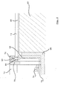
- the conductor 64 is in the plastic material of the junction box 16 embedded.
- the junction box is in any way, be it by a spreading device or, as shown here, by a fastening material 68 - connected to the masonry 62.
- the conductor 64 has at the bottom 72 of the junction box 16 a Turn on. There is a socket 74 is formed, the the connection of a plug that is connected to the home automation unit connected is. This socket is basically off too Fig. 5 can be seen.
- the insulation displacement terminal 54 with a Cover cap 76 covered to prevent accidental touching to prevent protruding cutting terminal.
- FIG. 4 From Fig. 4 it can be seen in which way two adjacent Junction boxes 10 can be connected to each other.
- the insulation displacement terminals 54 are in this solution with a connecting bridge 78 bridged, which at the same time also the insulation after ensures at the front.
- each installation box 16 has four terminals 80, the insulation displacement terminals 54 each wear.
- connection devices 80 are each color-coded, and for the electrician is It's easy to recognize that related pages the junction boxes are connected to each other in the same way should.
- each junction box for example, with be indicated by an arrow 82 which faces upward.
- a home automation unit 84 introduced into the installation box 16 according to the invention can be.
- a plug 86 is in the socket 74, when the home automation unit 84 is installed. This is the Voltage tap for the home automation unit guaranteed.
- the home automation unit 84 can be designed as a switch actuator be; which is controlled via the control lines and Light terminals 88 turns on according to the operator's specification and off.
- any other domestic engineering units such as sockets
- a so-called Western bush which may be bipolar, training.
- Such a socket can either combined with a socket insert or separately be executed centrally in the front.
- a socket 74 for the voltage tap can be realized. Again, a preferred one slightly greater distance 90 between the signal lines provided on the one hand and the power lines on the other. By a partition wall 92 also ensures a mechanical blockage, which prevents the connector concerned from being wrong is inserted.
- an installation box 16 is formed can be, if a masonry-free wall, so a Cavity wall is realized.
- the inventive Ribbon cable at the back of the installation box 16 or pinch, and the socket 74 is on provided in the same place as in the above bebraerien Embodiments are provided.
- FIG. 10 A further modified installation box 16 is shown in FIG. 10 seen.
- This is a surface-mounted box. This can is basically in two parts, with the lower part 98 over Fixing screws 100 can be connected to the masonry 62. Again, a ribbon cable is used, the s.den known terminals 80 is clamped and the Socket 74 feeds. By placing the upper part 102 At the same time, a seal 104 seals the installation box 16 guaranteed.
- the upper part 102 is formed virtually flat cylindrical and can accordingly be free of printed conductors.
- FIG. 11 shows a further variant of the connection. here as well as in the other figures reference numerals are shown with the same parts.
- the socket 74 fits mechanically exactly to the plug 86. It lies on the floor 72nd the installation box and is connected to the conductor 64.
- the plug 86 is in contrast suitable in any other Way formed, wherein the illustrated embodiment shows a connection with a cutting clamp, corresponding to that, as provided outside the installation boxes 16 is.
Landscapes
- Engineering & Computer Science (AREA)
- Architecture (AREA)
- Civil Engineering (AREA)
- Structural Engineering (AREA)
- Connections Arranged To Contact A Plurality Of Conductors (AREA)
- Details Of Connecting Devices For Male And Female Coupling (AREA)
Applications Claiming Priority (3)
| Application Number | Priority Date | Filing Date | Title |
|---|---|---|---|
| DE102004021679 | 2004-04-29 | ||
| DE202004020605U DE202004020605U1 (de) | 2004-04-29 | 2004-04-29 | Elektroinstallationsanordnung |
| DE200410021679 DE102004021679B4 (de) | 2004-04-29 | 2004-04-29 | Elektroinstallationsanordnung |
Publications (1)
| Publication Number | Publication Date |
|---|---|
| EP1592102A1 true EP1592102A1 (fr) | 2005-11-02 |
Family
ID=34983294
Family Applications (1)
| Application Number | Title | Priority Date | Filing Date |
|---|---|---|---|
| EP05009505A Withdrawn EP1592102A1 (fr) | 2004-04-29 | 2005-04-29 | Dispositif d'installation électrique |
Country Status (2)
| Country | Link |
|---|---|
| EP (1) | EP1592102A1 (fr) |
| DE (1) | DE202004020605U1 (fr) |
Families Citing this family (1)
| Publication number | Priority date | Publication date | Assignee | Title |
|---|---|---|---|---|
| DE102014004325A1 (de) * | 2014-03-26 | 2015-10-01 | Abb Ag | Unterputzeinsatz eines elektrischen Installationsgerätes |
Citations (10)
| Publication number | Priority date | Publication date | Assignee | Title |
|---|---|---|---|---|
| US3253085A (en) * | 1963-08-15 | 1966-05-24 | Arnold S Stern | Electrical conductor with adhesive backing |
| GB2212343A (en) * | 1987-11-12 | 1989-07-19 | Peter Elliott | Electrical junction |
| EP0419031A1 (fr) * | 1989-08-28 | 1991-03-27 | The Whitaker Corporation | Connecteur électrique à prises |
| US5064386A (en) * | 1990-11-27 | 1991-11-12 | Amp Incorporated | Convenience electrical outlet assembly |
| DE4011711A1 (de) * | 1990-04-11 | 1991-11-14 | Walter Grabowski | Installationssystem |
| CH679193A5 (en) * | 1989-07-28 | 1991-12-31 | Bernard Saugy | Combined network and information cable junction box - has pairs of spaced terminals for cable voltage supply and information transmission conductors |
| US5097099A (en) * | 1991-01-09 | 1992-03-17 | Amp Incorporated | Hybrid branch cable and shield |
| EP0665608A2 (fr) * | 1994-01-31 | 1995-08-02 | Däwyler AG Kabel und Systeme | Système de câblage électrique |
| US20020185296A1 (en) * | 2000-01-07 | 2002-12-12 | Schultz James Douglas | Prewired electrical apparatus having quick connect components |
| DE10242448A1 (de) * | 2002-09-11 | 2004-03-25 | Frank Prochiner | Anschlußelement eines Elektroinstallationssystems |
-
2004
- 2004-04-29 DE DE202004020605U patent/DE202004020605U1/de not_active Expired - Lifetime
-
2005
- 2005-04-29 EP EP05009505A patent/EP1592102A1/fr not_active Withdrawn
Patent Citations (10)
| Publication number | Priority date | Publication date | Assignee | Title |
|---|---|---|---|---|
| US3253085A (en) * | 1963-08-15 | 1966-05-24 | Arnold S Stern | Electrical conductor with adhesive backing |
| GB2212343A (en) * | 1987-11-12 | 1989-07-19 | Peter Elliott | Electrical junction |
| CH679193A5 (en) * | 1989-07-28 | 1991-12-31 | Bernard Saugy | Combined network and information cable junction box - has pairs of spaced terminals for cable voltage supply and information transmission conductors |
| EP0419031A1 (fr) * | 1989-08-28 | 1991-03-27 | The Whitaker Corporation | Connecteur électrique à prises |
| DE4011711A1 (de) * | 1990-04-11 | 1991-11-14 | Walter Grabowski | Installationssystem |
| US5064386A (en) * | 1990-11-27 | 1991-11-12 | Amp Incorporated | Convenience electrical outlet assembly |
| US5097099A (en) * | 1991-01-09 | 1992-03-17 | Amp Incorporated | Hybrid branch cable and shield |
| EP0665608A2 (fr) * | 1994-01-31 | 1995-08-02 | Däwyler AG Kabel und Systeme | Système de câblage électrique |
| US20020185296A1 (en) * | 2000-01-07 | 2002-12-12 | Schultz James Douglas | Prewired electrical apparatus having quick connect components |
| DE10242448A1 (de) * | 2002-09-11 | 2004-03-25 | Frank Prochiner | Anschlußelement eines Elektroinstallationssystems |
Also Published As
| Publication number | Publication date |
|---|---|
| DE202004020605U1 (de) | 2005-09-08 |
Similar Documents
| Publication | Publication Date | Title |
|---|---|---|
| DE2911065C2 (fr) | ||
| EP3338149B1 (fr) | Méthode d'exploitation d'un distributeur de courant et distributeur de courant | |
| EP0798819B1 (fr) | Dispositif pour la fixation détachable d'un ou de plusieurs appareils à un ou plusieurs endroits et pour leur connexion électrique | |
| DE4019465A1 (de) | Anschlusseinrichtung fuer die hausleittechnik | |
| EP1258957A1 (fr) | Ensemble d'interrupteurs | |
| EP3186862B1 (fr) | Module d'automatisation pour la domotique | |
| EP0510123B1 (fr) | Systeme de cablage electrique domestique | |
| DE102014205744A1 (de) | Steuergerät für ein Fahrzeugheizgerät | |
| DE29505272U1 (de) | Sensor-Aktor-Verteiler | |
| DE4412673C2 (de) | Elektrisches Installationssystem | |
| DE102004021679B4 (de) | Elektroinstallationsanordnung | |
| DE4404036A1 (de) | Mehrfachsteckdosensystem | |
| DE9315486U1 (de) | Energieversorgungsnetz mit steckbarer Verteilereinrichtung | |
| DE202008004766U1 (de) | Codierbare Motoranschlusssteckkupplung | |
| DE202004020605U1 (de) | Elektroinstallationsanordnung | |
| EP0975079A2 (fr) | Distributeur d'installation électrique | |
| EP2043118B1 (fr) | Appareil d'installation électrique/électronique | |
| EP3827483B1 (fr) | Dispositif de distribution et système d'acheminement et de distribution de l'énergie électrique et de fourniture d'une connexion de communication communiquant des données | |
| EP1665474A1 (fr) | Systeme barre omnibus | |
| WO2009010111A1 (fr) | Distributeur de courant | |
| AT386495B (de) | Anordnung zur stromversorgung | |
| AT386704B (de) | Anordnung zur stromversorgung | |
| EP2551969B1 (fr) | Boîte de jonction pour conduites électriques et système de répartition électrique avec des boîtes de jonction de ce type | |
| DE4211602C1 (fr) | ||
| DE202015102508U1 (de) | Installationsdose sowie Installationssystem |
Legal Events
| Date | Code | Title | Description |
|---|---|---|---|
| PUAI | Public reference made under article 153(3) epc to a published international application that has entered the european phase |
Free format text: ORIGINAL CODE: 0009012 |
|
| AK | Designated contracting states |
Kind code of ref document: A1 Designated state(s): AT BE BG CH CY CZ DE DK EE ES FI FR GB GR HU IE IS IT LI LT LU MC NL PL PT RO SE SI SK TR |
|
| AX | Request for extension of the european patent |
Extension state: AL BA HR LV MK YU |
|
| AKX | Designation fees paid |
Designated state(s): AT BE BG CH CY CZ DE DK EE ES FI FR GB GR HU IE IS IT LI LT LU MC NL PL PT RO SE SI SK TR |
|
| STAA | Information on the status of an ep patent application or granted ep patent |
Free format text: STATUS: THE APPLICATION IS DEEMED TO BE WITHDRAWN |
|
| 18D | Application deemed to be withdrawn |
Effective date: 20060530 |