EP1591786B1 - Appareil pour déterminer des courves de solidification par cristallisation des masses de chocolat ou des masses graisseuses similaires - Google Patents
Appareil pour déterminer des courves de solidification par cristallisation des masses de chocolat ou des masses graisseuses similaires Download PDFInfo
- Publication number
- EP1591786B1 EP1591786B1 EP20050008438 EP05008438A EP1591786B1 EP 1591786 B1 EP1591786 B1 EP 1591786B1 EP 20050008438 EP20050008438 EP 20050008438 EP 05008438 A EP05008438 A EP 05008438A EP 1591786 B1 EP1591786 B1 EP 1591786B1
- Authority
- EP
- European Patent Office
- Prior art keywords
- chamber
- piston
- housing
- measurement chamber
- section
- Prior art date
- Legal status (The legal status is an assumption and is not a legal conclusion. Google has not performed a legal analysis and makes no representation as to the accuracy of the status listed.)
- Expired - Lifetime
Links
Images



Classifications
-
- G—PHYSICS
- G01—MEASURING; TESTING
- G01N—INVESTIGATING OR ANALYSING MATERIALS BY DETERMINING THEIR CHEMICAL OR PHYSICAL PROPERTIES
- G01N25/00—Investigating or analyzing materials by the use of thermal means
- G01N25/02—Investigating or analyzing materials by the use of thermal means by investigating changes of state or changes of phase; by investigating sintering
- G01N25/04—Investigating or analyzing materials by the use of thermal means by investigating changes of state or changes of phase; by investigating sintering of melting point; of freezing point; of softening point
-
- G—PHYSICS
- G01—MEASURING; TESTING
- G01N—INVESTIGATING OR ANALYSING MATERIALS BY DETERMINING THEIR CHEMICAL OR PHYSICAL PROPERTIES
- G01N33/00—Investigating or analysing materials by specific methods not covered by groups G01N1/00 - G01N31/00
- G01N33/02—Food
-
- Y—GENERAL TAGGING OF NEW TECHNOLOGICAL DEVELOPMENTS; GENERAL TAGGING OF CROSS-SECTIONAL TECHNOLOGIES SPANNING OVER SEVERAL SECTIONS OF THE IPC; TECHNICAL SUBJECTS COVERED BY FORMER USPC CROSS-REFERENCE ART COLLECTIONS [XRACs] AND DIGESTS
- Y10—TECHNICAL SUBJECTS COVERED BY FORMER USPC
- Y10T—TECHNICAL SUBJECTS COVERED BY FORMER US CLASSIFICATION
- Y10T137/00—Fluid handling
- Y10T137/8593—Systems
-
- Y—GENERAL TAGGING OF NEW TECHNOLOGICAL DEVELOPMENTS; GENERAL TAGGING OF CROSS-SECTIONAL TECHNOLOGIES SPANNING OVER SEVERAL SECTIONS OF THE IPC; TECHNICAL SUBJECTS COVERED BY FORMER USPC CROSS-REFERENCE ART COLLECTIONS [XRACs] AND DIGESTS
- Y10—TECHNICAL SUBJECTS COVERED BY FORMER USPC
- Y10T—TECHNICAL SUBJECTS COVERED BY FORMER US CLASSIFICATION
- Y10T137/00—Fluid handling
- Y10T137/8593—Systems
- Y10T137/85978—With pump
Definitions
- the invention relates to a device for detecting crystallization solidification curves of chocolate and similar fat masses, comprising a housing, a discharge point for liquid chocolate formed therein, with a connected to the sampling point and a cooled wall measuring chamber in which the liquid chocolate mass for solidification is brought, with a movable piston provided in the housing, with a temperature sensor provided in the housing and with a device for removing the solidified sample from the measuring chamber.
- a device for detecting crystallization solidification curves of chocolate and similar fat masses comprising a housing, a discharge point for liquid chocolate formed therein, with a connected to the sampling point and a cooled wall measuring chamber in which the liquid chocolate mass for solidification is brought, with a movable piston provided in the housing, with a temperature sensor provided in the housing and with a device for removing the solidified sample from the measuring chamber.
- Such devices are commonly referred to in the industry as tempermeter. They serve to determine the tempering of a liquid chocolate or a similar fat mass. Such temper meters are often operated automatically
- a temperature sensor approximately in the center of this sample measures the course of the temperature and forwards it to an evaluation device, with the aid of which the temperature profile over time is recorded, in particular represented.
- the course of this temperature curve gives the expert information about the Temperiergrad or Temperierindex and thus about the quality of the pre-crystallized liquid chocolate.
- Such tempering can also be used in the context of a control or regulating device to make the necessary adjustments in the present over- or Untertemperleiter to the setting conditions, for example, a tempering, so ultimately matched to the desired work result ideally tempered chocolate and can be processed.
- a device of the type described above is known from DE 37 14 951 C1 known. It is provided a measuring chamber, which is enclosed by a cooled wall. The measuring chamber is connected to a discharge point for liquid pre-crystallized chocolate, for example to a pipe section from which the liquid chocolate is taken for the sample. The measuring chamber partially protrudes into the flow cross-section of the pipeline.
- the measuring chamber itself has a cylindrical cross-section and is thus adapted to a movable in the measuring chamber arranged cylindrical piston.
- the piston carries a temperature sensor, which projects beyond the front wall of the piston and protrudes in the retracted position of the piston in the measuring chamber, where it tracks and absorbs the temperature of the solidifying sample.
- the measuring chamber is thus formed by a piston / cylinder unit, which is arranged dipping with its open end face in the chocolate mass to be detected.
- a drive for the stroke of the piston which is dimensioned approximately to the length of the measuring chamber.
- a device for removing the solidified sample from the piston and the temperature sensor is provided.
- This device consists of a mechanical comminution device, in particular a milling and cutting device, whose axis is arranged in alignment with the axis of the measuring chamber.
- the milling or cutting device has a shaft driven by a motor and a milling head, which protrudes into the flow cross section of the measuring point from the outside and partially blocks the flow cross section. The protruding shaft must be sealed.
- the known device is operated as follows. By a return stroke of the piston in the measuring chamber liquid chocolate mass is sucked from the sampling point and transferred into the measuring chamber. Due to the influence of the cooled wall of the measuring chamber, a solidification process of the liquid sample takes place until the entire material of the sample has solidified. To be able to aspirate the next sample of liquid chocolate into the measuring chamber, first the solidified sample has to be removed from the measuring chamber. This is done by the mechanical shredding device with which the solidified sample is milled. The resulting solid particles are added to the milling process across the liquid chocolate mass flowing through the sampling point, removed and melted. This comminution and dissolution process of the solidified sample takes several minutes.
- the measuring chamber is blocked, ie no new sample can be transferred into the measuring chamber. Rather, the complete must Wait for the comminution and dissolution process of the solidified sample before a new sample can be drawn.
- the time taken to examine a sample is thus relatively long, so that in this way only samples can be taken at appropriate time intervals. Often, however, a control system requires a faster time sequence of different samples.
- the known device has the further disadvantage that the mechanical shredding device requires its own drive, which is provided outside the removal point and has rotationally driven elements.
- the implementation of the drive shaft through the wall of the sampling point for example in the form of a pipe or a pipe section, requires a seal. This seal is a wearing part and must be changed regularly to prevent chocolate leakage.
- Another disadvantage is that an exact control of the drive for the piston in the measuring chamber and for the mechanical crusher is required.
- the forward stroke of the piston with the solidified sample must not be faster than the shredding unit can mill the solidified sample.
- the invention has for its object to provide a device of the type described above, with the particular automatically successive samples can be drawn and recorded in relatively shorter time intervals.
- the invention is based on the idea to provide a separate reflow chamber for melting the solidified sample.
- the melting chamber and the measuring chamber are thus provided locally separated from each other, preferably at a distance which corresponds at least to the diameter of the flow cross-section at the removal point. Only the arrangement of the melting chamber and the measuring chamber is coordinated so that their axes are aligned or parallel to each other. As a rule, both the measuring chamber and the melting chamber have a circular or at least partially cylindrical cross-section.
- a first embodiment which is characterized by aligned axes of the measuring chamber and the reflow chamber of the linear reciprocating stroke of the piston is extended compared to the stroke of the piston of the known device, so that a solidified sample from the measuring chamber are transferred to the Aufschmelzhunt can and the flow cross-section of the sampling point is immediately released during the return stroke of the piston into the measuring chamber, so that during this return stroke, without the solidified sample in the melting chamber is already melted, a subsequent sample of liquid chocolate mass can be sucked into the measuring chamber.
- the preceding solidified sample is melted in the reflow chamber. This leads to a considerable reduction in the time cycle with which samples can be examined in succession, because the solidification process of the sample in the measuring chamber and the melting process in the melting chamber overlap in time.
- a means for holding the solidified sample is provided in or on the reflow chamber, which takes effect during or during the insertion of the solidified sample into the reflow chamber and holds the solidified sample in the reflow chamber, while the piston from the solidified sample at the beginning of its return stroke solves.
- the piston is designed as a rotary piston and has at least three chambers which, depending on the rotational position of the rotary piston, alternately form the measuring chamber, the melting chamber and a chamber connected to the removal point.
- the rotary piston is clocked rotatably driven in a housing, wherein the chambers are formed on the rotary piston as a part-cylindrical longitudinal grooves. In the Takeover position connects a chamber to the sampling point. In a second position, the chamber, together with the liquid chocolate mass removed from the withdrawal point, is rotated into a position in which the chamber performs the function of the measuring chamber.
- a temperature sensor is mounted in the housing and retractable into the chamber in this position and extendable.
- a cooling device is provided in this area, with which the chocolate mass is solidified.
- the solidification curve is recorded.
- the melting chamber is provided or formed, in which the sample is remelted via a heating device provided in the housing.
- the chamber of the rotary piston continues to rotate in this position.
- the chamber of the rotary piston continues to turn and is connected to the removal point, so that the sample melted again in the melting chamber is again discharged into the flow of the chocolate mass.
- the new device avoids by the separate melting chamber and all the disadvantages associated with a mechanical comminution of the solidified sample.
- the return of solid particles, as they arise during the milling process is avoided in the flow path of the liquid pre-crystallized chocolate.
- the melting process can be carried out gently and evenly. There are no large differences in temperature must be applied so that the chocolate mass is not damaged. This is possible because for the melting process in principle, the time or about the time is available, which also requires the solidification process of the subsequent sample.
- the device can use the flow cross-section in a pipe section as a sampling point.
- the device is thus arranged in or on this pipe section.
- Such a pipe section can be installed in a simple manner in each pipeline, is passed through the liquid chocolate mass, for example from a tempering machine to a processing machine.
- the measuring chamber on the one hand and the melting chamber on the other hand to arrange approximately symmetrically to the axis of the pipe section opposite.
- the common axis of the measuring chamber and the melting chamber are perpendicular to the axis of the pipe section. Since the melting chamber has no driven moving elements, advantageously also eliminates a sealing of the drive shaft required in the prior art for the mechanical crusher. The elimination of the seal, the device is much more reliable and requires reduced maintenance.
- the measuring chamber and / or the melting chamber are preferably approximately cylindrical, ie they have a circular cross-section. It is understood that the cross-section or diameter of the melting chamber may not be smaller than the diameter of the measuring chamber. However, it makes sense that both the measuring chamber and the melting chamber are located at least substantially outside the flow cross section of the removal point, so that this flow cross section is not significantly impaired by the arrangement of the two chambers. However, it is necessary to ensure that the solidified sample ejected from the measuring chamber and to be inserted into the melting chamber does not prematurely detach from the piston and then be entrained by the chocolate flowing in the flow cross-section of the extraction point. This could lead to disruption of the operation.
- a guide cage for the transfer of the solidified sample from the measuring chamber into the melting chamber is provided in the flow cross section of the removal point.
- This guide cage guides and guides the solidified sample on its way out of the measuring chamber into the melting chamber. Even if the solidified sample is released prematurely from the surface of the piston, it prevents entrainment by the liquid chocolate, which flows continuously through the extraction point. This ensures that the solidified sample is safely and reproducibly transferred into the melting chamber and then subsequently melted there.
- the guide cage is expediently designed as a perforated sleeve section whose axis is arranged in alignment with the common axis of the measuring chamber and the melting chamber.
- the sleeve section should have large openings in order to affect the flow through the extraction point with liquid chocolate as little as possible.
- a cage-like construction of wire sections can be used, which fulfills the described leadership and leadership function.
- the chambers provided on the rotary piston change their functions, depending on the relative position in the housing. This has the advantage that a guide cage is unnecessary. The cross section of the pipeline remains completely free in every standstill position of the rotary piston at the sampling point and is therefore not partially blocked.
- the measuring chamber is provided with a cooling device and the melting chamber with a heater.
- the cooling can be done by cooling water or thermoelectric, for example, by a Peltier element.
- the wall of the measuring chamber can be double-walled and connected to a circuit for cooling water.
- the temperature of the cooling water can be kept constant over time, d. H.
- the drive of the piston is sufficient to release the solidified sample from the inner wall of the measuring chamber.
- the corresponding advantage of a temporally constant temperature also results for the melting chamber or the connection of a double wall to constant temperature hot water. This advantageously eliminates the periodic heating or cooling of metallic walls.
- the solidified sample introduced into the reflow chamber must be held in the reflow chamber during the return stroke of the piston.
- the device for holding the solidified sample during the return stroke of the piston has a receiving sleeve, are provided in or on the retaining elements for the inserted solidified sample. These retainers must reliably hold the solidified specimen and allow the piston to disengage from the rear face of the solidified specimen as the return stroke of the piston begins.
- a ball valve which is associated with the receiving sleeve, curved blades, barbs or the like are used, which fix the inserted solidified sample relative to the receiving sleeve.
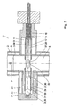
- Fig. 1 shows a preferred embodiment of the device 1.
- the device 1 has a housing 2, which is designed as a pipe section 3.
- the housing 2 may also have a different shape.
- a pipe section 3 is preferred because it allows the device to be installed in pipes in a very simple manner via corresponding flange connections on the pipe section.
- the housing 2 or the pipe section 3 has an axis 4.
- a flow cross-section 5 is formed, which is circular here and flows through the liquid chocolate mass 6 in the direction of the arrow 7 from bottom to top. As a rule, it is a continuous flow of the chocolate mass 6, driven by a pump, not shown.
- the housing 2 of Device 1 is usually formed double-walled.
- a space 8 formed in this way is connected to a circuit with tempered water, which acts as a protective heater and prevents the liquid chocolate mass from undergoing a change in temperature during its flow over the length of the pipe section 3.
- a measuring chamber 9 is arranged, which is also double-walled.
- the formed gap is connected to a circuit 10 for cooling water.
- the circuit 10 of the cooling water is operated at an adjustable but constant temperature. In this way, a cooling device 11 is provided for the measuring chamber 9.
- a hollow cylinder 12 is formed, which has connection to the flow cross-section 5 of the housing 2.
- the cylinder 12 has an axis 13 which is arranged perpendicular to the axis 4 of the flow cross-section 5.
- a piston 14 is provided, which is via a drive, not shown, in the direction of the axis 13 and thus of the double arrow 15, ie with forward and return stroke, movable.
- the piston 14 carries a temperature sensor 16, which is arranged centrally in the piston 14 and whose front end 17 protrudes freely.
- the piston 14 has a piston rod 18 which on the one hand serves to drive the piston 16 and through which, on the other hand, leads 19 of the temperature sensor 16 are led outwards to an evaluation and recording device, not shown.
- the measuring space 20 is located approximately where according to FIG Fig. 1 the movable piston 14 is shown. When the piston 14 comes to its rear dead center, as in Fig. 2 is shown, the measuring space 20 is fully visible.
- a reflow chamber 21 is arranged on the opposite side of the measuring chamber 9 of the housing 2 and the pipe section 3. Also, the melting chamber 21 is double-walled. The formed gap is connected to a circuit 22 for hot water. In this way, a heater 23 is formed. Other embodiments of the heater 23 are conceivable. The heater 23 could also be electrically formed. The circuit 22 is also operated with water, here with hot water. The temperature is adjustable and can over the Trial period remain constant. The selected temperature must be sufficient to be able to melt a solidified sample of chocolate mass. On the other hand, the temperature must be chosen to be sufficiently low so that the properties of the chocolate mass 6 flowing through the flow cross-section 5 are not adversely affected. In the interior of the melting chamber 21, a melting space 24 is formed.
- the melting space 24, like the measuring space 20, may have a circular cross-section. It expediently has a comparatively slightly larger diameter than the measuring space 20 or an intermediate guide cage 32, so that a solidified sample can be transferred from the measuring space into the melting space. Taking into account that a chocolate mass shrinks on solidification, so the measuring space 20, the guide cage 32 and a receiving sleeve 26 in the melting chamber 24, for example in the form of a continuous pipe section, matching internal diameter.
- the melting chamber 21 or the melting space 24 have an axis 25 which is arranged in alignment with the axis 13 of the measuring space 20.
- the receiving sleeve 26 is mounted stationary. In association with the stationary receiving sleeve 26 curved blades 27 are arranged.
- Barb-like elements may also be provided.
- the receiving sleeve 26 may be provided with apertures, not shown.
- the outer diameter of the receiving sleeve 26 is smaller than the inner diameter of the melting space 24 in order to create an overflow channel 29 for the return flow of melted chocolate mass into the flow cross-section 5.
- the blades 27, barbs and / or the ball valve 28 form retaining elements 30.
- a device 31 for holding or retaining an inserted solidified sample 38 in the melting chamber 21 is thus created.
- the elements of the device 31 for holding a solidified sample are to be understood by way of example. The person skilled in the art also offers other possibilities of realization.
- the guide cage 32 has a sleeve portion 33 which is provided with large-sized apertures 34.
- the guide cage 32 serves to guide and guide a solidified sample during its transfer from the measuring space 20 into the melting space 24 and thus to prevent floating in the flow cross-section 5 in the direction of the arrow 7.
- the guide cage 32 could also be a lightweight wire construction be educated. He is usually connected to the receiving sleeve 26 and supported on this. It could also be designed in one piece with the receiving sleeve 26.
- the guide cage 32 or the sleeve section 33 has an axis 35. The axis 35 is aligned with the axes 13 and 25, so that in this way a common axis is formed.
- the stroke of the piston 14 is dimensioned such that it can be moved to the end of the guide cage 32 or to the beginning of the receiving sleeve 26 of the reflow chamber 21 to a solidified sample from the measuring chamber 20 of the measuring chamber 9 in the receiving sleeve 26 of the reflow chamber 21 convict.
- the piston 14 with its piston rod 18 and the associated drive essentially form the moving parts of the device 1.
- the device 1 is preferably operated continuously, i. H. Samples of the chocolate mass 6 are removed from the flow cross-section 5 at fixed intervals, solidified and remelted. Such a cycle is as follows:
- a removal point 37 is formed, which is always flowed through by liquid chocolate mass 6.
- This removal point 37 may be provided in the region of the large openings 34 of the guide cage 32 or else in the measuring chamber 20 of the measuring chamber 9 facing wall portion of the housing 2, if the guide cage 32 on the wall of the pipe section 3 is not supported on the measuring space 20, So a little shorter.
- the measuring chamber 20 must always be connected to the flow cross-section 5, so that upon a return stroke of the piston 14 in the transition from the position of Fig. 1 in the position according to Fig. 2 a suction stroke of the measuring chamber 9 is realized, through which the measuring chamber 20 is filled with fresh liquid chocolate mass 6, which is then brought to solidification by the action of the cooling device 11.
- the solidified sample 38 ie a cylindrical plug of solid chocolate mass, forms in the measuring space 20.
- This solidification process is detected by the temperature sensor 16 whose front end 17 is arranged at a representative point of the measuring space 20 or the solidified sample 38.
- the temperature profile of the sample 38 is recorded and evaluated in a known manner.
- the drive of the piston 14 is set in motion so that it performs its forward stroke.
- These processes are at the transition from the position according to Fig. 2 in the position according to Fig. 3 clarified.
- the peripheral surface of the sample 38 separates from the inner wall of the measuring chamber 20, while the end wall of the sample 38 facing the piston 14 adheres to the piston 14.
- the solidified sample 38 first passes into the region of the guide cage 32, through the cavity of which the sample 38 is guided and guided. The guide cage 32 prevents the sample 38 from coming off the end face of the piston 14.
- the sample 38 would come loose in the region of the flow cross-section 5, it could be taken along by the chocolate mass 6 flowing according to arrow 7 and, to that extent, not reach the melting chamber 21. This must be prevented, either by the arrangement of a guide cage 32 or by corresponding enlargement of the contact surface in the end region between the piston 14 and sample 38.
- the guide cage 32 with its large openings 34 does not disturb the flow in the flow cross-section 5 appreciably, so that his arrangement makes sense.
- the guide cage 32 is matched to the receiving sleeve 26 of the reflow chamber 21 and dimensioned so that upon continued forward stroke of the piston 14, the solidified sample 38 enters the receiving sleeve 26 ( Fig. 3 ).
- the molten chocolate mass present in the receiving sleeve 26 is opened by opening the ball valve 38 (see arrow illustration in FIG Fig. 3 ) are moved into the overflow channel 29 and from there into the flow cross section 5.
- the retaining elements 30 or the device 31 for holding the solidified sample 38 in the receiving sleeve 26 or the melting chamber 21 come into operation. It can be done by closing the ball valve 28 after reaching the front dead center of the stroke of the piston 14 is already a certain holding the solidified sample 38 when the piston 14 begins its return stroke. This effect is particularly great when the receiving sleeve 26 has no openings on its cylindrical wall.
- the curved blades 27 or other barb-shaped elements in the region of the receiving sleeve 26 may favor the retention of the solidified sample inserted into the receiving sleeve 26 and thus make it possible to detach the end face of the piston 14 from the solidified sample 38 do.
- the solidified sample 38 is thus in the melting chamber and remains there, while the piston 14 passes through its return stroke. As soon as he is in the position Fig. 1 As this measurement and recording of the solidification curve takes place, the solid sample 38 of the past cycle is melted in the reflow chamber 21, ie in the molten state Condition convicted.
- the molten-heated chocolate mass of the preceding sample is then displaced during the transfer and returned to the flow cross-section 5. It can thus be seen that the solidification of a subsequent sample and the melting of the preceding sample can be carried out in a time-overlapping manner. This coverage can be used in whole or in part. In any case, the cycle time in such an automatic monitoring of a flowing chocolate mass is considerably shorter.
- Fig. 4 details of the means 31 for holding a solidified and transferred to the receiving sleeve 26 sample 38, but without showing the sample itself.
- two blades 27 are provided in the relative position shown, which, as well as Fig. 1 recognizable, have bent resilient ends 39.
- the other ends of the blades 27 may be formed sharpened so that the blades 27 when inserting a solidified sample 38 cut into it.
- the blades 27 are held by welds 40 on the inner circumference of the receiving sleeve 26.
- the bent blades 27 assume a stretched shape and thus wave as retaining elements 30. It is understood that there are other possibilities for the realization of the retaining elements 30.
- a plurality of short thin blade-like ribs, starting from the inner periphery of the receiving sleeve 26 may be provided radially extending and axially continuous, which cut 38 when inserted into the periphery of the solidified sample.
- a second embodiment of the device 1 is illustrated.
- This device 1 has a housing 2, which has a pipe section 3 which is connected to a conveying line for chocolate mass 6, so that the flow cross-section 5 in the housing 2 of chocolate mass perpendicular to the plane of the Fig. 5 is flowed through.
- the pipe section 3 has the axis 4.
- the piston of the device 1 is here designed as a rotary piston 41, whose axis 13 is aligned and spaced from the axis 4 of the flow cross-section 5 is arranged so that the flow cross-section 5 is cut by the rotary piston 41.
- the rotary piston 41 is cyclically rotated according to arrow 42 in the three positions.
- the rotary piston 41 has at least three chambers 43 in the same pitch.
- the chambers 43 are formed identically and consist of a section of a cylinder, which here in each case complements the flow cross-section 5.
- the three chambers 43 change depending on the rotational position and take the function of a sampling chamber, a measuring chamber 9 and a melting chamber 21 a.
- the temperature sensor 16 can be moved into the measuring chamber 9 or moved out of it in the housing 2 of the device 1.
- the housing 2 has cooling channels (not shown), through which a cooling medium flows, so that the liquid chocolate mass can be solidified in the area of the measuring chamber 9. Accordingly, 2 channels are provided in the housing 2 in the region of the melting chamber, which are connected to a heating circuit (not shown).
- Fig. 5 shows the position of the parts after half a turn, ie in an intermediate position. Again, the temperature sensor 16 is still outside the measuring chamber. According to Fig. 7 Finally, the rotation is shown, which is achieved after a rotation by an integral division with the chambers 43.
- Upper chamber 43 has taken liquid chocolate mass from the flow cross section 5 and transferred into an area in which the chamber 43 assumes the function of the measuring chamber 9. The temperature sensor 16 is retracted into the still liquid chocolate mass in the region of the measuring chamber 9 ( Fig.
- Fig. 8 lets recognize the structure of the device 1 in a vertical section. It is shown here only the structure of the housing and the arrangement of the rotary piston 41 in the housing 2. For clarity, the drive for the rotary piston 41 is omitted, as are the channels for a cooling and a heating medium.
Landscapes
- Chemical & Material Sciences (AREA)
- Health & Medical Sciences (AREA)
- Life Sciences & Earth Sciences (AREA)
- General Health & Medical Sciences (AREA)
- Analytical Chemistry (AREA)
- Biochemistry (AREA)
- Physics & Mathematics (AREA)
- General Physics & Mathematics (AREA)
- Immunology (AREA)
- Pathology (AREA)
- Engineering & Computer Science (AREA)
- Food Science & Technology (AREA)
- Medicinal Chemistry (AREA)
- Confectionery (AREA)
Claims (10)
- Appareil pour déterminer des courbes de solidification par cristallisation de masses de chocolat et de masses de graisse similaires, avec
un boîtier (2),
un emplacement de prélèvement (37) de chocolat liquide (6) qui est formé dans le boîtier,
une chambre de mesure (9) raccordée à l'emplacement de prélèvement (37) et présentant une paroi refroidie, dans laquelle chambre la masse de chocolat liquide (6) est amenée à se solidifier,
un piston mobile prévu dans le boîtier (2),
une sonde de température (16) prévue dans le boîtier (2), et
un dispositif pour enlever de la chambre de mesure (9) l'échantillon solidifié (38), caractérisé en ce
qu'une chambre de fusion (21) séparée pour l'échantillon solidifié (38) est prévue en relation avec la chambre de mesure (9), et
la course du piston (14, 41) est dimensionnée pour le transfert de l'échantillon solidifié (38) à partir de la chambre de mesure (9) vers la chambre de fusion (21). - Appareil selon la revendication 1, caractérisé en ce que
le piston est réalisé en tant que piston (14) pouvant effectuer un mouvement de va-et-vient linéaire,
la chambre de fusion (21) est disposée en affleurement avec la chambre de mesure (9), et
dans la chambre de fusion (21), il est prévu un dispositif (31) pour le maintien de l'échantillon solidifié (38) pendant la course de retour du piston (14). - Appareil pour déterminer des courbes de solidification par cristallisation de masses de chocolat et de masses de graisse similaires, avec
un boîtier (2),
un emplacement de prélèvement (37) de chocolat liquide (6) qui est formé dans le boîtier,
une chambre de mesure (9) raccordée à l'emplacement de prélèvement (37) et présentant une paroi refroidie, dans laquelle chambre la masse de chocolat liquide (6) est amenée à se solidifier,
un piston mobile prévu dans le boîtier (2),
une sonde de température (16) prévue dans le boîtier (2), et
un dispositif pour enlever de la chambre de mesure (9) l'échantillon solidifié (38), caractérisé en ce
qu'une chambre de fusion (21) séparée pour l'échantillon solidifié (38) est prévue en relation avec la chambre de mesure (9), et
le piston est réalisé en tant que piston rotatif (41) et présente au moins trois chambres (43) qui, en fonction de la position de rotation respective du piston rotatif (41) dans le boîtier (2), forment alternativement la chambre de mesure (9), la chambre de fusion (21) et une chambre raccordée à l'emplacement de prélèvement (37). - Appareil selon la revendication 2 ou 3, caractérisé en ce que l'emplacement de prélèvement (37) est disposé dans un tronçon de conduite tubulaire (3) du boîtier (2), et en ce que la chambre de mesure (9) d'une part et la chambre de fusion (21) d'autre part sont disposées de façon opposée à peu près symétriquement par rapport à l'axe (4) du tronçon de conduite tubulaire (3).
- Appareil selon au moins une des revendications 1 à 4, caractérisé en ce que la chambre de mesure (9) et/ou la chambre de fusion (21) sont réalisées de façon approximativement cylindrique ou partiellement cylindrique, et en ce qu'elles sont disposées au moins pour l'essentiel à l'extérieur de la section transversale d'écoulement (5) de l'emplacement de prélèvement (37) dans le boîtier (2).
- Appareil selon les revendications 1 et 2, caractérisé en ce que, dans la section transversale d'écoulement (5) de l'emplacement de prélèvement (37) dans le boîtier (2), il est prévu une cage de guidage (32), réalisée en particulier en tant que tronçon de manchon (33) percé, pour le transfert de l'échantillon solidifié (38) à partir de la chambre de mesure (9) vers la chambre de fusion (21), cage dont l'axe (35) est disposé en affleurement avec les axes (13, 25) de la chambre de mesure (9) et de la chambre de fusion (21).
- Appareil selon au moins une des revendications 1 à 6, caractérisé en ce qu'il est prévu un dispositif de refroidissement (11) dans la zone de la chambre de mesure (9) et un dispositif de chauffage (23) dans la zone de la chambre de fusion (21).
- Appareil selon les revendications 1 et 2, caractérisé en ce que le dispositif (31) pour le maintien de l'échantillon solidifié (38) pendant la course de retour du piston (14) présente un manchon de réception (26) dans lequel ou sur lequel il est prévu, pour l'échantillon solidifié (38) inséré, des éléments de retenue (30) réalisés en tant que clapet à bille (28), lames courbes (27), ardillons ou similaires.
- Appareil selon la revendication 3, caractérisé en ce que le piston rotatif (41) avec son axe (13) est disposé parallèlement à, et à distance de, l'axe (4) de l'emplacement de prélèvement (37) dans le boîtier.
- Appareil selon les revendications 3 et 9, caractérisé en ce que la sonde de température (16) du piston rotatif (41) prévue dans le boîtier (2) est supportée de façon à pouvoir être introduite dans la chambre de mesure (9) et sortie de la chambre de mesure (9).
Applications Claiming Priority (2)
| Application Number | Priority Date | Filing Date | Title |
|---|---|---|---|
| DE200410021135 DE102004021135B4 (de) | 2004-04-29 | 2004-04-29 | Vorrichtung zum Erfassen von Kristallisations-Erstarrungskurven von Schokolade- und ähnlichen Fettmassen |
| DE102004021135 | 2004-04-29 |
Publications (2)
| Publication Number | Publication Date |
|---|---|
| EP1591786A1 EP1591786A1 (fr) | 2005-11-02 |
| EP1591786B1 true EP1591786B1 (fr) | 2013-09-11 |
Family
ID=34935330
Family Applications (1)
| Application Number | Title | Priority Date | Filing Date |
|---|---|---|---|
| EP20050008438 Expired - Lifetime EP1591786B1 (fr) | 2004-04-29 | 2005-04-19 | Appareil pour déterminer des courves de solidification par cristallisation des masses de chocolat ou des masses graisseuses similaires |
Country Status (4)
| Country | Link |
|---|---|
| US (1) | US7954423B2 (fr) |
| EP (1) | EP1591786B1 (fr) |
| DE (1) | DE102004021135B4 (fr) |
| DK (1) | DK1591786T3 (fr) |
Families Citing this family (11)
| Publication number | Priority date | Publication date | Assignee | Title |
|---|---|---|---|---|
| DE102008016131B4 (de) | 2008-03-28 | 2010-04-08 | Winkler und Dünnebier Süßwarenmaschinen GmbH | Vorrichtung und Verfahren zur Bestimmung des Temperiergrads von fetthaltigen Massen |
| DE102009011969A1 (de) | 2009-03-05 | 2010-09-16 | Sollich Kg | Verfahren und Temperiermaschine zur Regelung der Kristallisation bei dem kontinuierlichen Aufbereiten von zu verarbeitenden fetthaltigen Massen |
| RU2406080C1 (ru) * | 2009-04-28 | 2010-12-10 | Андрей Юрьевич Холин | Устройство для измерения параметров кинетики кристаллизации |
| CN102120256B (zh) * | 2010-12-30 | 2013-03-20 | 中冶连铸技术工程股份有限公司 | 结晶器振动的偏摆位移随时间变化关系的确定方法及装置 |
| DE102011002082A1 (de) | 2011-04-15 | 2012-10-18 | Sollich Kg | Anlernen einer Temperiermaschine für die direkte Einstellbarkeit des Temperiergrads |
| DE202011100655U1 (de) | 2011-05-12 | 2012-08-14 | Mf-Hamburg Maschinen- Und Anlagenbau Gmbh | Vorrichtung zum Erfassen der Temperatur von Schokolade- und ähnlichen Fettmassen |
| AU2015221851B2 (en) * | 2014-02-25 | 2019-05-09 | C.Y. O'connor Erade Village Foundation Inc. | Methods and systems for measuring melting temperatures |
| EP3190410B1 (fr) * | 2016-11-03 | 2018-10-31 | Aasted ApS | Appareil et procédé de test d'échantillons de masse de confiserie |
| DK3398443T3 (da) | 2017-05-02 | 2020-03-02 | Aasted Aps | Apparat til bestemmelse af krystallisationsstørkningskurver for chokolademasse og andre fedtmasser |
| DE102024109624A1 (de) * | 2024-04-05 | 2025-10-09 | Ifm Electronic Gmbh | Verfahren zur Inline Regelung eines Temperprozesses bei der Schokoladenherstellung sowie eine Messanordnung |
| CN119804544B (zh) * | 2025-03-13 | 2025-06-03 | 山东金宜善新材料有限公司 | 一种有机化工产品结晶点测定装置 |
Family Cites Families (21)
| Publication number | Priority date | Publication date | Assignee | Title |
|---|---|---|---|---|
| NL111926C (fr) * | 1956-06-01 | |||
| US3043516A (en) * | 1959-10-01 | 1962-07-10 | Gen Electric | Time summing device for division, multiplication, root taking and interpolation |
| US3143876A (en) * | 1961-01-11 | 1964-08-11 | Sun Oil Co | Apparatus for determining melting point |
| US3154137A (en) * | 1962-10-17 | 1964-10-27 | Greer J W Co | Automatic temper controlling apparatus |
| CH532786A (de) * | 1970-12-30 | 1973-01-15 | Sulzer Ag | Verfahren und Vorrichtung zur Bestimmung des Reinheitsgrades einer Flüssigkeit durch Messung ihres Erstarrungspunktes |
| SU1068763A1 (ru) * | 1982-12-17 | 1984-01-23 | Государственное конструкторское бюро коксохимического машиностроения | Устройство дл отбора проб жидкости |
| US4631967A (en) * | 1985-05-17 | 1986-12-30 | Welker Engineering Company | Automatic insertion device |
| DD241008A1 (de) * | 1985-09-17 | 1986-11-26 | Schokoladenverarbeitungsmaschi | Verfahren zur messtechnischen erfassung des teilkristallinen zustands von schokoladenmassen |
| DE3714951C1 (de) * | 1987-05-06 | 1988-04-14 | Sollich Gmbh & Co Kg | Vorrichtung zum Erfassen von Kristallisations-Erstarrungskurven von Schokolade- und aehnlichen Fettmassen |
| DE4027429A1 (de) * | 1990-08-30 | 1992-03-05 | Sollich Gmbh & Co Kg | Verfahren und vorrichtung zum kontinuierlichen temperieren von zu verarbeitenden kakaobutterhaltigen oder aehnlichen fetthaltigen massen, insbesondere schokolademasse |
| US5162103A (en) * | 1992-01-17 | 1992-11-10 | Auburn International, Inc. | Sample holder compactor for industrial NMR analysis |
| DE4209073C2 (de) * | 1992-03-20 | 1994-01-13 | Deutsches Inst Lebensmitteltec | Verfahren zur Ermittlung von Kristallisationsgüte sowie Kristallanteil vorkristallisierter fluider Fettstoffsysteme oder fetthaltiger Stoffsysteme und Vorrichtung zur Durchführung des Verfahrens |
| DE4316734A1 (de) * | 1992-05-27 | 1993-12-02 | Basf Ag | Probenahmeventil |
| GB2267478A (en) * | 1992-05-29 | 1993-12-08 | Apv Corp Ltd | Apparatus for sampling fluids |
| DE19854204C2 (de) * | 1998-11-24 | 2000-06-15 | Sollich Gmbh & Co Kg | Vorrichtung zum kontinuierlichen Aufbereiten von zu verarbeitenden kakaobutterhaltigen oder ähnlichen fetthaltigen Massen |
| US6164145A (en) * | 1998-12-23 | 2000-12-26 | Jaeger; Ben E. | Liquid sample and method |
| US6481300B1 (en) * | 2000-05-12 | 2002-11-19 | Kent E. Cordry | No purge sampler |
| EP1311822A4 (fr) * | 2000-07-10 | 2008-12-03 | Nanoalert Israel Ltd | Procede et appareil pour determiner la composition de fluides |
| DE10102397A1 (de) * | 2001-01-19 | 2002-07-25 | Zf Batavia Llc | Radialkolbenpumpe |
| US6886420B2 (en) * | 2001-02-01 | 2005-05-03 | Rhe Haendel Engineering Gmbh & Co Kg | Sampling apparatus |
| US6836616B2 (en) * | 2002-02-14 | 2004-12-28 | Valco Cincinnati, Inc. | Molten material application machine |
-
2004
- 2004-04-29 DE DE200410021135 patent/DE102004021135B4/de not_active Expired - Fee Related
-
2005
- 2005-04-19 EP EP20050008438 patent/EP1591786B1/fr not_active Expired - Lifetime
- 2005-04-19 DK DK05008438T patent/DK1591786T3/da active
- 2005-04-27 US US11/115,451 patent/US7954423B2/en active Active
Also Published As
| Publication number | Publication date |
|---|---|
| DE102004021135A1 (de) | 2005-11-24 |
| EP1591786A1 (fr) | 2005-11-02 |
| US7954423B2 (en) | 2011-06-07 |
| DK1591786T3 (da) | 2013-11-25 |
| DE102004021135B4 (de) | 2007-08-02 |
| US20050241491A1 (en) | 2005-11-03 |
Similar Documents
| Publication | Publication Date | Title |
|---|---|---|
| EP1591786B1 (fr) | Appareil pour déterminer des courves de solidification par cristallisation des masses de chocolat ou des masses graisseuses similaires | |
| DE3237999C2 (fr) | ||
| DE102008000262B4 (de) | Vorrichtung und Verfahren zum Filtern von in einem Luftstrom befindlichen Schnittabfällen eines Mikrotoms | |
| DE69610092T2 (de) | Filtervorrichtung | |
| DE69228979T2 (de) | Vorrichtung und Verfahren zur Extraktion mit überkritischen Fluiden | |
| CH667529A5 (de) | Vorrichtung zum dosierten abfuellen von fliessfaehigem fuellgut in behaelter. | |
| DE4433039A1 (de) | Vorrichtung zum Bearbeiten von Dispersionen | |
| DE1944704B2 (de) | Verfahren zum Filtern, insbesondere von durch Wärme weichgemachten thermoplastischen Substanzen, und Vorrichtung zur Durchführung des Verfahrens | |
| DE19637098B4 (de) | Vorrichtung zum Mischen und/oder Verfeinern von Schokolademassen | |
| EP0185958A2 (fr) | Procédé et dispositif pour doser un produit s'écoulant facilement | |
| DE69215361T3 (de) | Blasformverfahren, unter druck stehende flüssigkeitseinspritzvorrichtung und auswurfvorrichtung | |
| DE3714951C1 (de) | Vorrichtung zum Erfassen von Kristallisations-Erstarrungskurven von Schokolade- und aehnlichen Fettmassen | |
| EP2907646B1 (fr) | Dispositif de séparation de particules grossières | |
| DE102004037341C5 (de) | Vorrichtung zum gekühlten Aufbewahren und Abgeben von Proben für eine integrierte Flüssigkeits-Kühleinheit | |
| WO2002035226A1 (fr) | Dispositif de controle destine au controle par ultrasons de barres | |
| EP1623766B1 (fr) | Séparateur centrifugeuse | |
| DE69600340T2 (de) | Vorrichtung zur Behandlung von einer heterogenen Mischung, insbesondere von einer Mischung von Honig und Wachs | |
| DE955089C (de) | Maschinelle Einrichtung zur ununterbrochenen Herstellung von Waschseife | |
| DE202018100632U1 (de) | Prozesssondenanordnung mit Sammelaufsatz und Sammelaufsatz | |
| DE2246672C3 (de) | Probennehmer zur Entnahme von Proben aus einem bei erhöhter Temperatur flüssigen, bei Umgebungstemperatur jedoch festen Material | |
| DE1805163A1 (de) | Zentrifugalgiessvorrichtung und Verfahren zur Herstellung von Zentrifugalguss | |
| DE4411269C2 (de) | Vorrichtung und Verfahren zum Einspeisen einer Probe in einen Probenkanal | |
| EP1810781A1 (fr) | Procédé et dispositif destinés au forage de matériaux de traitement plissés pour des installations d'ombrage | |
| DE3720543C2 (de) | Vorrichtung zum Anfärben von Skeletten tierischer Feten | |
| DE19822228B4 (de) | Scherbeneismaschine |
Legal Events
| Date | Code | Title | Description |
|---|---|---|---|
| PUAI | Public reference made under article 153(3) epc to a published international application that has entered the european phase |
Free format text: ORIGINAL CODE: 0009012 |
|
| 17P | Request for examination filed |
Effective date: 20050722 |
|
| AK | Designated contracting states |
Kind code of ref document: A1 Designated state(s): AT BE BG CH CY CZ DE DK EE ES FI FR GB GR HU IE IS IT LI LT LU MC NL PL PT RO SE SI SK TR |
|
| AX | Request for extension of the european patent |
Extension state: AL BA HR LV MK YU |
|
| AKX | Designation fees paid |
Designated state(s): CH DE DK GB LI |
|
| 17Q | First examination report despatched |
Effective date: 20080408 |
|
| GRAP | Despatch of communication of intention to grant a patent |
Free format text: ORIGINAL CODE: EPIDOSNIGR1 |
|
| INTG | Intention to grant announced |
Effective date: 20130327 |
|
| GRAS | Grant fee paid |
Free format text: ORIGINAL CODE: EPIDOSNIGR3 |
|
| GRAA | (expected) grant |
Free format text: ORIGINAL CODE: 0009210 |
|
| AK | Designated contracting states |
Kind code of ref document: B1 Designated state(s): CH DE DK GB LI |
|
| REG | Reference to a national code |
Ref country code: GB Ref legal event code: FG4D Free format text: NOT ENGLISH |
|
| REG | Reference to a national code |
Ref country code: CH Ref legal event code: EP |
|
| REG | Reference to a national code |
Ref country code: DE Ref legal event code: R096 Ref document number: 502005013959 Country of ref document: DE Effective date: 20131114 |
|
| REG | Reference to a national code |
Ref country code: CH Ref legal event code: NV Representative=s name: RIEDERER HASLER AND PARTNER PATENTANWAELTE AG, LI |
|
| REG | Reference to a national code |
Ref country code: DK Ref legal event code: T3 Effective date: 20131122 |
|
| REG | Reference to a national code |
Ref country code: DE Ref legal event code: R097 Ref document number: 502005013959 Country of ref document: DE |
|
| PLBE | No opposition filed within time limit |
Free format text: ORIGINAL CODE: 0009261 |
|
| STAA | Information on the status of an ep patent application or granted ep patent |
Free format text: STATUS: NO OPPOSITION FILED WITHIN TIME LIMIT |
|
| 26N | No opposition filed |
Effective date: 20140612 |
|
| REG | Reference to a national code |
Ref country code: DE Ref legal event code: R097 Ref document number: 502005013959 Country of ref document: DE Effective date: 20140612 |
|
| PGFP | Annual fee paid to national office [announced via postgrant information from national office to epo] |
Ref country code: GB Payment date: 20240423 Year of fee payment: 20 |
|
| PGFP | Annual fee paid to national office [announced via postgrant information from national office to epo] |
Ref country code: DE Payment date: 20240130 Year of fee payment: 20 |
|
| PGFP | Annual fee paid to national office [announced via postgrant information from national office to epo] |
Ref country code: DK Payment date: 20240422 Year of fee payment: 20 |
|
| PGFP | Annual fee paid to national office [announced via postgrant information from national office to epo] |
Ref country code: CH Payment date: 20240501 Year of fee payment: 20 |
|
| REG | Reference to a national code |
Ref country code: DE Ref legal event code: R071 Ref document number: 502005013959 Country of ref document: DE |
|
| REG | Reference to a national code |
Ref country code: DK Ref legal event code: EUP Expiry date: 20250419 |
|
| REG | Reference to a national code |
Ref country code: CH Ref legal event code: PL |
|
| REG | Reference to a national code |
Ref country code: GB Ref legal event code: PE20 Expiry date: 20250418 |
|
| PG25 | Lapsed in a contracting state [announced via postgrant information from national office to epo] |
Ref country code: GB Free format text: LAPSE BECAUSE OF EXPIRATION OF PROTECTION Effective date: 20250418 |