EP1591654A1 - Saugrohranordnung für einen Verbrennungsmotor - Google Patents
Saugrohranordnung für einen Verbrennungsmotor Download PDFInfo
- Publication number
- EP1591654A1 EP1591654A1 EP05102687A EP05102687A EP1591654A1 EP 1591654 A1 EP1591654 A1 EP 1591654A1 EP 05102687 A EP05102687 A EP 05102687A EP 05102687 A EP05102687 A EP 05102687A EP 1591654 A1 EP1591654 A1 EP 1591654A1
- Authority
- EP
- European Patent Office
- Prior art keywords
- exhaust gas
- internal combustion
- combustion engine
- gas recirculation
- channels
- Prior art date
- Legal status (The legal status is an assumption and is not a legal conclusion. Google has not performed a legal analysis and makes no representation as to the accuracy of the status listed.)
- Withdrawn
Links
- 238000002485 combustion reaction Methods 0.000 claims abstract description 19
- 238000005266 casting Methods 0.000 claims description 6
- 229910052782 aluminium Inorganic materials 0.000 claims description 4
- XAGFODPZIPBFFR-UHFFFAOYSA-N aluminium Chemical compound [Al] XAGFODPZIPBFFR-UHFFFAOYSA-N 0.000 claims description 4
- 238000011144 upstream manufacturing Methods 0.000 abstract 1
- 239000007789 gas Substances 0.000 description 15
- 230000008878 coupling Effects 0.000 description 2
- 238000010168 coupling process Methods 0.000 description 2
- 238000005859 coupling reaction Methods 0.000 description 2
- 238000007789 sealing Methods 0.000 description 2
- 238000001816 cooling Methods 0.000 description 1
- 238000009826 distribution Methods 0.000 description 1
- 239000000446 fuel Substances 0.000 description 1
- 238000002347 injection Methods 0.000 description 1
- 239000007924 injection Substances 0.000 description 1
- 229910052751 metal Inorganic materials 0.000 description 1
- 239000002184 metal Substances 0.000 description 1
- 238000009827 uniform distribution Methods 0.000 description 1
Images
Classifications
-
- F—MECHANICAL ENGINEERING; LIGHTING; HEATING; WEAPONS; BLASTING
- F02—COMBUSTION ENGINES; HOT-GAS OR COMBUSTION-PRODUCT ENGINE PLANTS
- F02M—SUPPLYING COMBUSTION ENGINES IN GENERAL WITH COMBUSTIBLE MIXTURES OR CONSTITUENTS THEREOF
- F02M35/00—Combustion-air cleaners, air intakes, intake silencers, or induction systems specially adapted for, or arranged on, internal-combustion engines
- F02M35/10—Air intakes; Induction systems
- F02M35/104—Intake manifolds
- F02M35/1045—Intake manifolds characterised by the charge distribution between the cylinders/combustion chambers or its homogenisation
-
- F—MECHANICAL ENGINEERING; LIGHTING; HEATING; WEAPONS; BLASTING
- F02—COMBUSTION ENGINES; HOT-GAS OR COMBUSTION-PRODUCT ENGINE PLANTS
- F02M—SUPPLYING COMBUSTION ENGINES IN GENERAL WITH COMBUSTIBLE MIXTURES OR CONSTITUENTS THEREOF
- F02M35/00—Combustion-air cleaners, air intakes, intake silencers, or induction systems specially adapted for, or arranged on, internal-combustion engines
- F02M35/10—Air intakes; Induction systems
- F02M35/10209—Fluid connections to the air intake system; their arrangement of pipes, valves or the like
- F02M35/10222—Exhaust gas recirculation [EGR]; Positive crankcase ventilation [PCV]; Additional air admission, lubricant or fuel vapour admission
-
- F—MECHANICAL ENGINEERING; LIGHTING; HEATING; WEAPONS; BLASTING
- F02—COMBUSTION ENGINES; HOT-GAS OR COMBUSTION-PRODUCT ENGINE PLANTS
- F02M—SUPPLYING COMBUSTION ENGINES IN GENERAL WITH COMBUSTIBLE MIXTURES OR CONSTITUENTS THEREOF
- F02M35/00—Combustion-air cleaners, air intakes, intake silencers, or induction systems specially adapted for, or arranged on, internal-combustion engines
- F02M35/10—Air intakes; Induction systems
- F02M35/10242—Devices or means connected to or integrated into air intakes; Air intakes combined with other engine or vehicle parts
- F02M35/10308—Equalizing conduits, e.g. between intake ducts or between plenum chambers
-
- F—MECHANICAL ENGINEERING; LIGHTING; HEATING; WEAPONS; BLASTING
- F02—COMBUSTION ENGINES; HOT-GAS OR COMBUSTION-PRODUCT ENGINE PLANTS
- F02M—SUPPLYING COMBUSTION ENGINES IN GENERAL WITH COMBUSTIBLE MIXTURES OR CONSTITUENTS THEREOF
- F02M35/00—Combustion-air cleaners, air intakes, intake silencers, or induction systems specially adapted for, or arranged on, internal-combustion engines
- F02M35/10—Air intakes; Induction systems
- F02M35/10314—Materials for intake systems
- F02M35/10327—Metals; Alloys
-
- F—MECHANICAL ENGINEERING; LIGHTING; HEATING; WEAPONS; BLASTING
- F02—COMBUSTION ENGINES; HOT-GAS OR COMBUSTION-PRODUCT ENGINE PLANTS
- F02M—SUPPLYING COMBUSTION ENGINES IN GENERAL WITH COMBUSTIBLE MIXTURES OR CONSTITUENTS THEREOF
- F02M35/00—Combustion-air cleaners, air intakes, intake silencers, or induction systems specially adapted for, or arranged on, internal-combustion engines
- F02M35/10—Air intakes; Induction systems
- F02M35/1034—Manufacturing and assembling intake systems
- F02M35/10347—Moulding, casting or the like
-
- F—MECHANICAL ENGINEERING; LIGHTING; HEATING; WEAPONS; BLASTING
- F02—COMBUSTION ENGINES; HOT-GAS OR COMBUSTION-PRODUCT ENGINE PLANTS
- F02M—SUPPLYING COMBUSTION ENGINES IN GENERAL WITH COMBUSTIBLE MIXTURES OR CONSTITUENTS THEREOF
- F02M35/00—Combustion-air cleaners, air intakes, intake silencers, or induction systems specially adapted for, or arranged on, internal-combustion engines
- F02M35/10—Air intakes; Induction systems
- F02M35/104—Intake manifolds
- F02M35/116—Intake manifolds for engines with cylinders in V-arrangement or arranged oppositely relative to the main shaft
Definitions
- the invention relates to a suction tube arrangement for a Internal combustion engine, in the so-called.
- Cross channels or crosstalk between the suction channels in front of the cylinder inlets a multi-cylinder internal combustion engine are arranged, according to the preamble of the main claim.
- the invention is based on the object, a suction tube for an internal combustion engine to improve the so-called.
- Cross channels or crosstalk between the suction channels and an exhaust gas recirculation is present.
- the intake manifold according to the invention for an internal combustion engine of the type specified in the transverse channels between the suction channels in front of the cylinder inlets a multi-cylinder internal combustion engine and exhaust gas recirculation are arranged, is characterized in advantageous Formed way that connections for the clean air introduction in the suction channels, the cross channels and a connection flange for the exhaust gas recirculation line in a one-piece component are integrated, which to the respective Cylinder inlets of the internal combustion engine attachable is.
- Suction tube arrangement is the connection flange for the exhaust gas return line on the one-piece component in the area the center of the respective transverse channel arranged and the Supply of recirculated exhaust gas via corresponding Openings in the suction channels are located on each specifiable separate discharge points.
- the one-piece component is a casting, in particular an aluminum casting. Summing up Advantages with the intake manifold according to the invention in terms of substantially reducing the number of components and in particular with regard to the reduction of Sealing surfaces, so that the arrangement is less complex and can be produced with fewer tolerances.
- the relatively high temperatures of the recirculated exhaust gas can in the relatively large-volume one-piece component, especially if it is an aluminum casting, through the thermal coupling of all individual elements be reduced faster. Furthermore, the discharge point in the respective suction channel as an air guide tube constructive easy to fix. It can thereby also be simple Way a positive definition of each mixing section be enabled with the clean air and it is on easy way a uniform distribution of the introduction brought about.
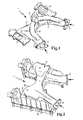
- FIG. 1 shows a view of a component 1 of a suction tube arrangement shown a so-called transverse channel 12th and part of the intake system of one here not shown internal combustion engine, in particular a V-Motors, is.
- Via connection flanges 2 and 3 Clean air sucked in for combustion and via a connection flange 4 is a recirculation of exhaust gas (EGR) made, via integrated into the component 1 channels 5 and 6 headed and at not visible here Einleitstellen within the component 1 admixed to the clean air becomes.
- EGR exhaust gas
- connection flanges 7 and 8 which over the Transverse channel 12 are interconnected, the component 1 attached to the cylinder head of the V-engine used here.
- connection parts 9 and 10 of such a V-engine shown, wherein the component 1 here from the rear view opposite the view from Figure 1 can be seen.
- the large-volume one-piece component for example a Aluminum casting, thus ensuring an excellent thermal coupling of the connection flange 4 of the exhaust gas recirculation to the transverse channel 12 for faster cooling and also allows for easy determination the respective mixing section with the clean air.
- the inventive Arrangement is in all internal combustion engines applicable where exhaust gas recirculation (EGR) is not in the cylinder head is integrated.
Landscapes
- Engineering & Computer Science (AREA)
- Chemical & Material Sciences (AREA)
- Combustion & Propulsion (AREA)
- Mechanical Engineering (AREA)
- General Engineering & Computer Science (AREA)
- Cylinder Crankcases Of Internal Combustion Engines (AREA)
- Exhaust-Gas Circulating Devices (AREA)
- Exhaust Silencers (AREA)
Abstract
Description
Claims (5)
- Saugrohranordnung für einen Verbrennungsmotor, bei derQuerkanäle (12) zwischen den Saugkanälen vor den Zylindereinlässen eines mehrzylindrigen Verbrennungsmotors und eine Abgasrückführung angeordnet sind, dadurch gekennzeichnet, dassAnschlüsse (2,3) für die Reinlufteinleitung in die Saugkanäle, die Querkanäle (12) und einen Anschlussflansch (4) für die Abgasrückführungsleitung in ein einstückiges Bauteil (1) integriert sind, das an den jeweiligen Zylindereinlässen des Verbrennungsmotors anbringbar ist.
- Saugrohranordnung nach Anspruch 1, dadurch gekennzeichnet, dassder Anschlussflansch (4) für die Abgasrückleitung im Bereich der Mitte des jeweiligen Querkanals (12) angeordnet ist und die Zuführung des rückgeführten Abgases über entsprechenden Öffnungen in den Saugkanälen sich an jeweils vorgebbaren separaten Einleitstellen befindet.
- Saugrohranordnung nach Anspruch 1 oder 2, dadurch gekennzeichnet, dassdas einstückige Bauteil (1) ein Gussteil ist.
- Saugrohranordnung nach Anspruch 3, dadurch gekennzeichnet, dassdas Gussteil aus Aluminium ist.
- Saugrohranordnung nach einem der vorhergehenden Ansprüche, dadurch gekennzeichnet, dassder Verbrennungsmotor ein V-Motor mit einer abseits des Zylinderkopfs eingeleiteten Abgasrückführung ist.
Applications Claiming Priority (2)
| Application Number | Priority Date | Filing Date | Title |
|---|---|---|---|
| DE102004020102A DE102004020102A1 (de) | 2004-04-24 | 2004-04-24 | Saugrohranordnung für einen Verbrennungsmotor |
| DE102004020102 | 2004-04-24 |
Publications (1)
| Publication Number | Publication Date |
|---|---|
| EP1591654A1 true EP1591654A1 (de) | 2005-11-02 |
Family
ID=34939150
Family Applications (1)
| Application Number | Title | Priority Date | Filing Date |
|---|---|---|---|
| EP05102687A Withdrawn EP1591654A1 (de) | 2004-04-24 | 2005-04-05 | Saugrohranordnung für einen Verbrennungsmotor |
Country Status (4)
| Country | Link |
|---|---|
| US (1) | US7069894B2 (de) |
| EP (1) | EP1591654A1 (de) |
| JP (1) | JP2005307975A (de) |
| DE (1) | DE102004020102A1 (de) |
Families Citing this family (4)
| Publication number | Priority date | Publication date | Assignee | Title |
|---|---|---|---|---|
| US9938940B2 (en) | 2010-04-21 | 2018-04-10 | Ford Global Technologies, Llc | Intake manifold |
| US10815945B2 (en) | 2018-01-15 | 2020-10-27 | Ford Global Technologies, Llc | Integral intake manifold |
| US10801448B2 (en) | 2018-01-15 | 2020-10-13 | Ford Global Technologies, Llc | Integral intake manifold |
| US20190219012A1 (en) * | 2018-01-15 | 2019-07-18 | Ford Global Technologies, Llc | Integral intake manifold |
Citations (4)
| Publication number | Priority date | Publication date | Assignee | Title |
|---|---|---|---|---|
| EP0456957A1 (de) * | 1990-05-14 | 1991-11-21 | Dr.Ing.h.c. F. Porsche Aktiengesellschaft | Luftansauganlage einer Mehrzylinder-Brennkraftmaschine |
| US6167855B1 (en) * | 1998-06-12 | 2001-01-02 | Siemens Canada Limited | Integrated air-fuel module and assembly method |
| EP1074732A2 (de) * | 1999-08-06 | 2001-02-07 | Siemens Canada Limited | Verfahren zur Herstellung von Luftleitungen und Einspritzdüsenaufnahmestutzen |
| US6513507B2 (en) * | 2000-01-26 | 2003-02-04 | International Engine Intellectual Property Company, L.D.C. | Intake manifold module |
Family Cites Families (4)
| Publication number | Priority date | Publication date | Assignee | Title |
|---|---|---|---|---|
| FR2689936B1 (fr) * | 1992-04-09 | 1994-07-08 | Peugeot | Dispositif a rampe integree pour le recyclage des gaz d'echappement d'un moteur a combustion interne. |
| US5490488A (en) | 1995-04-05 | 1996-02-13 | Ford Motor Company | Internal combustion engine intake manifold with integral EGR cooler and ported EGR flow passages |
| DE19717040C1 (de) | 1997-04-23 | 1998-11-26 | Mannesmann Vdo Ag | Entlüftungsvorrichtung in einer zu einer Saugrohranordnung einer Brennkraftmaschine hinführenden Entlüftungsleitung |
| DE29811432U1 (de) | 1998-06-26 | 1998-09-03 | Filterwerk Mann & Hummel Gmbh, 71638 Ludwigsburg | Rohrsystem, insbesondere Saugrohrsystem für eine Brennkraftmaschine |
-
2004
- 2004-04-24 DE DE102004020102A patent/DE102004020102A1/de not_active Withdrawn
-
2005
- 2005-04-05 JP JP2005108442A patent/JP2005307975A/ja active Pending
- 2005-04-05 EP EP05102687A patent/EP1591654A1/de not_active Withdrawn
- 2005-04-21 US US11/110,796 patent/US7069894B2/en not_active Expired - Fee Related
Patent Citations (4)
| Publication number | Priority date | Publication date | Assignee | Title |
|---|---|---|---|---|
| EP0456957A1 (de) * | 1990-05-14 | 1991-11-21 | Dr.Ing.h.c. F. Porsche Aktiengesellschaft | Luftansauganlage einer Mehrzylinder-Brennkraftmaschine |
| US6167855B1 (en) * | 1998-06-12 | 2001-01-02 | Siemens Canada Limited | Integrated air-fuel module and assembly method |
| EP1074732A2 (de) * | 1999-08-06 | 2001-02-07 | Siemens Canada Limited | Verfahren zur Herstellung von Luftleitungen und Einspritzdüsenaufnahmestutzen |
| US6513507B2 (en) * | 2000-01-26 | 2003-02-04 | International Engine Intellectual Property Company, L.D.C. | Intake manifold module |
Also Published As
| Publication number | Publication date |
|---|---|
| US20050235941A1 (en) | 2005-10-27 |
| JP2005307975A (ja) | 2005-11-04 |
| US7069894B2 (en) | 2006-07-04 |
| DE102004020102A1 (de) | 2005-11-24 |
Similar Documents
| Publication | Publication Date | Title |
|---|---|---|
| DE60120967T2 (de) | Verfahren und vorrichtung zur abgasrückgewinnung und eine aufgeladene dieselkraftmaschine | |
| DE10116643C2 (de) | Hubkolbenbrennkraftmaschine | |
| DE102014100739B4 (de) | Teilweise integrierter abgaskrümmer | |
| DE102007062347B4 (de) | Kühlanordnung für einen Zylinderkopf einer Brennkraftmaschine | |
| DE102012207411A1 (de) | Ansaugkrümmerbaugruppe für dedizierte abgasrückführung | |
| EP1015750B1 (de) | Anordnung zur rückführung von abgas bei einem verbrennungsmotor | |
| EP2256314A1 (de) | Verbrennungsmotor | |
| DE4209684A1 (de) | Einrichtung zur Beeinflussung der Strömung in Gaswechselkanälen einer Brennkraftmaschine | |
| EP0908615B1 (de) | Abgasrückführventil | |
| DE102007057755A1 (de) | Zylinderkopf und Abgassystem eines Mehrzylindermotors | |
| DE102004020102A1 (de) | Saugrohranordnung für einen Verbrennungsmotor | |
| DE102010030793A1 (de) | Spiegelbild-Zylinderköpfe | |
| DE19920195B4 (de) | Luftansaugsystem für eine mehrzylindrige Brennkraftmaschine | |
| DE19940617A1 (de) | Ansaugkrümmer für Verbrennungsmotoren | |
| DE102004013206B4 (de) | Variable Kühlvorrichtung für zur Saugseite eines aufgeladenen Verbrennungsmotors rückgeführtes Abgas | |
| DE102009061764B4 (de) | Ansaugtrakt mit einem Ansaugmodul und mit einem Zylinderkopf | |
| DE60029809T2 (de) | Geformter einlasskrümmer mit separaten ansaugrohren | |
| DE4416251C1 (de) | Auslaßkanal an einer Brennkraftmaschine | |
| DE102022101656B4 (de) | Abgasrückführkühler, insbesondere für ein Kraftfahrzeug, sowie Kraftfahrzeug | |
| AT413862B (de) | Brennkraftmaschine mit einer ansaugvorrichtung | |
| DE20014711U1 (de) | Vorrichtung zur Rückführung von Gas an einem Verbrennungsmotor | |
| DE102018003350A1 (de) | Luftverteiler für eine Verbrennungskraftmaschine eines Kraftwagens, insbesondere eines Personenkraftwagens | |
| EP0394752B1 (de) | Flüssigkeitsgekühlte Verbrennungskraftmaschine mit Zwischenkühler | |
| WO2005057002A2 (de) | Brennkraftmaschine | |
| DE19741567B4 (de) | Hubkolben-Brennkraftmaschine |
Legal Events
| Date | Code | Title | Description |
|---|---|---|---|
| PUAI | Public reference made under article 153(3) epc to a published international application that has entered the european phase |
Free format text: ORIGINAL CODE: 0009012 |
|
| AK | Designated contracting states |
Kind code of ref document: A1 Designated state(s): AT BE BG CH CY CZ DE DK EE ES FI FR GB GR HU IE IS IT LI LT LU MC NL PL PT RO SE SI SK TR |
|
| AX | Request for extension of the european patent |
Extension state: AL BA HR LV MK YU |
|
| 17P | Request for examination filed |
Effective date: 20051115 |
|
| AKX | Designation fees paid |
Designated state(s): AT BE BG CH CY CZ DE DK EE ES FI FR GB GR HU IE IS IT LI LT LU MC NL PL PT RO SE SI SK TR |
|
| GRAP | Despatch of communication of intention to grant a patent |
Free format text: ORIGINAL CODE: EPIDOSNIGR1 |
|
| STAA | Information on the status of an ep patent application or granted ep patent |
Free format text: STATUS: THE APPLICATION IS DEEMED TO BE WITHDRAWN |
|
| 18D | Application deemed to be withdrawn |
Effective date: 20080209 |