EP1591391A1 - Wickelmaschine zum kontinuierlichen Aufwickeln einer Materialbahn - Google Patents
Wickelmaschine zum kontinuierlichen Aufwickeln einer Materialbahn Download PDFInfo
- Publication number
- EP1591391A1 EP1591391A1 EP05103315A EP05103315A EP1591391A1 EP 1591391 A1 EP1591391 A1 EP 1591391A1 EP 05103315 A EP05103315 A EP 05103315A EP 05103315 A EP05103315 A EP 05103315A EP 1591391 A1 EP1591391 A1 EP 1591391A1
- Authority
- EP
- European Patent Office
- Prior art keywords
- winding
- winding machine
- luftabquetschwalze
- roller
- machine
- Prior art date
- Legal status (The legal status is an assumption and is not a legal conclusion. Google has not performed a legal analysis and makes no representation as to the accuracy of the status listed.)
- Granted
Links
- 238000004804 winding Methods 0.000 title claims description 129
- 230000007246 mechanism Effects 0.000 claims abstract description 6
- 239000000463 material Substances 0.000 claims description 12
- 230000002093 peripheral effect Effects 0.000 claims description 9
- 241001417494 Sciaenidae Species 0.000 claims description 7
- 230000001105 regulatory effect Effects 0.000 claims description 6
- 238000006073 displacement reaction Methods 0.000 claims description 5
- 230000008878 coupling Effects 0.000 claims description 4
- 238000010168 coupling process Methods 0.000 claims description 4
- 238000005859 coupling reaction Methods 0.000 claims description 4
- 239000000123 paper Substances 0.000 description 7
- 230000008901 benefit Effects 0.000 description 6
- 230000015572 biosynthetic process Effects 0.000 description 3
- 239000011111 cardboard Substances 0.000 description 3
- 230000008859 change Effects 0.000 description 3
- 239000011087 paperboard Substances 0.000 description 3
- 238000000418 atomic force spectrum Methods 0.000 description 2
- 238000000576 coating method Methods 0.000 description 2
- 238000010438 heat treatment Methods 0.000 description 2
- 238000007761 roller coating Methods 0.000 description 2
- 230000009471 action Effects 0.000 description 1
- 230000002238 attenuated effect Effects 0.000 description 1
- 238000006243 chemical reaction Methods 0.000 description 1
- 239000011248 coating agent Substances 0.000 description 1
- 238000010276 construction Methods 0.000 description 1
- 238000013016 damping Methods 0.000 description 1
- 230000001419 dependent effect Effects 0.000 description 1
- 230000000694 effects Effects 0.000 description 1
- 238000004519 manufacturing process Methods 0.000 description 1
- 230000000284 resting effect Effects 0.000 description 1
- 238000000926 separation method Methods 0.000 description 1
- 238000011144 upstream manufacturing Methods 0.000 description 1
Images

Classifications
-
- B—PERFORMING OPERATIONS; TRANSPORTING
- B65—CONVEYING; PACKING; STORING; HANDLING THIN OR FILAMENTARY MATERIAL
- B65H—HANDLING THIN OR FILAMENTARY MATERIAL, e.g. SHEETS, WEBS, CABLES
- B65H18/00—Winding webs
- B65H18/08—Web-winding mechanisms
- B65H18/26—Mechanisms for controlling contact pressure on winding-web package, e.g. for regulating the quantity of air between web layers
-
- B—PERFORMING OPERATIONS; TRANSPORTING
- B65—CONVEYING; PACKING; STORING; HANDLING THIN OR FILAMENTARY MATERIAL
- B65H—HANDLING THIN OR FILAMENTARY MATERIAL, e.g. SHEETS, WEBS, CABLES
- B65H19/00—Changing the web roll
- B65H19/22—Changing the web roll in winding mechanisms or in connection with winding operations
- B65H19/2207—Changing the web roll in winding mechanisms or in connection with winding operations the web roll being driven by a winding mechanism of the centre or core drive type
-
- B—PERFORMING OPERATIONS; TRANSPORTING
- B65—CONVEYING; PACKING; STORING; HANDLING THIN OR FILAMENTARY MATERIAL
- B65H—HANDLING THIN OR FILAMENTARY MATERIAL, e.g. SHEETS, WEBS, CABLES
- B65H27/00—Special constructions, e.g. surface features, of feed or guide rollers for webs
-
- B—PERFORMING OPERATIONS; TRANSPORTING
- B65—CONVEYING; PACKING; STORING; HANDLING THIN OR FILAMENTARY MATERIAL
- B65H—HANDLING THIN OR FILAMENTARY MATERIAL, e.g. SHEETS, WEBS, CABLES
- B65H2408/00—Specific machines
- B65H2408/20—Specific machines for handling web(s)
- B65H2408/23—Winding machines
- B65H2408/2362—Winding machines with two secondary winding spools, e.g. on separate carriages
- B65H2408/2364—Winding machines with two secondary winding spools, e.g. on separate carriages with additional element for facilitating web roll change
Definitions
- the invention relates to a winding machine for continuously winding a Material web, in particular a paper or board web, on a spool to a winding roll, with a carrying drum, with the winding roll a nip (winding nip) forms, with a at least one transport device comprehensive storage, which guides the spool along a preferably horizontal guideway, and with a Lucasabquetschwalze mounted in the lower part of the winding machine, when reaching a desired layer thickness of the winding roll can be applied by means of at least one movement device.
- Such winding machines are for example from the European patent EP 0 483 092 B1 or from PCT Publication WO 98/52858 A1 (PR10706 WO) of the applicant and are known in particular in Machines for the production or refinement of material webs, such as paper or cardboard.
- European Patent EP 0 788 991 B1 (DE 691 32 424 T2) a winding machine for continuously winding a material web, in particular a paper or cardboard web, on a spool to a winding roll known.
- This winding machine includes a nip with the winding roll bil - dende carrying drum, at least one comprehensive a transport device Storing the tambour along a preferably horizontal guideway leads, and a mounted in the lower part of the winding machine Beerabquetschwalze, which can be applied to the winding roll. Also this Heilabquetschwalze serves the purpose already mentioned, the formation of trapped air between the individual layers of the winding roll by maintaining the line force to prevent and during the Tambour cafe the "wrapped" To maintain web tension.
- This object is according to the invention in a winding machine of the type mentioned achieved in that the Luftabquetschwalze a roll diameter in the range of 300 to 500 mm, preferably 350 to 400 mm and that the Heilabquetschwalze of several juxtaposed Segmented rollers consists, each of the front side by means of storage units on a machine width Carrier profile are arranged.
- the Luftabquetschwalze at least two, preferably three to five segment roles.
- the storage unit is preferably adjustable, preferably positionally regulated. This is an exact positioning of the corresponding segment role to create a desired, preferably uniform line power curve guaranteed. Any bumps in the surface contour of the almost fully wound winding roll, especially in the two edge regions, are compensated by a controlled positioning of the individual segment rolls. Thus, locally different contact forces are avoided.
- the technical Construction of the entire Lucasabquetsch raised also results in a high Dimensions self-damping system, which of the material web or From the winding roll induced vibrations largely eliminated.
- the adjustment or the positioning of the storage unit by means of at least a controlled adjusting mechanism, the at least one pneumatic, hydraulic and / or mechanical adjusting element of known design and operation includes.
- the bearing unit for example, profile side of a joint bearing and have a resilient and preferably adjustable storage.
- the joint storage is preferred on the winding roll side facing the storage unit and the yielding Storage preferably on the side facing away from the winding roller of the storage unit arranged. Moreover, this results in the smallest possible spread the optionally offset laying lines of the segmented rolls to the said Surface contour.
- the generation of different forces of action is in particular caused by a known control unit and monitored.
- the individual sections can in turn be regulated in groups, for example symmetrical to the material web.
- By generating different Effective forces in the individual sections can also be a desired Set pressure profile, which is especially for NCR papers and / or not exactly cylindrical winding rolls is an advantage.
- the pressure profile can in particular also to displace possibly trapped air to the outside serve the edges of the winding roll out, for example, with larger forces in the area of the railway center and smaller forces in the two edge areas.
- the segment rollers preferably by means of at least one preferably the front side of the Lucasabquetschwalze arranged drive unit drivable. This allows the segment rolls also before application to the surface contour on the peripheral speed be accelerated, so that once again a gentle, This means that jerkless application of the segmented rolls is made possible.
- the segment roll has a width in the range of 200 to 3,500 mm, preferably from 1,500 to 2,500 mm, depending on whether over the whole Width of the material web an equalization of the contact pressure (small width ranges) or take place only at the two edges of the material web compensation should (large width area in the middle of the train, small widths on the Web edges).
- the rubberized surface of the segmented roller points in preferably a hardness in the range of 50 to 200 P & J (Pussy & Jones), preferably from 80 to 120 P & J, on.
- the Luftabquetschwalze is in a peripheral region can be applied to the lateral surface of the winding roll, at least from the point of emergence the web on the outer surface of the winding roll to the vertical Low point of the winding roll is enough.
- Upstream and Downstream jobs provide one Effectiveness loss with respect to said avoidance.
- the Beerabquetschwalze is substantially linear, preferably horizontal and / or vertically, and / or substantially along a contour of a circle segment applied. These application movements result in practice in terms of their Regulations and agitated mass or mass changes advantages.
- Another advantage is that when forming an effective range between the winding roll and the Lucasabquetschwalze the parent effect in the effective range is adjustable by a displacement of the carrier profile. This will be a good one until in the last winding layers present winding result, that is, a winding roll with a defined, uniform winding hardness over the entire winding time, achieved as a fine adjustment of the active power in the effective range between the Winder and air squeegee also during the final Winding phase, in which no nip between the carrier drum and the winding roll more is present, is possible.
- the different types of storage and movement for the Carrying drum 5 are in particular in the German patent application DE 198 07 897 A1 (PR10678 DE) of the applicant; their content regarding the different ones Storage and movement types are hereby the subject of this Description made.
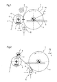
- the material web 2 is either from a calender, not shown here or a likewise not shown here dry section of a paper or Carried out carton machine, then initially wraps around a not shown Spreader roller and then runs in the direction of arrow on the lateral surface 6 of the Carrying drum 5, the outer surface 6 of the carrier drum 5 wraps around a certain angle (peripheral area) until it is detached by the resulting Winding 4.
- the detachment of the web 2 of the carrier drum 5 and the Conversion to the resulting winding roll 4 is done in the so-called nip (Winding nip) 7, which is during the main winding phase between the carrier drum 5 and the winding roll 4 forms.
- the winding roll 4 is by means of a lifting device, not shown, a movable Transport device in the movement direction indicated by the arrow P2 guided.
- the transport device can, for example, from a Spindle drive are formed, which is driven by an electric motor Includes threaded spindle.
- the transport device is used for holding and guiding of the preferably horizontal rails (guideway) 9 resting Tambours 3 of the reel 4.
- a device for regulating the Nip 7 line power L during the main winding phase is, for example, in the already mentioned German patent application DE 198 07 897 A1 (PR10678 DE) of the applicant.
- In the main winding phase shown in FIG becomes an empty tambour ("empty tambour") 8 of a not shown Holding device at a distance from the carrier drum 5 held ("standby position").
- a Heilabquetschwalze in dot-dashed form 10 including furnishings shown during the illustrated Main winding phase is in no active relationship with the winding roll 4. she stands rather in a waiting position.
- the Heilabquetschwalze 10 can generally with known mechanisms both substantially linear (arrows), preferably vertically as well as essentially along a contour of a circle segment (arrow) be moved and it is on reaching a desired thickness S to the Winding roller 4 can be applied by means of at least one known movement device.
- FIG. 2 shows a schematic side view of a winding machine 1 Beerabquetschwalze 10 according to the invention during the Endwickelphase. While This Endwickelphase is the winding roller 4 with the already described Transport device from the carrier drum 5 with resolution of the nip and under Training a free train moves away. The time is then offset previously held at a distance from the carrier drum 5 empty drum 8 of the holding device, not shown, on the carrier drum 5 with training a new nip 7 attached. With the web separation, not shown begins then the Anwickelphase for the empty drum 8, wherein the winding roller 4 then is no longer wound and horizontally (arrow P2) in an end position E (Tambour cookingposition) is moved.
- FIG. 3 shows a schematic illustration (cross section) of the invention Lucasabquetschwalze 10 during the Endwickelphase.
- the squeegee roller 10 has a roller diameter D in the range of 300 to 500 mm, preferably from 350 to 400 mm, and consists of several side by side mounted segment rollers 11, each front side means Storage units 12 are arranged on a machine-width carrier profile 13.
- the Luftabquetschwalze 10 preferably at least two, preferably three to five segment rollers 11.
- the storage unit 12 is adjustable, preferably regulated positionable, wherein their setting or their positioning by means of at least one controlled adjustment mechanism 14 takes place, the at least one pneumatic, hydraulic and / or mechanical adjustment element 15 includes.
- the adjusting element 15 can For example, as a controllable piston unit with hydraulic or pneumatic Be charged or executed as an electromechanical actuator.
- the Control R is only symbolically represented by an arrow.
- the storage unit profile side a Have joint support and a resilient and preferably adjustable storage, wherein the joint bearing usually facing on the winding roll Side of the storage unit is arranged and where the yielding and preferably adjustable storage as a rule on the winding roll facing away Side of the storage unit is arranged. It can be the joint storage directly to a arranged between two segment rollers bearing wall and be arranged on the machine-width carrier profile.
- the carrier profile 13 is shown in FIG. 3 a carrier tube with a rectangular and / or square tube cross-section. It can, however also have a polygonal pipe cross-section, if the application of this allows.
- the Luftabquetschwalze 10 in a Peripheral region U to the lateral surface 22 of the winding roll 4 is substantially linear, preferably vertically, and / or substantially along a contour of a Circular segment can be applied.
- the peripheral region U extends at least from the casserole point A of the web 2 on the lateral surface 22 of the winding roll 4 to the vertical Low point T of the winding roll 4th
- the Heilabquetschwalze 10 is before opening of the nip 7 ( Figure 1) between the Carrying drum 5 and the winding roller 4 to the winding roller 4 can be applied.
- an effective range W between the winding roll 4 and the Heilabquetschwalze 10 is the superordinate effective force K (arrow) in the effective range W by a Displacement of the carrier profile 13 adjustable.
- FIG. 4 shows a schematic and partial illustration (longitudinal section) of FIG Lucasabquetschwalze invention 10.
- the Heilabquetschwalze 10 consists, as already mentioned, of several side by side mounted segment rollers 11, each on the front side by means of bearing units 12 (double bearing unit between two segment rollers 11, single bearing unit on end segment roller 11) on a machine width, not shown Carrier profile are arranged.
- the Heilabquetschwalze 10 has at least two, preferably three to five segment rollers 11.
- the controlled storage units 12 are sectioned across the machine width M and in the individual sections S 1 to S N different Wirk specification K 1 to K N can be generated by means of the adjustment mechanisms 14. Moreover, the generation of different effective forces S 1 to S N in the individual sections S 1 to S N makes it possible to set a desired pressure profile, which is advantageous in particular for NCR papers and / or for not exactly cylindrical winding rolls.
- Two adjacent segment rollers 11 are in a common bearing sleeve 16th supported by roller bearings 17 and with an axle coupling 18 of known design Coupled with each other.
- segment rollers 11 by means of at least one preferably frontally the air squeezing 10 arranged drive unit 19 drive - bar, wherein in the figure 4, only the drive pulley 20 of the not explicitly shown Drive unit 19 is shown;
- the drive pulley 20 can also be designed as a drive pinion.
- the segment rollers 11 also before Application to the surface contour of the almost fully wound reel 4 the peripheral speed of the same are pre-accelerated, so that in turn a gentle, that is jerkless application of the segment rollers 11 allows becomes.
- the segmented rollers 11 have a width B in a range of 200 to 3,500 mm, preferably from 1,500 to 2,500 mm, on.
- segment rollers 11 rubberized ( Figure 3) and / or grooved Surfaces 21 on; Of course, they may also have flat surfaces 21.
- the rubberized surfaces 21 of the segment rollers 11 preferably have one Hardness H in the range of 50-200 P & J, preferably 80-120 P & J.
- a winding machine of the type mentioned is improved so that neither no Air pockets between the individual layers of the winding roll due to unevenness arise in the surface contour of the almost fully wound winding roll as well as a desired, preferably uniform line force profile between applied Lucasabquetschwalze and surface contour of almost full wound roll is given across the web width away.
Landscapes
- Winding Of Webs (AREA)
- Replacement Of Web Rolls (AREA)
Abstract
Description
- Figur 1:
- eine schematische Seitenansicht einer Wickelmaschine mit erfindungsgemäßer Luftabquetschwalze während der Hauptwickelphase;
- Figur 2:
- eine schematisierte Seitenansicht einer Wickelmaschine mit erfindungsgemäßer Luftabquetschwalze während der Endwickelphase;
- Figur 3:
- eine schematische Darstellung (Querschnitt) der erfindungsgemäßen Luftabquetschwalze; und
- Figur 4:
- eine schematische und teilweise Darstellung (Längsschnitt) der erfindungsgemäßen Luftabquetschwalze.
- 1
- Wickelmaschine
- 2
- Materialbahn
- 3
- Tambour
- 4
- Wickelrolle
- 5
- Tragtrommel
- 6
- Mantelfläche (Tragtrommel)
- 7
- Nip (Wickelspalt)
- 8
- Leerer Tambour ("Leertambour")
- 9
- Schiene (Führungsbahn)
- 10
- Luftabquetschvorrichtung
- 11
- Segmentrolle
- 11.1
- Endseitige Segmentrolle
- 12
- Lagereinheit
- 13
- Trägerprofil
- 14
- Verstellmechanismus
- 15
- Verstellelement
- 16
- Lagerhülse
- 17
- Wälzlager
- 18
- Achsenkupplung
- 19
- Antriebseinheit
- 20
- Antriebsscheibe
- 21
- Oberfläche
- 22
- Mantelfläche (Wickelrolle)
- A
- Auflaufpunkt
- B
- Breite
- D
- Durchmesser
- E
- Endposition
- G
- Horizontale Gerade
- H
- Härte
- K
- Wirkkraft (Pfeil)
- K1 bis KN
- Wirkkraft
- L
- Linienkraft
- P1
- Doppelpfeil
- P2
- Pfeil
- R
- Regelung (Pfeil)
- S
- Schichtdicke
- S1 bis SN
- Sektion
- T
- Tiefpunkt (Wickelrolle)
- U
- Umfangsbereich (Wickelrolle)
- W
- Wirkbereich
Claims (17)
- Wickelmaschine (1) zum kontinuierlichen Aufwickeln einer Materialbahn (2), insbesondere einer Papier- oder Kartonbahn, auf einen Tambour (3) zu einer Wickelrolle (4), mit einer Tragtrommel (5), die mit der Wickelrolle (4) einen Nip (7) bildet, mit einer mindestens eine Transporteinrichtung umfassenden Lagerung, die den Tambour (3) entlang einer bevorzugterweise horizontalen Führungsbahn (9) führt, und mit einer im unteren Bereich der Wickelmaschine (1) angebrachten Luftabquetschwalze (1 0), die bei Erreichen einer gewünschten Schichtdicke (S) an die Wickelrolle (4) mittels mindestens einer Bewegungseinrichtung anlegbar ist,
dadurch gekennzeichnet, dass die Luftabquetschwalze (10) einen Walzendurchmesser (D) im Bereich von 300 bis 500 mm, vorzugsweise von 350 bis 400 mm, aufweist und
dass die Luftabquetschwalze (10) aus mehreren nebeneinander gelagerten Segmentrollen (11, 11.1) besteht, die jeweils stirnseitig mittels Lagereinheiten (12) auf einem maschinenbreiten Trägerprofil (13) angeordnet sind. - Wickelmaschine (1) nach Anspruch 1,
dadurch gekennzeichnet, dass die Luftabquetschwalze (10) wenigstens zwei, vorzugsweise drei bis fünf Segmentrollen (11, 11.1). - Wickelmaschine (1) nach Anspruch 1 oder 2,
dadurch gekennzeichnet, dass die Lagereinheit (12) einstellbar, vorzugsweise geregelt positionierbar, ist. - Wickelmaschine (1) nach einem der vorhergehenden Ansprüche,
dadurch gekennzeichnet, dass die Einstellung bzw. die Positionierung der Lagereinheit (12) mittels wenigstens eines geregelten Verstellmechanismus (14) erfolgt, der mindestens ein pneumatisches, hydraulisches und/oder mechanisches Verstellelement (15) umfasst. - Wickelmaschine (1) nach einem der vorhergehenden Ansprüche,
dadurch gekennzeichnet, dass die Lagereinheit (12) profilseitig eine Gelenklagerung und eine nachgiebige und vorzugsweise regelbare Lagerung aufweist. - Wickelmaschine (1) nach Anspruch 5,
dadurch gekennzeichnet, dass die Gelenklagerung auf der der Wickelrolle (4) zugewandten Seite der Lagereinheit (12) angeordnet ist und
dass die nachgiebige und vorzugsweise regelbare Lagerung auf der der Wickelrolle (4) abgewandten Seite der Lagereinheit (12) angeordnet ist. - Wickelmaschine (1) nach einem der Ansprüche 3 bis 6,
dadurch gekennzeichnet, dass die geregelten Lagereinheiten (12) über die Maschinenbreite (M) hinweg sektioniert sind und
dass in den einzelnen Sektionen (S1 bis SN) unterschiedliche Wirkkräfte (K1 bis KN) erzeugbar sind. - Wickelmaschine (1) nach einem der vorhergehenden Ansprüche,
dadurch gekennzeichnet, dass zwei benachbarte Segmentrollen (11, 11.1) vorzugsweise mit einer
Achsenkupplung (18) miteinander koppelbar sind. - Wickelmaschine (1) nach einem der vorhergehenden Ansprüche,
dadurch gekennzeichnet, dass die Segmentrollen (11.1) mittels mindestens einer vorzugsweise stirnseitig der Luftabquetschwalze (10) angeordneten Antriebseinheit (19) antreibbar sind. - Wickelmaschine (1) nach einem der vorhergehenden Ansprüche,
dadurch gekennzeichnet, dass die Segmentrolle (11, 11.1) eine Breite (B) im Bereich von 200 bis 3.500 mm, vorzugsweise von 1.500 bis 2.500 mm, aufweist. - Wickelmaschine (1) nach einem der vorhergehenden Ansprüche,
dadurch gekennzeichnet, dass die Segmentrolle (11, 11.1) eine gummierte und/oder gerillte Oberfläche (21) aufweist. - Wickelmaschine (1) nach Anspruch 11,
dadurch gekennzeichnet, dass die gummierte Oberfläche (21) eine Härte (H) im Bereich von 50 bis 200 P&J, vorzugsweise von 80 bis 120 P&J, aufweist. - Wickelmaschine (1) nach einem der vorhergehenden Ansprüche,
dadurch gekennzeichnet, dass die Luftabquetschwalze (10) in einem Umfangsbereich (U) an die Mantelfläche (22) der Wickelrolle (4) anlegbar ist, der zumindest vom Auflaufpunkt (A) der Materialbahn (2) auf die Mantelfläche (22) der Wickelrolle (4) bis zum vertikalen Tiefpunkt (T) der Wickelrolle (4) reicht. - Wickelmaschine (1) nach einem der vorhergehenden Ansprüche,
dadurch gekennzeichnet, dass die Luftabquetschwalze (1 0) vor Öffnung des Nips (7) zwischen der Tragtrommel (5) und der Wickelrolle (4) an die Wickelrolle (4) anlegbar ist. - Wickelmaschine (1) nach einem der vorhergehenden Ansprüche,
dadurch gekennzeichnet, dass die Luftabquetschwalze (1 0) im Wesentlichen linear, vorzugsweise vertikal, anlegbar ist. - Wickelmaschine (1) nach einem der vorhergehenden Ansprüche,
dadurch gekennzeichnet, dass die Luftabquetschwalze (1 0) im Wesentlichen entlang einer Kontur eines Kreissegments anlegbar ist. - Wickelmaschine (1) nach einem der vorhergehenden Ansprüche,
dadurch gekennzeichnet, dass bei Ausbildung eines Wirkbereichs (W) zwischen der Wickelrolle (4) und der Luftabquetschwalze (10) die übergeordnete Wirkkraft (K) im Wirkbereich (W) durch eine Verlagerung des Trägerprofils (13) regelbar ist.
Applications Claiming Priority (2)
| Application Number | Priority Date | Filing Date | Title |
|---|---|---|---|
| DE102004020321 | 2004-04-26 | ||
| DE102004020321A DE102004020321A1 (de) | 2004-04-26 | 2004-04-26 | Wickelmaschine zum kontinuierlichen Aufwickeln einer Materialbahn |
Publications (2)
| Publication Number | Publication Date |
|---|---|
| EP1591391A1 true EP1591391A1 (de) | 2005-11-02 |
| EP1591391B1 EP1591391B1 (de) | 2009-06-24 |
Family
ID=34939474
Family Applications (1)
| Application Number | Title | Priority Date | Filing Date |
|---|---|---|---|
| EP05103315A Expired - Lifetime EP1591391B1 (de) | 2004-04-26 | 2005-04-25 | Wickelmaschine zum kontinuierlichen Aufwickeln einer Materialbahn |
Country Status (3)
| Country | Link |
|---|---|
| EP (1) | EP1591391B1 (de) |
| AT (1) | ATE434581T1 (de) |
| DE (2) | DE102004020321A1 (de) |
Cited By (3)
| Publication number | Priority date | Publication date | Assignee | Title |
|---|---|---|---|---|
| WO2010149404A1 (de) * | 2009-06-24 | 2010-12-29 | Voith Patent Gmbh | Wickelmaschine zum kontinuierlichen aufwickeln einer faserstoffbahn |
| EP3070035A1 (de) * | 2015-03-17 | 2016-09-21 | Seiko Epson Corporation | Transportvorrichtung und druckvorrichtung |
| CN105984245A (zh) * | 2015-03-17 | 2016-10-05 | 精工爱普生株式会社 | 输送装置以及印刷装置 |
Families Citing this family (1)
| Publication number | Priority date | Publication date | Assignee | Title |
|---|---|---|---|---|
| DE202008009998U1 (de) | 2008-07-25 | 2008-09-18 | Voith Patent Gmbh | Wickelmaschine zum kontinuierlichen Aufwickeln einer Materialbahn |
Citations (4)
| Publication number | Priority date | Publication date | Assignee | Title |
|---|---|---|---|---|
| US5836500A (en) * | 1996-02-27 | 1998-11-17 | Asselin | Guiding device using a non-bending segmented rotary roll |
| DE10023057A1 (de) * | 2000-05-11 | 2001-11-15 | Voith Paper Patent Gmbh | Wickelmaschine zum kontinuierlichen Aufwickeln einer Materialbahn |
| US20020042332A1 (en) * | 1999-03-22 | 2002-04-11 | Pekka Eronen | Segmented roll |
| US6409118B1 (en) * | 1998-10-21 | 2002-06-25 | Kampf Gmbh & Co. Maschinenfabrik | Contact rollers for a winding machine |
-
2004
- 2004-04-26 DE DE102004020321A patent/DE102004020321A1/de not_active Withdrawn
-
2005
- 2005-04-25 EP EP05103315A patent/EP1591391B1/de not_active Expired - Lifetime
- 2005-04-25 DE DE502005007547T patent/DE502005007547D1/de not_active Expired - Lifetime
- 2005-04-25 AT AT05103315T patent/ATE434581T1/de active
Patent Citations (4)
| Publication number | Priority date | Publication date | Assignee | Title |
|---|---|---|---|---|
| US5836500A (en) * | 1996-02-27 | 1998-11-17 | Asselin | Guiding device using a non-bending segmented rotary roll |
| US6409118B1 (en) * | 1998-10-21 | 2002-06-25 | Kampf Gmbh & Co. Maschinenfabrik | Contact rollers for a winding machine |
| US20020042332A1 (en) * | 1999-03-22 | 2002-04-11 | Pekka Eronen | Segmented roll |
| DE10023057A1 (de) * | 2000-05-11 | 2001-11-15 | Voith Paper Patent Gmbh | Wickelmaschine zum kontinuierlichen Aufwickeln einer Materialbahn |
Cited By (5)
| Publication number | Priority date | Publication date | Assignee | Title |
|---|---|---|---|---|
| WO2010149404A1 (de) * | 2009-06-24 | 2010-12-29 | Voith Patent Gmbh | Wickelmaschine zum kontinuierlichen aufwickeln einer faserstoffbahn |
| EP3070035A1 (de) * | 2015-03-17 | 2016-09-21 | Seiko Epson Corporation | Transportvorrichtung und druckvorrichtung |
| CN105984245A (zh) * | 2015-03-17 | 2016-10-05 | 精工爱普生株式会社 | 输送装置以及印刷装置 |
| US10093505B2 (en) | 2015-03-17 | 2018-10-09 | Seiko Epson Corporation | Transportation apparatus and printing apparatus |
| CN105984245B (zh) * | 2015-03-17 | 2020-06-09 | 精工爱普生株式会社 | 输送装置以及印刷装置 |
Also Published As
| Publication number | Publication date |
|---|---|
| DE102004020321A1 (de) | 2005-11-10 |
| ATE434581T1 (de) | 2009-07-15 |
| DE502005007547D1 (de) | 2009-08-06 |
| EP1591391B1 (de) | 2009-06-24 |
Similar Documents
| Publication | Publication Date | Title |
|---|---|---|
| EP0912435B1 (de) | Verfahren und wickelmaschine zum kontinuierlichen aufwickeln einer materialbahn | |
| EP0855355B1 (de) | Wickelmaschine und Verfahren zum kontinuierlichen Aufwickeln einer Materialbahn | |
| EP0792829B1 (de) | Verfahren zum Aufwickeln einer Papierbahn zu einer Rolle | |
| EP0921085B1 (de) | Verfahren und Wickelmaschine zum kontinuierlichen Aufwickeln einer Materialbahn | |
| EP0941955A2 (de) | Verfahren und Vorrichtung zum kontinuierlichen Aufwickeln einer Materialbahn | |
| DE69921179T2 (de) | Wickler und verfahren zum wickeln einer bahn | |
| EP1238933B1 (de) | Verfahren und Wickelmaschine zum kontinuierlichen Aufwickeln einer Materialbahn | |
| EP1167256A2 (de) | Verfahren und Wickelmaschine zum kontinuierlichen Aufwickeln einer Materialbahn | |
| EP1591390B1 (de) | Wickelmaschine zum kontinuierlichen Aufwickeln einer Materialbahn | |
| EP1591391B1 (de) | Wickelmaschine zum kontinuierlichen Aufwickeln einer Materialbahn | |
| DE19735590A1 (de) | Wickelmaschine zum Aufwickeln einer Materialbahn | |
| EP1153867A2 (de) | Wickelmaschine zum kontinuierlichen Aufwickeln einer Materialbahn | |
| EP1916209A2 (de) | Doppeltragwalzen-Wickelmaschine zum Aufwickeln einer Materialbahn | |
| EP1414726B2 (de) | Verfahren und wickelmaschine zum kontinuierlichen aufwickeln einer materialbahn | |
| DE60118964T2 (de) | Vorrichtung und verfahren zum wickeln von bahnen | |
| EP2445819A1 (de) | Wickelmaschine zum kontinuierlichen aufwickeln einer faserstoffbahn | |
| DE202008009998U1 (de) | Wickelmaschine zum kontinuierlichen Aufwickeln einer Materialbahn | |
| DE10251592B4 (de) | Tragwalzen-Wickelmaschine | |
| DE19748995A1 (de) | Verfahren und Wickelmaschine zum kontinuierlichen Aufwickeln einer Materialbahn | |
| EP2310306B1 (de) | Verfahren zum aufwickeln einer laufenden materialbahn sowie wickelmaschine zur durchführung des verfahrens | |
| DE20307581U1 (de) | Wickelmaschine zum kontinuierlichen Aufwickeln einer laufenden Materialbahn | |
| DE60009921T2 (de) | Verfahren zum verändern der linearen last bei einer wickelmaschine | |
| DE10218722A1 (de) | Verfahren und Wickelmaschine zum kontinuierlichen Aufwickeln einer Materialbahn | |
| DE202008014713U1 (de) | Wickelmaschine zum kontinuierlichen Aufwickeln einer Materialbahn | |
| EP1621496A2 (de) | Verfahren zum Überführen einer laufenden Faserstoffbahn auf einen Wickelkern sowie Vorrichtung zur Durchführung des Verfahrens |
Legal Events
| Date | Code | Title | Description |
|---|---|---|---|
| PUAI | Public reference made under article 153(3) epc to a published international application that has entered the european phase |
Free format text: ORIGINAL CODE: 0009012 |
|
| AK | Designated contracting states |
Kind code of ref document: A1 Designated state(s): AT BE BG CH CY CZ DE DK EE ES FI FR GB GR HU IE IS IT LI LT LU MC NL PL PT RO SE SI SK TR |
|
| AX | Request for extension of the european patent |
Extension state: AL BA HR LV MK YU |
|
| 17P | Request for examination filed |
Effective date: 20060502 |
|
| AKX | Designation fees paid |
Designated state(s): AT BE BG CH CY CZ DE DK EE ES FI FR GB GR HU IE IS IT LI LT LU MC NL PL PT RO SE SI SK TR |
|
| RAP1 | Party data changed (applicant data changed or rights of an application transferred) |
Owner name: VOITH PATENT GMBH |
|
| 17Q | First examination report despatched |
Effective date: 20070611 |
|
| GRAP | Despatch of communication of intention to grant a patent |
Free format text: ORIGINAL CODE: EPIDOSNIGR1 |
|
| RTI1 | Title (correction) |
Free format text: REELING MACHINE FOR CONTINUOUS WINDING OF A WEB MATERIAL |
|
| GRAS | Grant fee paid |
Free format text: ORIGINAL CODE: EPIDOSNIGR3 |
|
| GRAA | (expected) grant |
Free format text: ORIGINAL CODE: 0009210 |
|
| AK | Designated contracting states |
Kind code of ref document: B1 Designated state(s): AT BE BG CH CY CZ DE DK EE ES FI FR GB GR HU IE IS IT LI LT LU MC NL PL PT RO SE SI SK TR |
|
| REG | Reference to a national code |
Ref country code: GB Ref legal event code: FG4D Free format text: NOT ENGLISH |
|
| REG | Reference to a national code |
Ref country code: CH Ref legal event code: EP |
|
| REG | Reference to a national code |
Ref country code: IE Ref legal event code: FG4D Free format text: LANGUAGE OF EP DOCUMENT: GERMAN |
|
| REF | Corresponds to: |
Ref document number: 502005007547 Country of ref document: DE Date of ref document: 20090806 Kind code of ref document: P |
|
| PG25 | Lapsed in a contracting state [announced via postgrant information from national office to epo] |
Ref country code: LT Free format text: LAPSE BECAUSE OF FAILURE TO SUBMIT A TRANSLATION OF THE DESCRIPTION OR TO PAY THE FEE WITHIN THE PRESCRIBED TIME-LIMIT Effective date: 20090624 |
|
| PG25 | Lapsed in a contracting state [announced via postgrant information from national office to epo] |
Ref country code: SI Free format text: LAPSE BECAUSE OF FAILURE TO SUBMIT A TRANSLATION OF THE DESCRIPTION OR TO PAY THE FEE WITHIN THE PRESCRIBED TIME-LIMIT Effective date: 20090624 Ref country code: PL Free format text: LAPSE BECAUSE OF FAILURE TO SUBMIT A TRANSLATION OF THE DESCRIPTION OR TO PAY THE FEE WITHIN THE PRESCRIBED TIME-LIMIT Effective date: 20090624 Ref country code: SE Free format text: LAPSE BECAUSE OF FAILURE TO SUBMIT A TRANSLATION OF THE DESCRIPTION OR TO PAY THE FEE WITHIN THE PRESCRIBED TIME-LIMIT Effective date: 20090924 |
|
| NLV1 | Nl: lapsed or annulled due to failure to fulfill the requirements of art. 29p and 29m of the patents act | ||
| PG25 | Lapsed in a contracting state [announced via postgrant information from national office to epo] |
Ref country code: CZ Free format text: LAPSE BECAUSE OF FAILURE TO SUBMIT A TRANSLATION OF THE DESCRIPTION OR TO PAY THE FEE WITHIN THE PRESCRIBED TIME-LIMIT Effective date: 20090624 Ref country code: EE Free format text: LAPSE BECAUSE OF FAILURE TO SUBMIT A TRANSLATION OF THE DESCRIPTION OR TO PAY THE FEE WITHIN THE PRESCRIBED TIME-LIMIT Effective date: 20090624 Ref country code: ES Free format text: LAPSE BECAUSE OF FAILURE TO SUBMIT A TRANSLATION OF THE DESCRIPTION OR TO PAY THE FEE WITHIN THE PRESCRIBED TIME-LIMIT Effective date: 20091005 Ref country code: IS Free format text: LAPSE BECAUSE OF FAILURE TO SUBMIT A TRANSLATION OF THE DESCRIPTION OR TO PAY THE FEE WITHIN THE PRESCRIBED TIME-LIMIT Effective date: 20091024 |
|
| REG | Reference to a national code |
Ref country code: IE Ref legal event code: FD4D |
|
| PG25 | Lapsed in a contracting state [announced via postgrant information from national office to epo] |
Ref country code: SK Free format text: LAPSE BECAUSE OF FAILURE TO SUBMIT A TRANSLATION OF THE DESCRIPTION OR TO PAY THE FEE WITHIN THE PRESCRIBED TIME-LIMIT Effective date: 20090624 Ref country code: NL Free format text: LAPSE BECAUSE OF FAILURE TO SUBMIT A TRANSLATION OF THE DESCRIPTION OR TO PAY THE FEE WITHIN THE PRESCRIBED TIME-LIMIT Effective date: 20090624 |
|
| PG25 | Lapsed in a contracting state [announced via postgrant information from national office to epo] |
Ref country code: PT Free format text: LAPSE BECAUSE OF FAILURE TO SUBMIT A TRANSLATION OF THE DESCRIPTION OR TO PAY THE FEE WITHIN THE PRESCRIBED TIME-LIMIT Effective date: 20091024 Ref country code: BG Free format text: LAPSE BECAUSE OF FAILURE TO SUBMIT A TRANSLATION OF THE DESCRIPTION OR TO PAY THE FEE WITHIN THE PRESCRIBED TIME-LIMIT Effective date: 20090924 |
|
| PG25 | Lapsed in a contracting state [announced via postgrant information from national office to epo] |
Ref country code: IE Free format text: LAPSE BECAUSE OF FAILURE TO SUBMIT A TRANSLATION OF THE DESCRIPTION OR TO PAY THE FEE WITHIN THE PRESCRIBED TIME-LIMIT Effective date: 20090624 Ref country code: DK Free format text: LAPSE BECAUSE OF FAILURE TO SUBMIT A TRANSLATION OF THE DESCRIPTION OR TO PAY THE FEE WITHIN THE PRESCRIBED TIME-LIMIT Effective date: 20090624 |
|
| PLBE | No opposition filed within time limit |
Free format text: ORIGINAL CODE: 0009261 |
|
| STAA | Information on the status of an ep patent application or granted ep patent |
Free format text: STATUS: NO OPPOSITION FILED WITHIN TIME LIMIT |
|
| 26N | No opposition filed |
Effective date: 20100325 |
|
| PG25 | Lapsed in a contracting state [announced via postgrant information from national office to epo] |
Ref country code: GR Free format text: LAPSE BECAUSE OF FAILURE TO SUBMIT A TRANSLATION OF THE DESCRIPTION OR TO PAY THE FEE WITHIN THE PRESCRIBED TIME-LIMIT Effective date: 20090925 |
|
| BERE | Be: lapsed |
Owner name: VOITH PATENT G.M.B.H. Effective date: 20100430 |
|
| PG25 | Lapsed in a contracting state [announced via postgrant information from national office to epo] |
Ref country code: MC Free format text: LAPSE BECAUSE OF NON-PAYMENT OF DUE FEES Effective date: 20100430 |
|
| REG | Reference to a national code |
Ref country code: CH Ref legal event code: PL |
|
| GBPC | Gb: european patent ceased through non-payment of renewal fee |
Effective date: 20100425 |
|
| REG | Reference to a national code |
Ref country code: FR Ref legal event code: ST Effective date: 20101230 |
|
| PG25 | Lapsed in a contracting state [announced via postgrant information from national office to epo] |
Ref country code: CH Free format text: LAPSE BECAUSE OF NON-PAYMENT OF DUE FEES Effective date: 20100430 Ref country code: LI Free format text: LAPSE BECAUSE OF NON-PAYMENT OF DUE FEES Effective date: 20100430 |
|
| PG25 | Lapsed in a contracting state [announced via postgrant information from national office to epo] |
Ref country code: GB Free format text: LAPSE BECAUSE OF NON-PAYMENT OF DUE FEES Effective date: 20100425 Ref country code: BE Free format text: LAPSE BECAUSE OF NON-PAYMENT OF DUE FEES Effective date: 20100430 |
|
| PG25 | Lapsed in a contracting state [announced via postgrant information from national office to epo] |
Ref country code: FR Free format text: LAPSE BECAUSE OF NON-PAYMENT OF DUE FEES Effective date: 20100430 |
|
| PG25 | Lapsed in a contracting state [announced via postgrant information from national office to epo] |
Ref country code: CY Free format text: LAPSE BECAUSE OF FAILURE TO SUBMIT A TRANSLATION OF THE DESCRIPTION OR TO PAY THE FEE WITHIN THE PRESCRIBED TIME-LIMIT Effective date: 20090624 |
|
| PG25 | Lapsed in a contracting state [announced via postgrant information from national office to epo] |
Ref country code: HU Free format text: LAPSE BECAUSE OF FAILURE TO SUBMIT A TRANSLATION OF THE DESCRIPTION OR TO PAY THE FEE WITHIN THE PRESCRIBED TIME-LIMIT Effective date: 20091225 Ref country code: LU Free format text: LAPSE BECAUSE OF NON-PAYMENT OF DUE FEES Effective date: 20100425 |
|
| PG25 | Lapsed in a contracting state [announced via postgrant information from national office to epo] |
Ref country code: TR Free format text: LAPSE BECAUSE OF FAILURE TO SUBMIT A TRANSLATION OF THE DESCRIPTION OR TO PAY THE FEE WITHIN THE PRESCRIBED TIME-LIMIT Effective date: 20090624 |
|
| PGFP | Annual fee paid to national office [announced via postgrant information from national office to epo] |
Ref country code: AT Payment date: 20120411 Year of fee payment: 8 |
|
| PGFP | Annual fee paid to national office [announced via postgrant information from national office to epo] |
Ref country code: DE Payment date: 20130510 Year of fee payment: 9 |
|
| PGFP | Annual fee paid to national office [announced via postgrant information from national office to epo] |
Ref country code: IT Payment date: 20130528 Year of fee payment: 9 Ref country code: FI Payment date: 20130513 Year of fee payment: 9 |
|
| PG25 | Lapsed in a contracting state [announced via postgrant information from national office to epo] |
Ref country code: RO Free format text: LAPSE BECAUSE OF FAILURE TO SUBMIT A TRANSLATION OF THE DESCRIPTION OR TO PAY THE FEE WITHIN THE PRESCRIBED TIME-LIMIT Effective date: 20090624 |
|
| REG | Reference to a national code |
Ref country code: DE Ref legal event code: R119 Ref document number: 502005007547 Country of ref document: DE |
|
| REG | Reference to a national code |
Ref country code: AT Ref legal event code: MM01 Ref document number: 434581 Country of ref document: AT Kind code of ref document: T Effective date: 20140425 |
|
| REG | Reference to a national code |
Ref country code: DE Ref legal event code: R119 Ref document number: 502005007547 Country of ref document: DE Effective date: 20141101 |
|
| PG25 | Lapsed in a contracting state [announced via postgrant information from national office to epo] |
Ref country code: FI Free format text: LAPSE BECAUSE OF NON-PAYMENT OF DUE FEES Effective date: 20140425 Ref country code: DE Free format text: LAPSE BECAUSE OF NON-PAYMENT OF DUE FEES Effective date: 20141101 |
|
| PG25 | Lapsed in a contracting state [announced via postgrant information from national office to epo] |
Ref country code: AT Free format text: LAPSE BECAUSE OF NON-PAYMENT OF DUE FEES Effective date: 20140425 |
|
| PG25 | Lapsed in a contracting state [announced via postgrant information from national office to epo] |
Ref country code: IT Free format text: LAPSE BECAUSE OF NON-PAYMENT OF DUE FEES Effective date: 20140425 |