EP1591246A1 - Vorrichtung zur Zuführung von Strahlungsenergie auf einen Bedruckstoff - Google Patents
Vorrichtung zur Zuführung von Strahlungsenergie auf einen Bedruckstoff Download PDFInfo
- Publication number
- EP1591246A1 EP1591246A1 EP05102613A EP05102613A EP1591246A1 EP 1591246 A1 EP1591246 A1 EP 1591246A1 EP 05102613 A EP05102613 A EP 05102613A EP 05102613 A EP05102613 A EP 05102613A EP 1591246 A1 EP1591246 A1 EP 1591246A1
- Authority
- EP
- European Patent Office
- Prior art keywords
- radiant energy
- printing
- substrate
- light
- laser
- Prior art date
- Legal status (The legal status is an assumption and is not a legal conclusion. Google has not performed a legal analysis and makes no representation as to the accuracy of the status listed.)
- Granted
Links
- 238000007639 printing Methods 0.000 title claims abstract description 164
- 230000005855 radiation Effects 0.000 title claims description 55
- 239000000463 material Substances 0.000 title claims description 45
- 239000000758 substrate Substances 0.000 claims abstract description 71
- 239000004065 semiconductor Substances 0.000 claims description 4
- 238000012546 transfer Methods 0.000 claims description 4
- 239000000976 ink Substances 0.000 description 58
- 230000009102 absorption Effects 0.000 description 51
- 238000010521 absorption reaction Methods 0.000 description 51
- 238000001035 drying Methods 0.000 description 34
- 239000006096 absorbing agent Substances 0.000 description 30
- XLYOFNOQVPJJNP-UHFFFAOYSA-N water Substances O XLYOFNOQVPJJNP-UHFFFAOYSA-N 0.000 description 22
- 238000000034 method Methods 0.000 description 17
- 239000002904 solvent Substances 0.000 description 15
- 239000003086 colorant Substances 0.000 description 12
- 230000008033 biological extinction Effects 0.000 description 11
- 239000000654 additive Substances 0.000 description 10
- 230000008569 process Effects 0.000 description 10
- 239000000123 paper Substances 0.000 description 9
- 230000000996 additive effect Effects 0.000 description 8
- 230000000694 effects Effects 0.000 description 6
- 230000003287 optical effect Effects 0.000 description 6
- 239000000126 substance Substances 0.000 description 6
- 238000000862 absorption spectrum Methods 0.000 description 5
- 238000010438 heat treatment Methods 0.000 description 5
- 238000009434 installation Methods 0.000 description 5
- 230000031700 light absorption Effects 0.000 description 5
- 238000007645 offset printing Methods 0.000 description 5
- 239000011230 binding agent Substances 0.000 description 4
- 230000008859 change Effects 0.000 description 4
- 238000011161 development Methods 0.000 description 4
- 230000018109 developmental process Effects 0.000 description 4
- 238000001704 evaporation Methods 0.000 description 4
- 238000000265 homogenisation Methods 0.000 description 4
- 239000011347 resin Substances 0.000 description 4
- 229920005989 resin Polymers 0.000 description 4
- 230000018044 dehydration Effects 0.000 description 3
- 238000006297 dehydration reaction Methods 0.000 description 3
- 230000008020 evaporation Effects 0.000 description 3
- 239000000835 fiber Substances 0.000 description 3
- 239000003921 oil Substances 0.000 description 3
- 239000002245 particle Substances 0.000 description 3
- 239000000049 pigment Substances 0.000 description 3
- 238000006116 polymerization reaction Methods 0.000 description 3
- 238000012545 processing Methods 0.000 description 3
- 229910052769 Ytterbium Inorganic materials 0.000 description 2
- 230000008901 benefit Effects 0.000 description 2
- 239000011248 coating agent Substances 0.000 description 2
- 238000000576 coating method Methods 0.000 description 2
- 230000001419 dependent effect Effects 0.000 description 2
- 238000013461 design Methods 0.000 description 2
- 125000004915 dibutylamino group Chemical group C(CCC)N(CCCC)* 0.000 description 2
- 125000000524 functional group Chemical group 0.000 description 2
- 239000011521 glass Substances 0.000 description 2
- 239000000203 mixture Substances 0.000 description 2
- 238000013021 overheating Methods 0.000 description 2
- 238000000926 separation method Methods 0.000 description 2
- 239000007787 solid Substances 0.000 description 2
- 230000003595 spectral effect Effects 0.000 description 2
- 230000008961 swelling Effects 0.000 description 2
- NAWDYIZEMPQZHO-UHFFFAOYSA-N ytterbium Chemical compound [Yb] NAWDYIZEMPQZHO-UHFFFAOYSA-N 0.000 description 2
- ACQHEDKGDZYTAR-UHFFFAOYSA-N (2e)-2-[(2e)-2-[2-chloro-3-[(e)-2-(3-ethyl-1,1-dimethylbenzo[e]indol-3-ium-2-yl)ethenyl]cyclohex-2-en-1-ylidene]ethylidene]-3-ethyl-1,1-dimethylbenzo[e]indole;tetrafluoroborate Chemical compound F[B-](F)(F)F.C1=CC2=CC=CC=C2C(C2(C)C)=C1N(CC)\C2=C/C=C\1C(Cl)=C(\C=C\C=2C(C3=C4C=CC=CC4=CC=C3[N+]=2CC)(C)C)CCC/1 ACQHEDKGDZYTAR-UHFFFAOYSA-N 0.000 description 1
- DIZRNWDCRMTSMH-UHFFFAOYSA-N 1-(2-chlorophenyl)-2-(3,4-dimethoxyphenyl)ethane-1,2-dithione;nickel Chemical compound [Ni].C1=C(OC)C(OC)=CC=C1C(=S)C(=S)C1=CC=CC=C1Cl.C1=C(OC)C(OC)=CC=C1C(=S)C(=S)C1=CC=CC=C1Cl DIZRNWDCRMTSMH-UHFFFAOYSA-N 0.000 description 1
- SBSWJXLGTZHJDV-UHFFFAOYSA-N 1H-indol-1-ium perchlorate Chemical compound Cl(=O)(=O)(=O)[O-].[NH2+]1C=CC2=CC=CC=C12 SBSWJXLGTZHJDV-UHFFFAOYSA-N 0.000 description 1
- OKTJSMMVPCPJKN-UHFFFAOYSA-N Carbon Chemical compound [C] OKTJSMMVPCPJKN-UHFFFAOYSA-N 0.000 description 1
- 229910052691 Erbium Inorganic materials 0.000 description 1
- 240000002329 Inga feuillei Species 0.000 description 1
- CBENFWSGALASAD-UHFFFAOYSA-N Ozone Chemical compound [O-][O+]=O CBENFWSGALASAD-UHFFFAOYSA-N 0.000 description 1
- RTAQQCXQSZGOHL-UHFFFAOYSA-N Titanium Chemical compound [Ti] RTAQQCXQSZGOHL-UHFFFAOYSA-N 0.000 description 1
- 230000002745 absorbent Effects 0.000 description 1
- 239000002250 absorbent Substances 0.000 description 1
- 239000011358 absorbing material Substances 0.000 description 1
- 238000013459 approach Methods 0.000 description 1
- 238000000149 argon plasma sintering Methods 0.000 description 1
- QVGXLLKOCUKJST-UHFFFAOYSA-N atomic oxygen Chemical compound [O] QVGXLLKOCUKJST-UHFFFAOYSA-N 0.000 description 1
- 230000009286 beneficial effect Effects 0.000 description 1
- 230000005540 biological transmission Effects 0.000 description 1
- 230000015572 biosynthetic process Effects 0.000 description 1
- 229910052799 carbon Inorganic materials 0.000 description 1
- 239000011111 cardboard Substances 0.000 description 1
- 238000006243 chemical reaction Methods 0.000 description 1
- 230000008878 coupling Effects 0.000 description 1
- 238000010168 coupling process Methods 0.000 description 1
- 238000005859 coupling reaction Methods 0.000 description 1
- 238000000354 decomposition reaction Methods 0.000 description 1
- 238000009792 diffusion process Methods 0.000 description 1
- 238000000295 emission spectrum Methods 0.000 description 1
- UYAHIZSMUZPPFV-UHFFFAOYSA-N erbium Chemical compound [Er] UYAHIZSMUZPPFV-UHFFFAOYSA-N 0.000 description 1
- 125000000219 ethylidene group Chemical group [H]C(=[*])C([H])([H])[H] 0.000 description 1
- 239000000945 filler Substances 0.000 description 1
- 238000009472 formulation Methods 0.000 description 1
- 238000003384 imaging method Methods 0.000 description 1
- 230000010354 integration Effects 0.000 description 1
- 230000003993 interaction Effects 0.000 description 1
- 238000012423 maintenance Methods 0.000 description 1
- 239000000155 melt Substances 0.000 description 1
- 238000002844 melting Methods 0.000 description 1
- 230000008018 melting Effects 0.000 description 1
- 238000012544 monitoring process Methods 0.000 description 1
- 230000001590 oxidative effect Effects 0.000 description 1
- 229910052760 oxygen Inorganic materials 0.000 description 1
- 239000001301 oxygen Substances 0.000 description 1
- 239000003973 paint Substances 0.000 description 1
- 239000011087 paperboard Substances 0.000 description 1
- 125000001997 phenyl group Chemical group [H]C1=C([H])C([H])=C(*)C([H])=C1[H] 0.000 description 1
- 230000010287 polarization Effects 0.000 description 1
- 230000002028 premature Effects 0.000 description 1
- 229910052594 sapphire Inorganic materials 0.000 description 1
- 239000010980 sapphire Substances 0.000 description 1
- 238000001228 spectrum Methods 0.000 description 1
- 238000003756 stirring Methods 0.000 description 1
- 239000010936 titanium Substances 0.000 description 1
- 229910052719 titanium Inorganic materials 0.000 description 1
- 230000001960 triggered effect Effects 0.000 description 1
- 238000011144 upstream manufacturing Methods 0.000 description 1
- 239000002966 varnish Substances 0.000 description 1
- 238000010792 warming Methods 0.000 description 1
Images

Classifications
-
- B—PERFORMING OPERATIONS; TRANSPORTING
- B41—PRINTING; LINING MACHINES; TYPEWRITERS; STAMPS
- B41F—PRINTING MACHINES OR PRESSES
- B41F23/00—Devices for treating the surfaces of sheets, webs, or other articles in connection with printing
- B41F23/04—Devices for treating the surfaces of sheets, webs, or other articles in connection with printing by heat drying, by cooling, by applying powders
- B41F23/0403—Drying webs
- B41F23/0406—Drying webs by radiation
Definitions
- the invention relates to a device for supplying radiant energy to a Substrate according to the preamble of claim 1.
- Planographic printing machines such as lithographic printing machines, rotary printing presses, Offset printing machines and the like, which arcuate or web-shaped Substrates, especially paper, cardboard, paperboard and the like, process, known, which cause adhesion of the ink on the substrate or support by Radiation energy is supplied to the ink located on the substrate.
- UV inks cure by polymerization, which by Photoinitiation triggered by light in the ultraviolet, off.
- solvent-based printing inks which are both a physical and a subject to chemical drying process.
- the physical drying includes the evaporation of solvents and the diffusion into the substrate (knocking off), while under chemical drying or oxidative drying due to a Polymerization of the oils, resins, binders or oils contained in the color formulations the like is understood, if appropriate with the participation of atmospheric oxygen.
- the Drying processes are generally dependent on each other, as by the knocking the solvent a separation within the binder system between solvents and Resins takes place, causing the resin molecules to approach and possibly lighter can polymerize.
- UV inks are considered harmful and can only be disposed of separately become. Furthermore, the UV radiation produces ozone, so that expensive Absauginraumen or inerting measures are provided.
- the heatset drying machine has a high energy requirement and can excessive drying of the substrate and thus to an undesirable Cause ripple.
- siccatives drying accelerators, so-called siccatives, in the Printing ink easy to premature drying of the ink and thus to build up the Guide printing ink to the surfaces of the printing-unit rollers and cylinders. Of the Dosage of siccatives are consequently limited.
- DE 102 34 076 A1 describes, for example, a device for drying Printing ink on printing material sheets, wherein the device is a radiant energy source, In particular, a laser that emits light in the near IR range.
- the wavelength The IR radiation is chosen so that this non-resonant Absorption wavelengths of water, whereby only a heating of the color, However, not the bow can be achieved.
- unpublished DE 103 16 471 describes a process for drying a printing ink on a substrate, wherein the substrate with Laser radiation is applied, whose wavelength is between 350 nm and 700 nm and substantially resonant to an absorption wavelength of at least one Color pigments of the ink is. Besides the pigment, there is no further absorber substance necessary for the radiation.
- From the still unpublished DE 103 16 472 is also for example a Method for drying a printing ink on a printing material, wherein except the ink nor a primer or a coating on the substrate is applied and wherein the primer or the coating is suitable, a Accelerating the drying of the ink by absorbing a radiation to cause.
- EP 0 355 473 A2 discloses an apparatus for drying Printing products known which a radiation energy source in the form of a laser includes.
- the radiant energy is applied to the surface of the substrates, which is on a Move web by means of a transport device through the printing press, on a Position between individual printing units or after the last printing unit before or in directed to the boom.
- the radiation source can be a laser in the ultraviolet for UV colors or a laser light source in the infrared for heating solvent-containing Be printing inks.
- the radiant energy source is outside the printing press arranged to avoid that due to unavoidable or shieldable Heat loss unwanted parts of the printing press to be heated.
- an additional system component is separate from the print engine user Must be made available.
- An energy input to Drying of solvent-based inks is said to have the effect of evaporating the Solvent and / or the effect of Wegfurs in the substrate and / or the effect assist or promote the polymerization, while at the same time undesirable Side effects, such as in particular excessive heating of the solvent-based printing ink, which can lead to decomposition of components or overheating of the solvent, be avoided.
- the energy input should not only, as in the case of toner fixation, be introduced for melting particles.
- the problem may arise that the dried product has visible traces of the drying process. These tracks can z. B. be perceived as a longitudinal or transverse stripes in the product and the Affect the quality of the product produced.
- Object of the present invention is an improved device for the supply of Radiation energy to create a substrate, which allows the Drying process without visible unwanted changes of the printed product perform.
- the z. B. obtained by the homogenization optics homogeneity of the light of Radiation energy source according to the invention has a value of less than about 15% and most preferably has a value of less than about 10% or 5%, wherein the Percentage on the deviation of a lowest to a highest value in the lateral intensity of light 12 (peak-to-valley homogeneity) refers.
- An optimized with respect to the accuracy of the irradiation dose embodiment of the Invention provides that the position at which the light is transmitted to the substrate in the path the planographic printing machine meets chosen such that at this position the printing material in Propagation direction of the radiation performs substantially no movement.
- the power density does not vary more than 15% or the focus dimension no longer varies than 15% change. Preferably not more than 10% or 5%.
- the position is close to a counter-pressure cylinder or near a beater or near a transfer cylinder.
- a gripper bridge-free substrate transport device e.g. one (suction) Belt transport device (advantageously in a boom or at least one Downstream printing unit), provide, because due to the lack of gripper bridges the positioning at a small distance to the substrate or to the substrate path is possible and therefore to expect less / no interference from moving gripper bridges are.
- the radiant energy delivery device of the present invention may further be characterized in that the radiant energy source emits substantially only light whose wavelength is non-resonant to absorption wavelengths of water (H 2 O).
- the absorption of light energy by water at 20 ° Celsius is not greater than 10.0%, in a preferred embodiment is not greater than 1.0%, especially below 0.1%.
- the radiant energy source emits only very low intensity of light, preferably no light, which is resonant to absorption wavelengths of water (H 2 O).
- the radiation energy source is narrowband.
- the Radiation energy source can in this case, for example, up to ⁇ 50 nm width by one Emit wavelength, it can also be one or more individual spectroscopic act on narrow emission lines.
- the emission maximum of narrowband radiation energy source or the wavelength of the radiation energy between 700.00 nm and 3000.00 nm, preferably between 700.00 nm and 2500.00 nm, in particular between 800.00 nm and 1300.00 nm, in a sub-region of the so-called Window in paper absorption spectrum.
- Particularly advantageous is an emission at 870.00 nm ⁇ 50.00 nm and / or 1050.00 ⁇ 50.00 nm and / or 1250.00 nm ⁇ 50.00 nm and / or 1600.00 nm ⁇ 50.00 nm. From the available diode laser wavelengths moreover suitable: 808 nm, 860 nm, 880 nm, 940 nm, 980 nm (each ⁇ 10 nm).
- the following absorption by water, more precisely by water vapor results: at 808 nm less than 0.5%, at 870 ⁇ 10 nm less than 0.01 %, at 940 ⁇ 10 nm less than 10%, at 980 ⁇ 10 nm less than 0.5%, 1030 ⁇ 30 nm less than 0.01%, 1064 nm less than 0.01 nm, 1100nm less than 0.5 % and 1250 ⁇ 10 nm less than 0.01%.
- the air contains at an absolute humidity of 1.5% an amount of water of about 12 g.
- the light source is not more than 1m away from the substrate and the absolute humidity is not significantly above 1.5%, the above-mentioned absorptions are not exceeded by water and / or water vapor.
- An additional absorption can take place by the moisture content of the printing material, if the light penetrates through the ink layer to the substrate, or by fountain solution, which has been transferred to the sheet by the printing process.
- the printing ink may have different wavelengths absorb.
- the inventive device is on the Substrate ink in the planographic printing machine near-infrared light while avoiding water absorption wavelengths, for example by the Irradiation of only a few wavelengths of a light source emitting a line spectrum, offered.
- the ink may include an infrared absorbing agent.
- a coupling of the Light in the ink and / or absorption of the radiant energy in the Printing ink is generated, enabled, supported, improved by the infrared absorber or relieved.
- the energy input which to Formation of heat can lead to an accelerated drying of the Ink.
- a high temperature in the printing ink in the Color layer
- the infrared absorber also as infrared absorber, IR absorber, IR absorber substance or the like, on the one hand, a component in the Printing ink having a functional group which is in the near infrared or, on the other hand, may be an additive or additive which is the Add printing ink before printing or added.
- the printing ink may have been supplemented with an infrared absorbing agent or a component modified to an infrared absorbing agent.
- the Infrared absorber while doing the property that it has little or no absorption In the visible range of wavelengths, so that the color impression of the ink little or even not influenced or changed.
- a relatively high energy input directly into the printing ink, in particular supported by an infrared absorber, is possible in an advantageous manner, without an undesirable Energy input into the substrate to get.
- This is explained, on the one hand, by the fact that the light can not be absorbed directly by the substrate, and that the energy absorbed by the paint layer rises after fractions of a second Color and printing material distributed.
- the heat capacity and the proportions are distributed so that a short heating of the ink layer is possible before the entire printed sheet experiences a homogeneous moderate temperature increase. This is the result required total energy supply reduced.
- the selective energy supply can in particular be supported by the fact that a wavelength is irradiated, which resonant or quasi-resonant to absorption lines of a component of the ink or to an absorption line or absorption maximum of an infrared absorbing substance in the printing ink is.
- the absorption of the radiant energy in the ink is more than 30%, preferably 50%, in particular 75%, may even be more than 90%.
- the device according to the invention allows a Drying of the solvent-based ink on the substrate, without the Dehydration too strong to influence.
- the radiation energy source at least one Laser, wherein the laser may be a semiconductor laser or a solid state laser.
- the radiation energy source is preferably a laser.
- a broadband light source such as an IR carbon emitter, be used with a suitable filter arrangement, so that a Narrowband radiation energy source in combination arises.
- a filter can in particular be an interference filter.
- the laser is a semiconductor laser, (diode laser) or a solid-state laser (Titanium sapphire, erbium glass, NdYAG, Nd glass or the like).
- a solid-state laser can preferably be optically pumped by diode lasers.
- the solid-state laser can also be Fiber laser or fiber optic laser, preferably an Ytterbium fiber laser, which 300 provide up to 700 W of light output at the workplace at 1070 nm to 1100 nm can.
- such lasers can also be used to a limited extent be tunable.
- the output wavelength of the laser is variable. This allows tuning to a desired wavelength, for example, in resonance or quasi-resonance to an absorption wavelength of Component in the printing ink, in particular to an infrared absorbing material in the Printing ink to be achieved.
- the device has a plurality of radiation energy sources, which are arranged in a one-dimensional field, a two-dimensional field or a three-dimensional field and the light strikes the substrate at a number of positions, likewise lasers, in particular semiconductor lasers or Solid state lasers can be used.
- lasers in particular semiconductor lasers or Solid state lasers can be used.
- the energy introduced by the supply of radiant energy per area is between 100 and 10,000 mJ / cm 2 , preferably between 100 and 1000 mJ / cm 2 , in particular between 200 and 500 mJ / cm 2 .
- the irradiation of the printing material takes place for a period of time between 0.01 ms and 1 s, preferably between 0.1 ms and 100 ms, in particular between 1 ms and 10 ms.
- the entry of the radiation energy in the specified time periods can be achieved in a preferred embodiment by a line focus of the radiation, under which the printed sheet or the substrate is passed. Depending on the extension of the line focus in the direction of movement of the substrate and its velocity [m / s], the interaction time results. Further knowledge of the radiation density [W / cm 2 ] results in the irradiation of the substrates [mJ / cm 2 ].
- the on the printing material at a position incident light in its intensity and Exposure time for each radiant energy source independent of the others Radiation energy sources is controllable.
- a control unit independent of or integrated into the Machine control of the planographic printing press, be provided.
- the Radiation energy source parameters it is possible to supply the energy at different To regulate the positions of the printing stock.
- An energy supply can then cover the area be adapted to the substrate at the present position on the substrate.
- the inventive device with a Set up a plurality of radiant energy sources such that at a position on the Substrate light from at least two radiant energy sources impinges. It can on the one hand to partly on the other hand to completely overlapping light beam act. The required maximum output power of a single Radiation energy source is then lower, there is redundancy if a failure a radiation energy source occurs.
- a planographic printing machine according to the invention with at least one printing unit is characterized in that it comprises a device according to the invention for the supply of Radiation energy has.
- the planographic printing machine according to the invention can be a direct or indirect offset printing machine, a flexographic printing machine or the like.
- the position at which the light hits the substrate in the path through the Flat printing machine meets, the last printing nip of the last printing unit of the number of Be subordinate to printing units, so all pressure columns.
- the position also arranged downstream of a first pressure nip and upstream of a second pressure nip, so at least between two printing units, his.
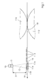
- FIG. 1 shows a schematic side view for explaining the arrangement of FIG Device according to the invention in a planographic printing machine.
- a radiation energy source 10 in particular a laser, preferably a diode laser or Solid-state laser is arranged within a planographic printing machine, that of her emitted light 12 on a substrate 14 on the path 16 through the Flat printing machine impinges on a position 116 which a pressure nip 18th is subordinate.
- the printing material 14 is shown by way of example arcuate, the Substrate also be web-like guided by the planographic printing machine.
- the orientation of the path 16 of the printing material 14 is indicated by an arrow.
- the path here is without limitation of a generally curved or non-linear course, in particular on a circular arc, shown linearly.
- the pressure nip 18 is in the embodiment shown in Figure 1 by the Collaboration of the pressure cylinder 110 and a counter-pressure cylinder 112 defined.
- the Pressure cylinder 110 may be a plate cylinder or a blanket cylinder.
- ink 114 On the substrate 14 ink 114 is shown. That of the radiant energy source 10 emitted light 12 falls in a bundle-shaped or carpet-like manner at a position 116 The printing material 14. Printing ink 114 within this position 116 can be energy from the Absorb light 12. By the preferred choice of a wavelength, which is non-resonant to absorption wavelengths of water, an absorption in the printing material 14 reduced.
- the distance D of the radiation energy source 10 from the surface of the printing material 14 is preferably between about 1 centimeter and about 30 Centimeters, more preferably between about 1 centimeter and about 10 centimeters selected.
- the radiation energy source 10 can for this purpose a homogenization optics 13 for have the light 12, which ensures that one of individual light spots or Lichtteillinien formed light line (eg., A laser line) of several laterally arranged Radiation energy source 10 in the line direction (lateral to the transport direction of the Stock 14) is substantially homogeneous in intensity.
- This optics can Be part of the radiation energy source 10 or be provided separately.
- the light line formed by the homogenization optics 13 preferably has an extension laterally to the transport direction of the printing substrate 14 of full substrate width. However, it can also be designed for a width of about 10 mm in order to realize modules for constructing a side-width lighting beam.
- Advantageous embodiments produce a focus in the transport direction of the printing substrate of 0.01 mm to 10 mm, depending on the printing speed (0.1 m / s - 30 m / s) the beneficial values of irradiation [W / cm 2 ] or [mJ / cm 2 ].
- focal distances between 0.1 mm and 10 mm or between 1 mm and 5 mm have proven to be advantageous at printing speeds between 1 m / s and 5 m / s.
- the homogenizing optics 13 may be light-guiding elements macroscopic or include microscopic dimension. Furthermore, the homogenizing optics 13 can be refractive, diffractive or reflective optical elements and combinations of such elements include.
- the homogeneity of the light 12 achieved by the homogenizing optics 13 Radiation energy source 10 preferably has a value of less than about 15% and most preferably has a value of less than about 10% or 5%, wherein the Percentage on the deviation of a lowest to a highest value in the lateral intensity of light 12 (peak-to-valley homogeneity) refers.
- the homogenizing optics 13 it can be achieved by the homogenizing optics 13 that the homogeneity the light in the transport direction of the printing material 14 is as high as possible, so that a short-term overheating of the color can be avoided as possible.
- the by the Homogenization optics 13 achieved homogeneity of the light 12 of the radiant energy source 10 in the transport direction of the printing material 14 preferably has a value of less than about 30%, and more preferably, less than about 20% or 10%.
- the percentage refers to the deviation of a lowest to a highest value in the intensity of the light 12 parallel to the transport direction (peak-to-valley homogeneity).
- an absorption element 118 on the radiation energy source 10th opposite side of the substrate 14 to provide such radiation absorbed, which was not absorbed by the ink 114 or the substrate 14.
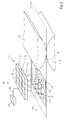
- Figure 2 is a schematic representation of an embodiment in an advantageous Development of the inventive device in a planographic printing machine. It is by way of example, a field 20 of radiant energy sources 10 is sketched, here three times four, that is twelve radiant energy sources 10.
- a one-dimensional field can also be used or a one-dimensional line, oriented over the width of the printing material 14 is provided be.
- Such a row may preferably be substantially wider sideways
- Lighting beam may be formed, for example, having a plurality of modules, the again comprise a number (for example 10) of laser diode bars 11, which in turn a number of laser diodes 11a, 11b, 11c etc.
- the laser diode bars 11 within the module both in a single Line can be arranged as well as in several staggered lines, so that advantageously a more compact design can be achieved.
- a laser diode bar 11 preferably has an output power between about 10 watts and about 200 watts, more preferably from about 50 - 100 watts. From the modular Structure of a lighting bar results from this preferably a power density between about 50 and about 500 watts per centimeter.
- a two-dimensional field, as well as a three-dimensional field whose light is in two-dimensional distribution on the substrate 14 has, among other things, the advantage that a rapid drying by parallel or simultaneous irradiation of a group of Positions in a column of the field 20 is achieved.
- the speed with which the printing material moves past the radiant energy sources 10, can therefore higher than in the case of a one-dimensional field.
- the series arrangement of several rows of radiant energy sources 10 is for example, the drying of colors with volatile components (heatset-like Colors) by successive evaporation of the components, for example solvents, effectively possible.
- preferably one or more Polarization divider can be used.
- the radiation of several Laser diode bar 11, which emit radiation of different wavelengths, via a Dichroic light guide can be united.
- Field 20 may also have a different number of radiant energy sources 10. From each of the number of radiant energy sources 10 becomes light 12 on the substrate 14 fed.
- Individual positions 116 may partially coincide, as shown in FIG. 2 for the leading line of radiant energy sources 10 is shown, or even in substantially completely overlap.
- the overlap leads to redundancy, whereby even if one fails Laser diode which at least partially drying the ink at the relevant point is guaranteed on the substrate 14.
- the field 20 of radiant energy sources 10 is a control device 24th associated with the that by means of a connection 22 can exchange control signals.
- the control device 24 can control the field 20 in such a way be performed that an energy supply according to the amount of ink on the Position 116 is performed on the substrate 14.
- the laser diodes 11a, 11b, 11c, etc. both individually or jointly switched on or off. Additionally or alternatively, be provided that the laser diodes 11 a, 11 b, 11 c, etc. both individually as also be varied in their performance together. This will allow that the drying at each point of the printing material 14 targeted there for drying necessary energy input is controllable. In this case, preferably information from prepress or pressure monitoring via the structure (color separations, Color distribution, areal coverage, color thickness) of the print image to be dried become.
- the ink can be dried so accurately on the substrate that too much warming and consequently too much evaporation of the Printing ink, especially with lateral fluctuations, can be avoided.
- the introduced radiation energy to 10%, more preferably 5% or even set only 1% accuracy.
- FIG. 3 schematically illustrates a planographic printing machine, in this embodiment a sheet-fed offset printing machine, with various alternative arrangements of Device according to the invention at the printing units or after the last printing unit represents.
- the planographic printing machine has four printing units 30, a feeder 32 and a Boom 34 on.
- various cylinders are shown which serve on the one hand for sheet guiding by the machine, on the other hand a planographic printing surface make available, be it directly as a plate cylinder or as a Transfer cylinder, in particular a blanket cylinder.
- Each printing unit 30 comprises a printing cylinder 110 and a counter-pressure cylinder 112, which has a pressure gap 18 define.
- a central radiant energy source 36 is shown, starting from the light by means of light-conducting elements 38, for example optical waveguides, Mirrors, imaging optics and the like, associated with the printing units 30 Projection elements 310 is guided.
- the projection elements 310 send light 12 Positions 116 on the path 16 of the printing material 14 by the planographic printing machine, which the respective printing columns 18 of the associated printing units 30 preferably are subordinate.
- light-guiding elements 38 it is possible to use the Radiation energy source 36 at a suitable location within the planographic printing machine to arrange at the sufficient space available.
- radiant energy sources 10 are shown, of which starting light 12 directly in positions 116 the pressure nip 18 of the respective printing unit 30 downstream of the path 16 of the printing material 14 is supplied.
- devices according to the invention for the supply of radiant energy can also in a web-processing printing press, in particular so-called Web-fed rotary presses, whether for commercial or newspaper printing, in be used advantageously.
- a radiant energy source 10, z. B. a substantially page widths Laser diode lighting beam, in the printing machine is preferably in one place chosen, at which the printing material 14 only slightly or substantially not at all Propagation direction of the radiation (the light 12) can move, d. H. for example a point at which the printing material 14 is moved substantially flutter-free.
- mounting locations 10 and 310 are particularly preferred a counter-pressure cylinder 112, but also installation locations 410 opposite one Turning drum 113 or provided in place of the turning drum transfer cylinder.
- the printing material 14 for example a paper sheet, of which each cylinder or the respective drum out and therefore leads a stable, im Essentially flutter-free movement.
- an installation location close to or close to a suction belt transport device such as. in a printing unit downstream dryer or Boom.
- the power density does not vary more than 15% or the focus dimension no longer varies than 15% change. Preferably not more than 10% or 5%.
- the focus adjustment may be changed and on the other at different printing speeds, d. H. at different transport paths of the substrate z. B. due to centrifugal forces, by the focus setting is kept constant.
- Infrarotabsorberstoff which by the location of its absorption maximum or his Absorption maxima in the so-called window of the paper absorption spectrum, in particular in the so-called window of the water absorption spectrum, is used.
- a required amount of the infrared absorbent material is used as an additive or additive of Add ink. This can, for example, by stirring the ink with the infrared absorber material outside or inside the planographic printing machine happen.
- An addition is usually only for the so-called bright colors, especially for the Four-color offset printing for the colors yellow, magenta and cyan (Y, M and C) makes sense.
- the required amount of infrared absorber material is calculated in a first approximation the Lambert-Beer extinction law, the layer thickness of the ink on the Substrate and the extinction coefficient.
- the on the Lambert-Beerschen Extinction law calculations are based in this presentation on immediate resonance, d. H. the emission wavelength is in the immediate vicinity of the absorption maximum. at slightly different laser wavelengths are obtained just as slightly different Absorption and requires accordingly, preferably proportionally more infrared absorber material. For the sake of completeness it should be mentioned that these considerations are relevant to practice Influence of light scattering and saturation effects not yet considered.
- the Light is substantially resonant to the absorption maximum of the Infrarotabsorberstoffes.
- the printing process in the planographic printing machine can in this embodiment without further Measures and performed without deviations from the conventional printing process become.
- infrared absorber 3-butyl-2 (2 - [- 2- (3-butyl-1,1-dimethyl-1,3-dihydro-benzo [e] indol-2-y -lidene) ethylidene] -2-chloro-cyclohex-1-enyl] -ethenyl) -1,1-dimethyl-1H-benzo [e] indolium perchlorate having the empirical formula C 46 H 52 Cl 2 N 2 O 4 and a molecular weight used of 767.84 g mol -1 .
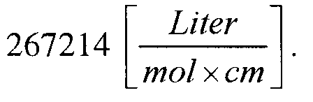
- This infrared absorber has an absorption maximum at 819 nm and a max.
- Extinction of 1.4 percent by weight of the infrared absorber material is required for about 90% laser light absorption as an additive in the colors C, M and Y for a layer thickness of 2 ⁇ m (according to Lambert-Beer extinction law). (For comparison: 0.9 weight percent for about 75%, 0.4 weight percent for about 50% and 0.2 weight percent for about 30%).
- the radiant energy delivery device includes a laser which emits at 808 nm as the radiant energy source, for example, an InGa (Al) As quantum well laser of the MB series from DILAS can be used.
- the mentioned laser from DILAS has a maximum optical output power of 24 W.
- the beam geometry after the collimator is 4 mm x 12 mm.
- the emission wavelength is thus sufficiently resonant to the absorption maximum of 819 ⁇ 15 nm; the infrared absorber shows an absorption greater than 50%.
- a beam profile and irradiation time of 2 ms have been chosen for an energy per area of 100 mJ / cm 2 .
- the absorption of radiation by water vapor in the air is less than 0.5%.
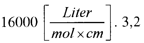
- This infrared absorber has an absorption maximum at 816 nm and a max. Extinction of Percent by weight of the infrared absorber material are required for about 90% laser light absorption as an additive in the colors C, M and Y for a layer thickness of 2 ⁇ m (according to Lambert-Beer extinction law). (For comparison: 0.5% by weight for about 75%, 0.3% by weight for about 50% and 0.1% by weight for about 30%).
- the radiant energy delivery device comprises as a source of radiant energy a laser emitting at 808 nm, for example a LIMO 100x 10x12 diode laser from LIMO may be used.
- the mentioned laser from LIMO has a maximum optical output power of 100 W.
- the beam geometry after the collimator is 10 mm x 12 mm.
- the emission wavelength is thus sufficiently resonant to the absorption maximum of 816 ⁇ 15 nm; the infrared absorber shows an absorption greater than 50%.
- a beam profile and irradiation time of 40 ms have been chosen for an energy per area of 833 mJ / cm 2 .
- the absorption of radiation by water vapor in the air is less than 0.5%.
- a third embodiment of the embodiment of the method according to the invention is as an infrared absorber benzenaminium-N, N'-2,5-cyclohexadiene-1,4-diylidenebis [4- (dibutylamino) -N- [4- (dibutylamino) phenyl] diperchlorate with the Molecular formula C 62 H 92 Cl 2 N 6 O 8 and a molecular weight of 1120.37 g mol -1 used.
- This infrared absorber has an absorption maximum at 1064 nm and a max.
- Extinction of Percent by weight of the infrared absorber material are required for about 50% laser light absorption as an additive in the colors C, M and Y for a layer thickness of 2 ⁇ m (according to Lambert-Beer extinction law). (For comparison: 15.9% by weight for about 90%, 9.6% by weight for about 75% and 2.5% by weight for about 30%).
- the radiant energy delivery device includes a laser emitting at 1075 nm as the radiant energy source, for example, an Ytterbium Fiber Laser YLR-100 from IPG Photonics may be used.
- the mentioned laser from IPG Photonics has a maximum optical output power of 100 W.
- the beam geometry in focus can be 3 mm x 3 mm.
- the emission wavelength is thus sufficiently resonant to the absorption maximum of 1064 ⁇ 15 nm; the infrared absorber shows an absorption greater than 50%.
- a beam profile and irradiation time of 5 ms and an energy per area of 417 mJ / cm 2 were selected.
- the absorption of radiation by water vapor in the air is below 0.1%.
- the infrared absorber used is bis (3,4-dimethoxy-2'-chlorodithiobenzil) nickel having the empirical formula C 32 H 26 Cl 2 NiO 4 S 4 and a molecular weight of 732.4 g mol -1 ,
- This infrared absorber has an absorption maximum at 885 nm and a max.
- Extinction of Percent by weight of the infrared absorber material are required for about 75% laser light absorption as an additive in the colors C, M and Y for a layer thickness of 2 ⁇ m (according to Lambert-Beer extinction law). (By comparison: 5.3% by weight for about 90%, 1.6% by weight for about 50% and 0.8% by weight for about 30%).
- the radiant energy delivery device includes as a radiant energy source a laser emitting at 870 nm, for example, a laser coupled laser diode system DLDFC-50 from Laser 2000 may be used.
- the mentioned Laser2000 laser has a maximum optical output power of 50 W and can be used in cw mode or pulsed mode.
- the emission wavelength is thus sufficiently resonant to the absorption maximum of 885 ⁇ 15 nm; the infrared absorber shows an absorption greater than 50%.
- a beam profile and irradiation time of 5 ms have been chosen for an energy per area of 152 mJ / cm 2 .
- the absorption of radiation by water vapor in the air is below 0.1%.
Landscapes
- Health & Medical Sciences (AREA)
- General Health & Medical Sciences (AREA)
- Toxicology (AREA)
- Engineering & Computer Science (AREA)
- Mechanical Engineering (AREA)
- Supply, Installation And Extraction Of Printed Sheets Or Plates (AREA)
Abstract
Description
- Figur 1
- eine schematische Seitendarstellung zur Erläuterung der Anordnung der erfindungsgemäßen Vorrichtung,
- Figur 2
- eine schematische, perspektivische Darstellung einer vorteilhaften Weiterbildung der erfindungsgemäßen Vorrichtung, und
- Figur 3
- eine schematische Seitendarstellung einer Flachdruckmaschine mit diversen alternativen Anordnungen der erfindungsgemäßen Vorrichtung an den Druckwerken bzw. nach dem letzten Druckwerk.


- 10
- Strahlungsenergiequelle/Einbauort der Strahlungsenergiequelle
- 11
- Laserdiodenbarren
- 11 a
- Laserdiode
- 11b
- Laserdiode
- 11c
- Laserdiode
- 12
- Licht
- 13
- Homogenisierungsoptik
- 14
- Bedruckstoff
- 16
- Pfad des Bedruckstoffes
- 18
- Druckspalt
- 110
- Druckzylinder
- 112
- Gegendruckzylinder
- 113
- Wendetrommel
- 114
- Druckfarbe
- 116
- Position auf dem Bedruckstoff
- 118
- Absorptionselement
- 20
- Feld von Strahlungsenergiequellen
- 22
- Verbindung zur Übertragung von Steuersignalen
- 24
- Steuerungseinheit
- 30
- Druckwerk
- 32
- Anleger
- 34
- Ausleger
- 36
- zentrale Strahlungsenergiequelle
- 38
- Lichtleitelement
- 310
- Projektionselement/Einbauort des Projektionselements
- 312
- alternative Strahlungsenergiequelle
- 314
- weitere alternative Strahlungsenergiequelle
- 410
- Strahlungsenergiequelle/Einbauort der Strahlungsenergiequelle
- D
- Abstand
Claims (10)
- Vorrichtung zur Zuführung von Strahlungsenergie auf einen Bedruckstoff (14) mit wenigstens einer Strahlungsenergiequelle (10), deren Licht (12) auf den Bedruckstoff (14) auf dem Pfad (16) des Bedruckstoffes (14) durch eine Druckmaschine an einer Position (116) trifft, welche wenigstens einem Druckspalt (18) in einem Druckwerk nachgeordnet ist,
dadurch gekennzeichnet, dass die Strahlungsenergiequelle (10) Licht (12) emittiert, welches in Querrichtung zur Richtung des Pfades (16) des Bedruckstoffes eine peak-to-valley-Homogenität von weniger als etwa 15% aufweist. - Vorrichtung zur Zuführung von Strahlungsenergie gemäß Anspruch 1,
dadurch gekennzeichnet,
die peak-to-valley-Homogenität weniger als etwa 10% oder weniger als etwa 5% beträgt. - Vorrichtung zur Zuführung von Strahlungsenergie gemäß Anspruch 1 oder 2,
dadurch gekennzeichnet, dass die Strahlungsenergiequelle (10) wenigstens einen Laser aufweist. - Vorrichtung zur Zuführung von Strahlungsenergie gemäß Anspruch 3,
dadurch gekennzeichnet, dass der Laser ein Halbleiterlaser oder ein Festkörperlaser ist. - Vorrichtung zur Zuführung von Strahlungsenergie gemäß einem der vorstehenden Ansprüche,
dadurch gekennzeichnet, dass die Vorrichtung eine Mehrzahl von Strahlungsenergiequellen (10) aufweist, die in einem eindimensionalen Feld, einem zweidimensionalen Feld (20) oder einem dreidimensionalen Feld angeordnet sind und deren Licht an einer Anzahl von Positionen (116) auf den Bedruckstoff (14) trifft. - Vorrichtung zur Zuführung von Strahlungsenergie gemäß einem der vorstehenden Ansprüche, welcher zusätzlich eine Steuerungseinheit (24) zugeordnet ist,
dadurch gekennzeichnet, dass das auf den Bedruckstoff (14) an einer Position (116) auftreffende Licht (12) in seiner Intensität und Belichtungsdauer für jede Strahlungsenergiequelle (10) unabhängig von den anderen Strahlungsenergiequellen (10) steuerbar ist. - Vorrichtung zur Zuführung von Strahlungsenergie gemäß einem der vorstehenden Ansprüche, dadurch gekennzeichnet, dass die Position (116), an der das Licht auf den Bedruckstoff (14) im Pfad (16) durch die Flachdruckmaschine trifft derart gewählt ist, dass an dieser Position (116) der Bedruckstoff (14) in Ausbreitungsrichtung der Strahlung im Wesentlichen keine Bewegung ausführt.
- Vorrichtung zur Zuführung von Strahlungsenergie gemäß Anspruch 7,
dadurch gekennzeichnet, dass die Position (116) nahe bei einem Gegendruckzylinders (112) oder nahe bei einer Wendetrommel (113), nahe bei einem Transferzylinder oder nahe bei einer Saugband-Transportvorrichtung gewählt ist. - Vorrichtung zur Zuführung von Strahlungsenergie gemäß einem der vorstehenden Ansprüche, dadurch gekennzeichnet, dass innerhalb einer Tiefenschärfe von etwa 1 bis 3 mm einer der Strahlungsenergiequelle (10) zugeordneten Optik die Leistungsdichte nicht mehr als etwa 15 % variiert, insbesondere nicht mehr als etwa 10 % oder 5 %, oder dass die Fokusdimension nicht mehr als etwa 15 % variiert, insbesondere nicht mehr als etwa 10 % oder 5 %.
- Flachdruckmaschine mit wenigstens einem Druckwerk (30),
gekennzeichnet durch
eine Vorrichtung zur Zuführung von Strahlungsenergie gemäß einem der vorstehenden Ansprüche.
Applications Claiming Priority (2)
| Application Number | Priority Date | Filing Date | Title |
|---|---|---|---|
| DE102004020454 | 2004-04-27 | ||
| DE102004020454A DE102004020454A1 (de) | 2004-04-27 | 2004-04-27 | Vorrichtung zur Zuführung von Strahlungsenergie auf einen Bedruckstoff |
Publications (2)
| Publication Number | Publication Date |
|---|---|
| EP1591246A1 true EP1591246A1 (de) | 2005-11-02 |
| EP1591246B1 EP1591246B1 (de) | 2012-06-13 |
Family
ID=34939112
Family Applications (1)
| Application Number | Title | Priority Date | Filing Date |
|---|---|---|---|
| EP05102613A Expired - Lifetime EP1591246B1 (de) | 2004-04-27 | 2005-04-04 | Vorrichtung zur Zuführung von Strahlungsenergie auf einen Bedruckstoff |
Country Status (5)
| Country | Link |
|---|---|
| US (1) | US8820236B2 (de) |
| EP (1) | EP1591246B1 (de) |
| JP (1) | JP2005313639A (de) |
| CN (1) | CN100462229C (de) |
| DE (1) | DE102004020454A1 (de) |
Cited By (3)
| Publication number | Priority date | Publication date | Assignee | Title |
|---|---|---|---|---|
| EP2258553A1 (de) * | 2009-06-05 | 2010-12-08 | WIFAG Maschinenfabrik AG | Vorrichtung und Verfahren zum Trocknen von Farbe auf einem bedruckten Substrat |
| EP2678132A1 (de) * | 2011-02-25 | 2014-01-01 | Saint-Gobain Glass France | Wärmebehandlung einer laserbeschichtung |
| EP2832549A1 (de) * | 2013-07-31 | 2015-02-04 | Gemalto SA | Vorrichtung zum Trocknen der Tintentropfen, und Punkt-für-Punkt-Tintenstrahldrucker, der eine solche Vorrichtung umfasst |
Families Citing this family (18)
| Publication number | Priority date | Publication date | Assignee | Title |
|---|---|---|---|---|
| KR100941590B1 (ko) * | 2007-03-09 | 2010-02-11 | 주식회사 엘지화학 | 음각 인쇄에 의한 미세패턴 인쇄방법 |
| DE102008013312A1 (de) | 2007-03-29 | 2008-10-02 | Heidelberger Druckmaschinen Ag | Verfahren zum Behandeln eines mit Druckfarbe bedruckten Bedruckstoff |
| DE102007058957A1 (de) * | 2007-12-07 | 2009-06-10 | Heidelberger Druckmaschinen Ag | Verfahren zum Trocknen von bedrucktem Material |
| DE102008056237B4 (de) * | 2007-12-07 | 2019-04-25 | Heidelberger Druckmaschinen Ag | Verfahren zum Trocknen von Druckfarbe und Druckfarbe |
| JP2009208463A (ja) | 2008-02-06 | 2009-09-17 | Ryobi Ltd | 印刷機の印刷方法及び印刷機 |
| DE102008035755A1 (de) * | 2008-07-31 | 2010-02-04 | Eastman Kodak Co. | Verfahren zum Trocknen eines Bedruckstoffs und/oder eines darauf befindlichen Druckmediums und eine Druckmaschine |
| JP2010042515A (ja) * | 2008-08-08 | 2010-02-25 | Mitsubishi Heavy Ind Ltd | インキ乾燥装置及び印刷機 |
| US8240841B2 (en) * | 2009-01-03 | 2012-08-14 | David M Caracciolo | Pulse drying system |
| EP2463100B1 (de) * | 2010-12-03 | 2013-07-17 | Heidelberger Druckmaschinen AG | Bogen verarbeitende Maschine, insbesondere Bogendruckmaschine |
| US8985756B2 (en) * | 2011-05-11 | 2015-03-24 | Ricoh Production Print Solutions LLC | Dynamic dryer control in printing |
| JP6140966B2 (ja) | 2011-10-14 | 2017-06-07 | キヤノン株式会社 | インプリント装置、それを用いた物品の製造方法 |
| DE102012209085A1 (de) * | 2012-05-30 | 2013-12-05 | Krones Ag | Lichtumlenkung bei Behälterbedruckung |
| US20130337191A1 (en) * | 2012-06-19 | 2013-12-19 | Intrinsiq Materials, Inc. | Method for depositing and curing nanoparticle-based ink using spatial light modulator |
| JP5983327B2 (ja) * | 2012-11-08 | 2016-08-31 | 富士ゼロックス株式会社 | 画像形成装置、定着装置、及び乾燥装置 |
| DE102015205066A1 (de) * | 2015-03-20 | 2016-09-22 | Koenig & Bauer Ag | Trocknereinrichtung für eine Druckmaschine, Druckmaschine sowie Verfahren zum Betrieb einer Trocknereinrichtung |
| DE102016204547A1 (de) * | 2016-03-18 | 2017-09-21 | Koenig & Bauer Ag | Verfahren zur Konfigurierung einer Trocknereinrichtung in einer Druckmaschine und eine Druckmaschine |
| DE102017107920A1 (de) * | 2017-04-12 | 2018-10-18 | Heraeus Noblelight Gmbh | Druckmaschine mit einer Infrarot-Trocknereinheit |
| WO2022025888A1 (en) | 2020-07-30 | 2022-02-03 | Hewlett-Packard Development Company, L.P. | Thermal treatment unit with spatially varying radiation power |
Citations (7)
| Publication number | Priority date | Publication date | Assignee | Title |
|---|---|---|---|---|
| EP0355473A2 (de) | 1988-08-25 | 1990-02-28 | Heidelberger Druckmaschinen Aktiengesellschaft | Vorrichtung zum Trocknen von Druckprodukten in einer Druckmaschine |
| EP0378826A2 (de) * | 1989-01-17 | 1990-07-25 | Heidelberger Druckmaschinen Aktiengesellschaft | Einrichtung zum Trocknen von Farben auf Papier |
| DE4435077A1 (de) | 1994-09-30 | 1995-11-09 | Siemens Nixdorf Inf Syst | Schnell schaltbare und höchstgeschwindigkeitsfähige Infrarotfixierung elektrografischer Tonerbilder |
| US6026748A (en) | 1997-11-11 | 2000-02-22 | Oxy-Dry Corporation | Infrared dryer system for printing presses |
| DE10234076A1 (de) | 2001-10-10 | 2003-04-24 | Heidelberger Druckmasch Ag | Vorrichtung und Verfahren zur Zuführung von Strahlungsenergie auf einem Bedruckstoff in einer Flachdruckmaschine |
| DE10316471A1 (de) | 2003-04-09 | 2004-10-28 | Heidelberger Druckmaschinen Ag | Verfahren zum Trocknen einer Druckfarbe auf einem Bedruckstoff und Druckwerk, geeignet zur Durchführung des Verfahrens |
| DE10316472A1 (de) | 2003-04-09 | 2004-10-28 | Heidelberger Druckmaschinen Ag | Verfahren zum Trocknen einer Druckfarbe auf einem Bedruckstoff in einer Druckmaschine und Druckmaschine |
Family Cites Families (20)
| Publication number | Priority date | Publication date | Assignee | Title |
|---|---|---|---|---|
| FR2653867B1 (fr) * | 1989-10-31 | 1992-08-21 | France Rayonnement | Ensemble de sechage par u.v. a plusieurs emetteurs. |
| US5558666A (en) * | 1994-01-14 | 1996-09-24 | Coherent, Inc. | Handpiece for producing highly collimated laser beam for dermatological procedures |
| JP3077879B2 (ja) * | 1994-02-15 | 2000-08-21 | インターナショナル・ビジネス・マシーンズ・コーポレ−ション | ウェブ・タイプの定量された処理材料にマイクロ波エネルギーを印加するための装置及び方法 |
| US5768017A (en) * | 1994-10-31 | 1998-06-16 | International Business Machines Corporation | Optical system for producing uniform line illumination |
| US6852948B1 (en) * | 1997-09-08 | 2005-02-08 | Thermark, Llc | High contrast surface marking using irradiation of electrostatically applied marking materials |
| DE19807643C2 (de) * | 1998-02-23 | 2000-01-05 | Industrieservis Ges Fuer Innov | Verfahren und Vorrichtung zum Trocknen eines Trocknungsgutes an der Oberfläche eines schnell geförderten Trägermaterials, insbesondere zum Druckfarbentrocknen |
| US6066830A (en) * | 1998-06-04 | 2000-05-23 | Astronics Corporation | Laser etching of electroluminescent lamp electrode structures, and electroluminescent lamps produced thereby |
| US6393042B1 (en) * | 1999-03-08 | 2002-05-21 | Semiconductor Energy Laboratory Co., Ltd. | Beam homogenizer and laser irradiation apparatus |
| US7271950B1 (en) * | 2000-02-16 | 2007-09-18 | Toppan Photomasks, Inc. | Apparatus and method for optimizing a pellicle for off-axis transmission of light |
| US6350071B1 (en) * | 2000-06-21 | 2002-02-26 | Intermec Ip Corp. | On demand printer apparatus and method with integrated UV curing |
| US6777170B1 (en) * | 2000-08-04 | 2004-08-17 | Massachusetts Institute Of Technology | Stereolithographic patterning by variable dose light delivery |
| EP1320462B1 (de) * | 2000-09-28 | 2004-10-06 | Creo IL.Ltd. | Gel-verfahren zum drucken variabler informationen |
| JP3534697B2 (ja) * | 2000-11-29 | 2004-06-07 | 三菱重工業株式会社 | 印刷用版材の作製方法、再生方法及び印刷機 |
| DE10145005C2 (de) * | 2000-12-22 | 2003-08-14 | Nexpress Solutions Llc | Verfahren und Einrichtung zur Fixierung von Toner auf einem Träger bzw. einem Bedruckstoff |
| US6832552B2 (en) * | 2001-06-26 | 2004-12-21 | Creo Inc. | Method of automated setting of imaging and processing parameters |
| US6873638B2 (en) * | 2001-06-29 | 2005-03-29 | 3M Innovative Properties Company | Laser diode chip with waveguide |
| CA2392429C (en) | 2001-07-23 | 2006-10-10 | Mitsubishi Heavy Industries, Ltd. | Sheet-fed press and intermediate cylinder for sheet-fed press |
| JP3935797B2 (ja) * | 2001-07-23 | 2007-06-27 | 三菱重工業株式会社 | 枚葉印刷機 |
| EP1302735B1 (de) * | 2001-10-10 | 2014-01-01 | Heidelberger Druckmaschinen Aktiengesellschaft | Vorrichtung und Verfahren zur Zuführung von Strahlungsenergie auf einen Bedruckstoff in einer Flachdruckmaschine |
| CN1659479A (zh) * | 2002-04-10 | 2005-08-24 | 富士胶片株式会社 | 曝光头及曝光装置和它的应用 |
-
2004
- 2004-04-27 DE DE102004020454A patent/DE102004020454A1/de not_active Withdrawn
-
2005
- 2005-04-04 EP EP05102613A patent/EP1591246B1/de not_active Expired - Lifetime
- 2005-04-14 JP JP2005116800A patent/JP2005313639A/ja active Pending
- 2005-04-26 US US11/114,282 patent/US8820236B2/en not_active Expired - Fee Related
- 2005-04-27 CN CNB2005100670428A patent/CN100462229C/zh not_active Expired - Fee Related
Patent Citations (7)
| Publication number | Priority date | Publication date | Assignee | Title |
|---|---|---|---|---|
| EP0355473A2 (de) | 1988-08-25 | 1990-02-28 | Heidelberger Druckmaschinen Aktiengesellschaft | Vorrichtung zum Trocknen von Druckprodukten in einer Druckmaschine |
| EP0378826A2 (de) * | 1989-01-17 | 1990-07-25 | Heidelberger Druckmaschinen Aktiengesellschaft | Einrichtung zum Trocknen von Farben auf Papier |
| DE4435077A1 (de) | 1994-09-30 | 1995-11-09 | Siemens Nixdorf Inf Syst | Schnell schaltbare und höchstgeschwindigkeitsfähige Infrarotfixierung elektrografischer Tonerbilder |
| US6026748A (en) | 1997-11-11 | 2000-02-22 | Oxy-Dry Corporation | Infrared dryer system for printing presses |
| DE10234076A1 (de) | 2001-10-10 | 2003-04-24 | Heidelberger Druckmasch Ag | Vorrichtung und Verfahren zur Zuführung von Strahlungsenergie auf einem Bedruckstoff in einer Flachdruckmaschine |
| DE10316471A1 (de) | 2003-04-09 | 2004-10-28 | Heidelberger Druckmaschinen Ag | Verfahren zum Trocknen einer Druckfarbe auf einem Bedruckstoff und Druckwerk, geeignet zur Durchführung des Verfahrens |
| DE10316472A1 (de) | 2003-04-09 | 2004-10-28 | Heidelberger Druckmaschinen Ag | Verfahren zum Trocknen einer Druckfarbe auf einem Bedruckstoff in einer Druckmaschine und Druckmaschine |
Cited By (3)
| Publication number | Priority date | Publication date | Assignee | Title |
|---|---|---|---|---|
| EP2258553A1 (de) * | 2009-06-05 | 2010-12-08 | WIFAG Maschinenfabrik AG | Vorrichtung und Verfahren zum Trocknen von Farbe auf einem bedruckten Substrat |
| EP2678132A1 (de) * | 2011-02-25 | 2014-01-01 | Saint-Gobain Glass France | Wärmebehandlung einer laserbeschichtung |
| EP2832549A1 (de) * | 2013-07-31 | 2015-02-04 | Gemalto SA | Vorrichtung zum Trocknen der Tintentropfen, und Punkt-für-Punkt-Tintenstrahldrucker, der eine solche Vorrichtung umfasst |
Also Published As
| Publication number | Publication date |
|---|---|
| EP1591246B1 (de) | 2012-06-13 |
| US20050235851A1 (en) | 2005-10-27 |
| DE102004020454A1 (de) | 2005-11-24 |
| CN1689807A (zh) | 2005-11-02 |
| JP2005313639A (ja) | 2005-11-10 |
| US8820236B2 (en) | 2014-09-02 |
| CN100462229C (zh) | 2009-02-18 |
Similar Documents
| Publication | Publication Date | Title |
|---|---|---|
| EP1302735B1 (de) | Vorrichtung und Verfahren zur Zuführung von Strahlungsenergie auf einen Bedruckstoff in einer Flachdruckmaschine | |
| EP1591246B1 (de) | Vorrichtung zur Zuführung von Strahlungsenergie auf einen Bedruckstoff | |
| DE10234076A1 (de) | Vorrichtung und Verfahren zur Zuführung von Strahlungsenergie auf einem Bedruckstoff in einer Flachdruckmaschine | |
| EP1466731B1 (de) | Verfahren zum Trocknen einer Druckfarbe auf einem Bedruckstoff in einer Druckmaschine und Druckmashine | |
| EP2067620B1 (de) | Verfahren zum Trocknen von bedrucktem Material im Mehrfarbdruck | |
| EP3049252B1 (de) | Rollen-tintenstrahldruckmaschine, druckfarbe und verfahren zum bedrucken eines bedruckstoffes | |
| EP2855161B1 (de) | Zusatz-druckeinrichtung in einer bogendruckmaschine | |
| EP3230187B1 (de) | Druckaggregat | |
| EP1466732B1 (de) | Verfahren zum Trocknen einer Druckfarbe auf einem Bedruckstoff und Druckwerk, geeignet zur Durchführung des Verfahrens | |
| EP3286008B1 (de) | Druckmaschine mit zumindest einem druckaggregat und zumindest einer trocknereinheit und ein verfahren zum betreiben einer druckmaschine | |
| EP2258553A1 (de) | Vorrichtung und Verfahren zum Trocknen von Farbe auf einem bedruckten Substrat | |
| EP3281800A1 (de) | Tintenstrahl-druckmaschine mit wenigstens zwei tintenstrahl-druckköpfen | |
| DE102015222753B4 (de) | Bearbeitungsvorrichtung für flaches Material und ein Verfahren zum Bearbeiten eines flachen Materials | |
| DE102012024393A1 (de) | Verfahren zum indirekten Auftragen von Druckflüssigkeit auf einen Bedruckstoff | |
| DE102020128849A1 (de) | Verfahren und Anordnung zur Herstellung eines bedruckten flächigen Verpackungsmaterials | |
| EP3921173A2 (de) | System und verfahren zum zwischentrocknen eines druckmediums | |
| DE102020123695A1 (de) | Vorrichtung zum Bestrahlen eines Fluids auf einem Bedruckstoff | |
| DE102013226843A1 (de) | Druckmaschine und Verfahren zum Bedrucken eines Bedruckstoffes | |
| DE102013226837A1 (de) | Druckmaschine und Verfahren zum Bedrucken eines Bedruckstoffes | |
| HK1055275B (en) | Device and method for supplying radiant energy onto a printing substrate in a planographic printing press | |
| DE102018110418A1 (de) | Einrichtung zum Zwischentrocknen von bedruckten Druckbögen | |
| HK1070862A (en) | Method for drying a printing ink on a printing substrate, and print unit suited for implementing the method |
Legal Events
| Date | Code | Title | Description |
|---|---|---|---|
| PUAI | Public reference made under article 153(3) epc to a published international application that has entered the european phase |
Free format text: ORIGINAL CODE: 0009012 |
|
| AK | Designated contracting states |
Kind code of ref document: A1 Designated state(s): AT BE BG CH CY CZ DE DK EE ES FI FR GB GR HU IE IS IT LI LT LU MC NL PL PT RO SE SI SK TR |
|
| AX | Request for extension of the european patent |
Extension state: AL BA HR LV MK YU |
|
| 17P | Request for examination filed |
Effective date: 20060502 |
|
| AKX | Designation fees paid |
Designated state(s): AT BE BG CH CY CZ DE DK EE ES FI FR GB GR HU IE IS IT LI LT LU MC NL PL PT RO SE SI SK TR |
|
| GRAP | Despatch of communication of intention to grant a patent |
Free format text: ORIGINAL CODE: EPIDOSNIGR1 |
|
| GRAS | Grant fee paid |
Free format text: ORIGINAL CODE: EPIDOSNIGR3 |
|
| GRAA | (expected) grant |
Free format text: ORIGINAL CODE: 0009210 |
|
| AK | Designated contracting states |
Kind code of ref document: B1 Designated state(s): AT BE BG CH CY CZ DE DK EE ES FI FR GB GR HU IE IS IT LI LT LU MC NL PL PT RO SE SI SK TR |
|
| REG | Reference to a national code |
Ref country code: GB Ref legal event code: FG4D Free format text: NOT ENGLISH |
|
| REG | Reference to a national code |
Ref country code: CH Ref legal event code: EP Ref country code: AT Ref legal event code: REF Ref document number: 561802 Country of ref document: AT Kind code of ref document: T Effective date: 20120615 |
|
| REG | Reference to a national code |
Ref country code: DE Ref legal event code: R081 Ref document number: 502005012811 Country of ref document: DE Owner name: HEIDELBERGER DRUCKMASCHINEN AG, DE Free format text: FORMER OWNER: HEIDELBERGER DRUCKMASCHINEN AG, 69115 HEIDELBERG, DE |
|
| REG | Reference to a national code |
Ref country code: IE Ref legal event code: FG4D Free format text: LANGUAGE OF EP DOCUMENT: GERMAN |
|
| REG | Reference to a national code |
Ref country code: DE Ref legal event code: R096 Ref document number: 502005012811 Country of ref document: DE Effective date: 20120809 |
|
| REG | Reference to a national code |
Ref country code: NL Ref legal event code: T3 |
|
| PG25 | Lapsed in a contracting state [announced via postgrant information from national office to epo] |
Ref country code: FI Free format text: LAPSE BECAUSE OF FAILURE TO SUBMIT A TRANSLATION OF THE DESCRIPTION OR TO PAY THE FEE WITHIN THE PRESCRIBED TIME-LIMIT Effective date: 20120613 Ref country code: CY Free format text: LAPSE BECAUSE OF FAILURE TO SUBMIT A TRANSLATION OF THE DESCRIPTION OR TO PAY THE FEE WITHIN THE PRESCRIBED TIME-LIMIT Effective date: 20120613 Ref country code: SE Free format text: LAPSE BECAUSE OF FAILURE TO SUBMIT A TRANSLATION OF THE DESCRIPTION OR TO PAY THE FEE WITHIN THE PRESCRIBED TIME-LIMIT Effective date: 20120613 Ref country code: LT Free format text: LAPSE BECAUSE OF FAILURE TO SUBMIT A TRANSLATION OF THE DESCRIPTION OR TO PAY THE FEE WITHIN THE PRESCRIBED TIME-LIMIT Effective date: 20120613 |
|
| REG | Reference to a national code |
Ref country code: LT Ref legal event code: MG4D Effective date: 20120606 |
|
| PG25 | Lapsed in a contracting state [announced via postgrant information from national office to epo] |
Ref country code: SI Free format text: LAPSE BECAUSE OF FAILURE TO SUBMIT A TRANSLATION OF THE DESCRIPTION OR TO PAY THE FEE WITHIN THE PRESCRIBED TIME-LIMIT Effective date: 20120613 Ref country code: GR Free format text: LAPSE BECAUSE OF FAILURE TO SUBMIT A TRANSLATION OF THE DESCRIPTION OR TO PAY THE FEE WITHIN THE PRESCRIBED TIME-LIMIT Effective date: 20120914 |
|
| PG25 | Lapsed in a contracting state [announced via postgrant information from national office to epo] |
Ref country code: EE Free format text: LAPSE BECAUSE OF FAILURE TO SUBMIT A TRANSLATION OF THE DESCRIPTION OR TO PAY THE FEE WITHIN THE PRESCRIBED TIME-LIMIT Effective date: 20120613 Ref country code: RO Free format text: LAPSE BECAUSE OF FAILURE TO SUBMIT A TRANSLATION OF THE DESCRIPTION OR TO PAY THE FEE WITHIN THE PRESCRIBED TIME-LIMIT Effective date: 20120613 Ref country code: IS Free format text: LAPSE BECAUSE OF FAILURE TO SUBMIT A TRANSLATION OF THE DESCRIPTION OR TO PAY THE FEE WITHIN THE PRESCRIBED TIME-LIMIT Effective date: 20121013 Ref country code: SK Free format text: LAPSE BECAUSE OF FAILURE TO SUBMIT A TRANSLATION OF THE DESCRIPTION OR TO PAY THE FEE WITHIN THE PRESCRIBED TIME-LIMIT Effective date: 20120613 Ref country code: CZ Free format text: LAPSE BECAUSE OF FAILURE TO SUBMIT A TRANSLATION OF THE DESCRIPTION OR TO PAY THE FEE WITHIN THE PRESCRIBED TIME-LIMIT Effective date: 20120613 |
|
| PG25 | Lapsed in a contracting state [announced via postgrant information from national office to epo] |
Ref country code: PL Free format text: LAPSE BECAUSE OF FAILURE TO SUBMIT A TRANSLATION OF THE DESCRIPTION OR TO PAY THE FEE WITHIN THE PRESCRIBED TIME-LIMIT Effective date: 20120613 Ref country code: IT Free format text: LAPSE BECAUSE OF FAILURE TO SUBMIT A TRANSLATION OF THE DESCRIPTION OR TO PAY THE FEE WITHIN THE PRESCRIBED TIME-LIMIT Effective date: 20120613 Ref country code: PT Free format text: LAPSE BECAUSE OF FAILURE TO SUBMIT A TRANSLATION OF THE DESCRIPTION OR TO PAY THE FEE WITHIN THE PRESCRIBED TIME-LIMIT Effective date: 20121015 |
|
| PLBE | No opposition filed within time limit |
Free format text: ORIGINAL CODE: 0009261 |
|
| STAA | Information on the status of an ep patent application or granted ep patent |
Free format text: STATUS: NO OPPOSITION FILED WITHIN TIME LIMIT |
|
| PG25 | Lapsed in a contracting state [announced via postgrant information from national office to epo] |
Ref country code: ES Free format text: LAPSE BECAUSE OF FAILURE TO SUBMIT A TRANSLATION OF THE DESCRIPTION OR TO PAY THE FEE WITHIN THE PRESCRIBED TIME-LIMIT Effective date: 20120924 Ref country code: DK Free format text: LAPSE BECAUSE OF FAILURE TO SUBMIT A TRANSLATION OF THE DESCRIPTION OR TO PAY THE FEE WITHIN THE PRESCRIBED TIME-LIMIT Effective date: 20120613 |
|
| 26N | No opposition filed |
Effective date: 20130314 |
|
| REG | Reference to a national code |
Ref country code: DE Ref legal event code: R097 Ref document number: 502005012811 Country of ref document: DE Effective date: 20130314 |
|
| PG25 | Lapsed in a contracting state [announced via postgrant information from national office to epo] |
Ref country code: BG Free format text: LAPSE BECAUSE OF FAILURE TO SUBMIT A TRANSLATION OF THE DESCRIPTION OR TO PAY THE FEE WITHIN THE PRESCRIBED TIME-LIMIT Effective date: 20120913 |
|
| BERE | Be: lapsed |
Owner name: HEIDELBERGER DRUCKMASCHINEN A.G. Effective date: 20130430 |
|
| PG25 | Lapsed in a contracting state [announced via postgrant information from national office to epo] |
Ref country code: MC Free format text: LAPSE BECAUSE OF FAILURE TO SUBMIT A TRANSLATION OF THE DESCRIPTION OR TO PAY THE FEE WITHIN THE PRESCRIBED TIME-LIMIT Effective date: 20120613 |
|
| GBPC | Gb: european patent ceased through non-payment of renewal fee |
Effective date: 20130404 |
|
| REG | Reference to a national code |
Ref country code: IE Ref legal event code: MM4A |
|
| PG25 | Lapsed in a contracting state [announced via postgrant information from national office to epo] |
Ref country code: BE Free format text: LAPSE BECAUSE OF NON-PAYMENT OF DUE FEES Effective date: 20130430 Ref country code: GB Free format text: LAPSE BECAUSE OF NON-PAYMENT OF DUE FEES Effective date: 20130404 |
|
| PG25 | Lapsed in a contracting state [announced via postgrant information from national office to epo] |
Ref country code: IE Free format text: LAPSE BECAUSE OF NON-PAYMENT OF DUE FEES Effective date: 20130404 |
|
| REG | Reference to a national code |
Ref country code: AT Ref legal event code: MM01 Ref document number: 561802 Country of ref document: AT Kind code of ref document: T Effective date: 20130404 |
|
| PG25 | Lapsed in a contracting state [announced via postgrant information from national office to epo] |
Ref country code: AT Free format text: LAPSE BECAUSE OF NON-PAYMENT OF DUE FEES Effective date: 20130404 |
|
| PG25 | Lapsed in a contracting state [announced via postgrant information from national office to epo] |
Ref country code: TR Free format text: LAPSE BECAUSE OF FAILURE TO SUBMIT A TRANSLATION OF THE DESCRIPTION OR TO PAY THE FEE WITHIN THE PRESCRIBED TIME-LIMIT Effective date: 20120613 |
|
| PG25 | Lapsed in a contracting state [announced via postgrant information from national office to epo] |
Ref country code: HU Free format text: LAPSE BECAUSE OF FAILURE TO SUBMIT A TRANSLATION OF THE DESCRIPTION OR TO PAY THE FEE WITHIN THE PRESCRIBED TIME-LIMIT; INVALID AB INITIO Effective date: 20050404 Ref country code: LU Free format text: LAPSE BECAUSE OF NON-PAYMENT OF DUE FEES Effective date: 20130404 |
|
| REG | Reference to a national code |
Ref country code: FR Ref legal event code: PLFP Year of fee payment: 12 |
|
| PGFP | Annual fee paid to national office [announced via postgrant information from national office to epo] |
Ref country code: CH Payment date: 20160423 Year of fee payment: 12 |
|
| REG | Reference to a national code |
Ref country code: DE Ref legal event code: R081 Ref document number: 502005012811 Country of ref document: DE Owner name: HEIDELBERGER DRUCKMASCHINEN AG, DE Free format text: FORMER OWNER: HEIDELBERGER DRUCKMASCHINEN AKTIENGESELLSCHAFT, 69115 HEIDELBERG, DE |
|
| REG | Reference to a national code |
Ref country code: FR Ref legal event code: PLFP Year of fee payment: 13 |
|
| REG | Reference to a national code |
Ref country code: CH Ref legal event code: PL |
|
| PG25 | Lapsed in a contracting state [announced via postgrant information from national office to epo] |
Ref country code: LI Free format text: LAPSE BECAUSE OF NON-PAYMENT OF DUE FEES Effective date: 20170430 Ref country code: CH Free format text: LAPSE BECAUSE OF NON-PAYMENT OF DUE FEES Effective date: 20170430 |
|
| REG | Reference to a national code |
Ref country code: FR Ref legal event code: PLFP Year of fee payment: 14 |
|
| PGFP | Annual fee paid to national office [announced via postgrant information from national office to epo] |
Ref country code: NL Payment date: 20200424 Year of fee payment: 16 Ref country code: FR Payment date: 20200420 Year of fee payment: 16 Ref country code: DE Payment date: 20200430 Year of fee payment: 16 |
|
| REG | Reference to a national code |
Ref country code: DE Ref legal event code: R119 Ref document number: 502005012811 Country of ref document: DE |
|
| REG | Reference to a national code |
Ref country code: NL Ref legal event code: MM Effective date: 20210501 |
|
| PG25 | Lapsed in a contracting state [announced via postgrant information from national office to epo] |
Ref country code: FR Free format text: LAPSE BECAUSE OF NON-PAYMENT OF DUE FEES Effective date: 20210430 Ref country code: DE Free format text: LAPSE BECAUSE OF NON-PAYMENT OF DUE FEES Effective date: 20211103 |
|
| PG25 | Lapsed in a contracting state [announced via postgrant information from national office to epo] |
Ref country code: NL Free format text: LAPSE BECAUSE OF NON-PAYMENT OF DUE FEES Effective date: 20210501 |
|
| P01 | Opt-out of the competence of the unified patent court (upc) registered |
Effective date: 20230404 |