EP1590146B1 - Vorrichtung zum abtrennen und abtransportieren von einem abgemessenen teil eines materials in einer anlage zur herstellung von artikeln durch pressformung und diese vorrichtung verwendendes verfahren - Google Patents
Vorrichtung zum abtrennen und abtransportieren von einem abgemessenen teil eines materials in einer anlage zur herstellung von artikeln durch pressformung und diese vorrichtung verwendendes verfahren Download PDFInfo
- Publication number
- EP1590146B1 EP1590146B1 EP03789419A EP03789419A EP1590146B1 EP 1590146 B1 EP1590146 B1 EP 1590146B1 EP 03789419 A EP03789419 A EP 03789419A EP 03789419 A EP03789419 A EP 03789419A EP 1590146 B1 EP1590146 B1 EP 1590146B1
- Authority
- EP
- European Patent Office
- Prior art keywords
- machine
- turntable
- auxiliary
- extrusion nozzle
- hand
- Prior art date
- Legal status (The legal status is an assumption and is not a legal conclusion. Google has not performed a legal analysis and makes no representation as to the accuracy of the status listed.)
- Expired - Lifetime
Links
- 239000000463 material Substances 0.000 title claims abstract description 23
- 238000000034 method Methods 0.000 title claims abstract description 4
- 238000000748 compression moulding Methods 0.000 title claims description 7
- 238000001125 extrusion Methods 0.000 claims abstract description 31
- 238000001816 cooling Methods 0.000 claims description 3
- 229920002994 synthetic fiber Polymers 0.000 claims 2
- 239000013598 vector Substances 0.000 abstract description 2
- 238000000926 separation method Methods 0.000 description 6
- 238000000465 moulding Methods 0.000 description 2
- 230000001105 regulatory effect Effects 0.000 description 2
- 238000011144 upstream manufacturing Methods 0.000 description 2
- 229920000297 Rayon Polymers 0.000 description 1
- 230000006835 compression Effects 0.000 description 1
- 238000007906 compression Methods 0.000 description 1
- 239000000110 cooling liquid Substances 0.000 description 1
- 230000007547 defect Effects 0.000 description 1
- 230000001747 exhibiting effect Effects 0.000 description 1
- 239000012530 fluid Substances 0.000 description 1
- 230000014759 maintenance of location Effects 0.000 description 1
- 239000012768 molten material Substances 0.000 description 1
- 230000002035 prolonged effect Effects 0.000 description 1
- 230000002269 spontaneous effect Effects 0.000 description 1
- 230000008961 swelling Effects 0.000 description 1
- 230000001360 synchronised effect Effects 0.000 description 1
Images
Classifications
-
- B—PERFORMING OPERATIONS; TRANSPORTING
- B29—WORKING OF PLASTICS; WORKING OF SUBSTANCES IN A PLASTIC STATE IN GENERAL
- B29C—SHAPING OR JOINING OF PLASTICS; SHAPING OF MATERIAL IN A PLASTIC STATE, NOT OTHERWISE PROVIDED FOR; AFTER-TREATMENT OF THE SHAPED PRODUCTS, e.g. REPAIRING
- B29C31/00—Handling, e.g. feeding of the material to be shaped, storage of plastics material before moulding; Automation, i.e. automated handling lines in plastics processing plants, e.g. using manipulators or robots
- B29C31/04—Feeding of the material to be moulded, e.g. into a mould cavity
- B29C31/042—Feeding of the material to be moulded, e.g. into a mould cavity using dispensing heads, e.g. extruders, placed over or apart from the moulds
- B29C31/048—Feeding of the material to be moulded, e.g. into a mould cavity using dispensing heads, e.g. extruders, placed over or apart from the moulds the material being severed at the dispensing head exit, e.g. as ring, drop or gob, and transported immediately into the mould, e.g. by gravity
-
- B—PERFORMING OPERATIONS; TRANSPORTING
- B29—WORKING OF PLASTICS; WORKING OF SUBSTANCES IN A PLASTIC STATE IN GENERAL
- B29C—SHAPING OR JOINING OF PLASTICS; SHAPING OF MATERIAL IN A PLASTIC STATE, NOT OTHERWISE PROVIDED FOR; AFTER-TREATMENT OF THE SHAPED PRODUCTS, e.g. REPAIRING
- B29C43/00—Compression moulding, i.e. applying external pressure to flow the moulding material; Apparatus therefor
- B29C43/32—Component parts, details or accessories; Auxiliary operations
- B29C43/34—Feeding the material to the mould or the compression means
- B29C2043/3433—Feeding the material to the mould or the compression means using dispensing heads, e.g. extruders, placed over or apart from the moulds
-
- B—PERFORMING OPERATIONS; TRANSPORTING
- B29—WORKING OF PLASTICS; WORKING OF SUBSTANCES IN A PLASTIC STATE IN GENERAL
- B29C—SHAPING OR JOINING OF PLASTICS; SHAPING OF MATERIAL IN A PLASTIC STATE, NOT OTHERWISE PROVIDED FOR; AFTER-TREATMENT OF THE SHAPED PRODUCTS, e.g. REPAIRING
- B29C43/00—Compression moulding, i.e. applying external pressure to flow the moulding material; Apparatus therefor
- B29C43/32—Component parts, details or accessories; Auxiliary operations
- B29C43/34—Feeding the material to the mould or the compression means
- B29C2043/3466—Feeding the material to the mould or the compression means using rotating supports, e.g. turntables or drums
-
- B—PERFORMING OPERATIONS; TRANSPORTING
- B29—WORKING OF PLASTICS; WORKING OF SUBSTANCES IN A PLASTIC STATE IN GENERAL
- B29C—SHAPING OR JOINING OF PLASTICS; SHAPING OF MATERIAL IN A PLASTIC STATE, NOT OTHERWISE PROVIDED FOR; AFTER-TREATMENT OF THE SHAPED PRODUCTS, e.g. REPAIRING
- B29C43/00—Compression moulding, i.e. applying external pressure to flow the moulding material; Apparatus therefor
- B29C43/32—Component parts, details or accessories; Auxiliary operations
- B29C43/36—Moulds for making articles of definite length, i.e. discrete articles
- B29C2043/3676—Moulds for making articles of definite length, i.e. discrete articles moulds mounted on rotating supporting constuctions
- B29C2043/3689—Moulds for making articles of definite length, i.e. discrete articles moulds mounted on rotating supporting constuctions on a support table, e.g. flat disk-like tables having moulds on the periphery
-
- B—PERFORMING OPERATIONS; TRANSPORTING
- B29—WORKING OF PLASTICS; WORKING OF SUBSTANCES IN A PLASTIC STATE IN GENERAL
- B29C—SHAPING OR JOINING OF PLASTICS; SHAPING OF MATERIAL IN A PLASTIC STATE, NOT OTHERWISE PROVIDED FOR; AFTER-TREATMENT OF THE SHAPED PRODUCTS, e.g. REPAIRING
- B29C43/00—Compression moulding, i.e. applying external pressure to flow the moulding material; Apparatus therefor
- B29C43/02—Compression moulding, i.e. applying external pressure to flow the moulding material; Apparatus therefor of articles of definite length, i.e. discrete articles
- B29C43/04—Compression moulding, i.e. applying external pressure to flow the moulding material; Apparatus therefor of articles of definite length, i.e. discrete articles using movable moulds
- B29C43/06—Compression moulding, i.e. applying external pressure to flow the moulding material; Apparatus therefor of articles of definite length, i.e. discrete articles using movable moulds continuously movable in one direction, e.g. mounted on chains, belts
- B29C43/08—Compression moulding, i.e. applying external pressure to flow the moulding material; Apparatus therefor of articles of definite length, i.e. discrete articles using movable moulds continuously movable in one direction, e.g. mounted on chains, belts with circular movement, e.g. mounted on rolls, turntables
-
- B—PERFORMING OPERATIONS; TRANSPORTING
- B29—WORKING OF PLASTICS; WORKING OF SUBSTANCES IN A PLASTIC STATE IN GENERAL
- B29C—SHAPING OR JOINING OF PLASTICS; SHAPING OF MATERIAL IN A PLASTIC STATE, NOT OTHERWISE PROVIDED FOR; AFTER-TREATMENT OF THE SHAPED PRODUCTS, e.g. REPAIRING
- B29C43/00—Compression moulding, i.e. applying external pressure to flow the moulding material; Apparatus therefor
- B29C43/32—Component parts, details or accessories; Auxiliary operations
- B29C43/34—Feeding the material to the mould or the compression means
-
- B—PERFORMING OPERATIONS; TRANSPORTING
- B29—WORKING OF PLASTICS; WORKING OF SUBSTANCES IN A PLASTIC STATE IN GENERAL
- B29L—INDEXING SCHEME ASSOCIATED WITH SUBCLASS B29C, RELATING TO PARTICULAR ARTICLES
- B29L2031/00—Other particular articles
- B29L2031/56—Stoppers or lids for bottles, jars, or the like, e.g. closures
- B29L2031/565—Stoppers or lids for bottles, jars, or the like, e.g. closures for containers
-
- Y—GENERAL TAGGING OF NEW TECHNOLOGICAL DEVELOPMENTS; GENERAL TAGGING OF CROSS-SECTIONAL TECHNOLOGIES SPANNING OVER SEVERAL SECTIONS OF THE IPC; TECHNICAL SUBJECTS COVERED BY FORMER USPC CROSS-REFERENCE ART COLLECTIONS [XRACs] AND DIGESTS
- Y10—TECHNICAL SUBJECTS COVERED BY FORMER USPC
- Y10S—TECHNICAL SUBJECTS COVERED BY FORMER USPC CROSS-REFERENCE ART COLLECTIONS [XRACs] AND DIGESTS
- Y10S425/00—Plastic article or earthenware shaping or treating: apparatus
- Y10S425/809—Seal, bottle caps only
Definitions
- the present patent relates generally to plants for forming articles by the known compression moulding method, and in particular relates to the feeding of sized portions of material into the cavity of the forming mould.
- the sized portions to be fed to the cavity of the forming mould are generally obtained by separation from a strip of extruded material.
- the strip can have a circular or approximately circular cross-section, which can be full or annular.
- the geometrical shape of the sized portion separated from the strip must be regular and free of surface defects.
- the means for separating and withdrawing the sized portion are generally positioned in the known art on a turntable which rotates adjacent to the extrusion nozzle, which is fixed and can be positioned below or above the separation and withdrawal means.
- the withdrawal means consist of a U-shaped element with its arms slightly diverging, associated with pneumatic means for retaining the sized portion or for releasing it where required, the element presenting its mouth facing forward with reference to the direction of rotation of the turntable on which it is arranged.
- the mouth is positioned "upstream", the terms “upstream” and “downstream” relating hereinafter to the direction of rotation of the turntable.
- Said means are known as the hand-like withdrawal element or simply hand-like element, and will be known as such hereinafter.
- the known art comprises means for cutting and separating the sized portion associated with the extrusion nozzle, and arranged to collaborate with the hand-like element.
- said separation or cutting means are positioned downstream of the hand-like element, and are rigid therewith.
- Systems are also known consisting of a sort of spring clutter in which the element which cuts off the sized portion simultaneously propels the plastic material into the mould.
- the velocity with which the material strip is cut through depends on the machine productivity and hence cannot be adjusted to the desired optimum velocity for separating the sized portion from the strip.
- the sized portions separated from the strip first come into contact with the hand-like element, which pushes them tangentially forward relative to the extrusion nozzle, and then come into contact with the cutting means consisting of a cutting blade which shaves the material on the extrusion nozzle only in that part of the sized portion which when separated is distant from the extrusion nozzle.
- That portion of the sized portion cut off may also appear torn because if the cutting velocity is not suitable, elastic viscose movements predominate within the molten material which lead to tearing instead of cutting of the material in the separation area.
- That portion of the sized portion which is the last to abandon the extrusion nozzle is therefore never subjected to correct cutting action, either because the cutting means act when said portion has already been separated from the strip, or because they act at an inconvenient velocity.
- Said upper portion therefore presents a surface with traces of the tearing action due to the passage of the hand-like element in contact with the extrusion nozzle.
- US 3955605 discloses an apparatus for providing a measured quantity of extrudate material to a plurality of continuously moving uniformly spaced receptacles on a rotating conveyor which can travel at varying speeds, wherein the extrudate material is severed by a cutting means having a cutting velocity independent of the feed rate of receptacles.
- US 4640673 discloses a compression molding apparatus comprising a rotary compression molding means including a rotating supporting member mounted rotatably about its central axis and a plurality of molding die means mounted on said rotating supporting member at circumferentially spaced intervals.
- US 5807592 discloses a machine as in the preamble of claim 1.
- the object of the present invention is to eliminate the aforestated drawbacks by means of a simple, reliable and economical solution. Said object is attained according to the invention by the characteristics defined in the claims.
- the cutting means are operated separately from the withdrawal means, which move relative to the extrusion nozzle with a velocity, in the sense of a vector, which is different from the velocity with which the hand-like element moves, the velocity with which the strip is cut to form the sized portion hence being independent of the machine productivity.
- Said cutting means can be mechanical, hydraulic or thermal.
- They can consists of a high velocity fluid jet or a laser beam.
- the cutting means have a temperature which is less than the temperature of the material to be treated by an amount sufficient to cause a localized viscosity increase of the material within the zone of or immediately close to the cut, without this negatively influencing the temperature, and hence the plasticity, of the remaining part of the sized portion.
- the cutting means of the invention are hence preferably, but not necessarily, cooled by external means.
- Said cooling means can conveniently consist of a cooling liquid circuit provided within the body of the cutting means and connected by rotary joints to the non-rotating fixed parts of the machine.
- the temperature difference between the cutting means and the material to be treated depends on various factors, such as the mass of the cutting means, their velocity relative to the material to be treated, and the plasticity and viscositycharacteristics of this latter.
- a convenient temperature difference between the temperature of the material to be treated and the cutting means is at least 5°C, preferably more than 20°C and possibly at least 50°C depending on the material to be treated.
- the cutting means consist of a rectilinear uncooled blade, but the blade can in reality have any shape, and could also comprise cooling means.
- the cutting means can precede or follow the passage of the hand-like element, depending on their type.
- the invention provides various embodiments, one of which is described hereinafter by way of non-limiting example.
- Said embodiment comprises an uncooled rectilinear blade, it being evidently also able to comprise blades of different form, such as cooled blades.
- the cutting means are conveniently but not necessarily positioned flush with the extrusion nozzle; depending on the velocity of the cutting means or their type, these latter can also be spaced from the extrusion nozzle.
- the means for withdrawing and transferring the sized portion from the extrusion nozzle commonly known as hand-like elements, are generally positioned circumferentially equidistant on a first auxiliary turntable rotating synchronously with the main turntable.
- the cutting means are positioned circumferentially on a second auxiliary turntable, equidistant from each other and from the axis of rotation of the turntable.
- Each cutting means can be fixed relative to the auxiliary turntable, or rotate about its own axis in such a manner as to be subjected to a planetary movement about its own axis, which itself rotates about the axis of the auxiliary turntable. This arrangement facilitates the ability to give the cutting means the desired velocity.
- the two circumferences on which the cutting means and the hand-like elements are respectively aligned are mutually tangential at a point which coincides with the axis of the extrusion nozzle.
- the extrusion nozzle can face downwards or upwards, in a generally vertical direction, the cutting means always being positioned between the extrusion nozzle and the hand-like elements.
- a third auxiliary turntable can be provided to facilitate passage of the sized portion from the first withdrawal and transfer turntable to the mould cavity.
- the axes of the first and second turntable are coaxial and the directions of rotation of the turntables are the same, but it will be apparent that the directions of rotation of the turntables can also be opposite, and that the axes of rotation of the two turntables can be positioned either on the same side or on opposite sides of the extrusion nozzle.
- the sized portion separated from the strip remains in the hand-like element which collects it either by spontaneous adhesion if exhibiting cohesion, or by the action of pneumatic suction means, or by mechanical retention by the known die swell phenomenon, or by swelling of the sized portion downstream of the extrusion nozzle.
- Any pneumatic means are hence associated either with the hand-like elements of the first auxiliary withdrawal and transport turntable, or with the hand-like elements of the possible third auxiliary turntable, to retain the portions by suction and to blow the portions, where necessary, into the mould cavity.
- the pneumatic circuits are generally associated with the respective turntables.
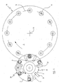
- the dies 11 are distributed equidistantly on a circumference 12 of the platform 1 coaxial to the axis 13 of rotation of the platform 1.
- a first auxiliary turntable 20 for withdrawing the sized portion, and comprising a number (m) of U-shaped hand-like elements 21 with their concavity facing in the direction of rotation of the turntable 20.
- a second auxiliary turntable 30 Coaxial to and below the platform 2 there is positioned the platform 3 of a second auxiliary turntable 30 carrying the cutting means, on the periphery of which there are equidistantly distributed a number (n) of blades 31.
- the turntables 20 and 30 rotate in the same direction.
- the number (n) of blades 31 is greater than the number of hand-like elements 21 by at least one, i.e. at least equal to (m+1).
- the ratio of the velocity of the platform 2 to the velocity of the platform 3 is equal to the ratio (m):(n), which is generally equal to (m):(m+1).
- each blade follows a hand-like element until, during one revolution of the platform 2, it becomes located exactly below it, whereas during the next revolution if follows the hand-like element which precedes it in the direction of rotation.
- the point at which the blades lie exactly below the hand-like elements is always the same and corresponds to the axis of the underlying nozzle 4 of the extruder.
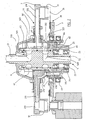
- Figure 2 is a section through the turntables 2 and 3, taken on two different radial planes.
- a fixed central structure 5 rigid with the machine bed, not shown, presents two axial channels 51 and 52 which do not mutually communicate, but terminate at their close-together ends with two radial channels 510 and 520 communicating with two circumferential channels 511 and 521, and are connected at their opposite ends to a suction environment.
- a bush 6 On the outside of the structure 5 there is mounted a bush 6 provided with a base flange 62 and two circumferential channels 61 and 610 positioned in front of the channels 511 and 521 of the structure 5. Two through holes 621 and 620 provided in the wall of the bush 6 connect the channels 61 and 610 to the outside.
- Gasket rings 63 seal the interior of said channels.
- the lower part of the structure 5 supports via the bearings 23 the turntable 20, which can rotate driven by means not shown, and comprises the platform 2.
- the platform 2 is clamped between an upper body 201 and a lower body 202; the lower body 202 is fixed, by means not shown, to the flange 62 of the bush 6 which itself is fixed to a plate 64 engaging the upper bearing 23; the plate 64 is fixed to a lower bush 65 of differential cross-sections which receives the body 202, the flange 62 and the plate 64 in that order starting from the top.
- the plate 2 peripherally carries six equidistant hand-like elements 21, each of which communicates with an upper cavity 210 into which two separate channels 211 and 212 extend.
- the channel 211 connects each hand-like element to a compressed air feed and is prolonged sideways and downwards to below the widened section of the bush 65 via channels 214 provided in the body 202, a hole in the flange 62 and a corresponding hole in the bush 65; a small bush 215 with seal gaskets is positioned in the corresponding holes of the body 202, the flange 62 and the bush 65.
- each of the cavities 210 there also arrives a channel 212 positioned to the side of the channel 211; in proximity to the centre of the plate 2 the channel 212 branches into two branches which open in front of the channels 61,510 and 610, 521 respectively, via the respective holes 621 and 521 provided in the bush 6.
- the bearing 32 rotatably supports the plate 3 of the turntable 30, on which seven equidistant blades 31 are distributed.
- the bearing 33 rotatably supports the bush 65 in a manner not shown.
- the cutting part of the blade is orientated in the direction of rotation of the plate 3, which rotates in the same direction as the plate 2, but at different velocity.
- the velocity of the plate 3 is equal to seven sixths of the velocity of the plate 2.
- the means which rotate the two plates are not shown in detail as they are of usual type, comprising an upper pulley fixed to the plate 3 and a lower pulley fixed to the bush 65, they being of suitably different diameters and connected by two separate drive belts to a single drive pulley connected synchronously to the means which rotate the turntable 1.
- the strip from which the sized portions are to be separated leaves continuously from the extrusion nozzle at a controlled velocity such as to obtain separation of portions of the desired size.
- the hand-like elements carried by the first auxiliary turntable pass below the extrusion nozzle at a distance therefrom such as to enable the blades of the second auxiliary turntable to pass.
- the velocity of the first auxiliary turntable and the velocity of the main turntable carrying the moulds are synchronized such that a hand-like element always lies over the cavity of a mould at the point of tangency of the circumferences of the two turntables carrying the hand-like elements and moulds respectively.
- the second auxiliary turntable carrying the blades is coaxial to the first auxiliary turntable and rotates in the same direction thereas.
- the velocity of the second auxiliary turntable is regulated relative to the velocity of the first auxiliary turntable in ratio to the number of blades and hand-like elements, such that a hand-like element and a blade pass simultaneously under the extrusion nozzle at different velocities.
- first and second turntable are coaxial and rotate in the same direction
- said turntables can be non-coaxial and rotate in opposite directions, regulating their velocities such that passage of the blades below the extrusion nozzle is always simultaneous with the presence of a hand-like element, and that each hand-like element always passes over the mould cavity without a blade therebetween.
- the sized portion collected by each hand-like element is then released into the mould cavity carried by the main turntable by virtue of an air jet which can flow from a conduit present in the said first auxiliary turntable, as in the illustrated example, or from a conduit present in a possible third auxiliary turntable.
Landscapes
- Engineering & Computer Science (AREA)
- Mechanical Engineering (AREA)
- Robotics (AREA)
- Processing And Handling Of Plastics And Other Materials For Molding In General (AREA)
- Casting Or Compression Moulding Of Plastics Or The Like (AREA)
- Extrusion Moulding Of Plastics Or The Like (AREA)
- Dry Formation Of Fiberboard And The Like (AREA)
- Devices For Indicating Variable Information By Combining Individual Elements (AREA)
- Electrical Discharge Machining, Electrochemical Machining, And Combined Machining (AREA)
- Signal Processing For Digital Recording And Reproducing (AREA)
- Refuse Collection And Transfer (AREA)
- Processing Of Solid Wastes (AREA)
- Separation, Recovery Or Treatment Of Waste Materials Containing Plastics (AREA)
- Devices For Post-Treatments, Processing, Supply, Discharge, And Other Processes (AREA)
Claims (14)
- Maschine zum Pressformen von Kunststoff, mit einem Hauptdrehtisch (10), der an seiner Peripherie äquidistant voneinander und von der Drehachse (13) des Drehtisches beabstandet eine Reihe von Hohlräumen oder Pressmatrizen (11) und jeweilige relativ zu den Pressmatrizen bewegliche Stempel trägt, einer Extrusionsdüse (4), und zumindest einem ersten Hilfsdrehtisch (20), der zwischen der Extrusionsdüse (4) und dem Hauptdrehtisch (11) angeordnet ist und Entnahmemittel (21) und zumindest ein Materialschneidemittel (31) trägt, um zu formende Materialabschnitte von der Extrusionsdüse (4) zu separieren und die Abschnitte in den Innenraum der Pressmatrizen (11) des Hauptdrehtisches (10) zu befördern, dadurch gekennzeichnet, dass der erste Hilfsdrehtisch (20) nur die Entnahmemittel (21) aufweist, wobei das zumindest eine Schneidemittel (31) von einem zweiten Hilfsdrehtisch (30) getragen ist, der um eine Achse parallel zur Drehachse des ersten Hilfsdrehtischs (20) dreht, derart, dass das zumindest eine Schneidemittel (31) eine Geschwindigkeit aufweist, die von der Geschwindigkeit der Entnahmemittel (21) vektoriell unterschiedlich ist, jedoch mit den Entnahmemitteln (21) in Korrespondenz mit der Extrusionsdüse (4) in Überlagerung kommt.
- Maschine nach Anspruch 1, dadurch gekennzeichnet, dass das zumindest eine Schneidemittel aus mechanischen, hydraulischen und thermischen Mitteln ausgewählt ist.
- Maschine nach Anspruch 1, dadurch gekennzeichnet, dass ein Kühlkreislauf innerhalb der Schneidemittel vorgesehen ist.
- Maschine nach Anspruch 1, dadurch gekennzeichnet, dass die Entnahmemittel ein greiferartiges Element (21) mit einem in der Bewegungsrichtung offenen U-Querschnitt und mit seiner Achse parallel zur Extrusionsdüse (4) sind.
- Maschine nach Anspruch 1, dadurch gekennzeichnet, dass das zumindest eine Schneidemittel eine gerade Klinge (31) ist.
- Maschine nach Anspruch 1, dadurch gekennzeichnet, dass der erste und der zweite Hilfsdrehtisch in derselben Richtung drehen.
- Maschine nach Anspruch 1, dadurch gekennzeichnet, dass der erste und der zweite Hilfsdrehtisch (20; 30) in entgegengesetzte Richtungen drehen.
- Maschine nach Anspruch 1, dadurch gekennzeichnet, dass der erste und der zweite Hilfsdrehtisch (20; 30) koaxial sind.
- Maschine nach Anspruch 1, dadurch gekennzeichnet, dass der erste und der zweite Hilfsdrehtisch um unterschiedliche Achsen drehen.
- Maschine nach Anspruch 9, dadurch gekennzeichnet, dass an dem zweiten Hilfsdrehtisch Klingen befestigt sind, die um ihre eigene Achse drehen, um so eine Planetenbewegung auszuführen.
- Maschine nach Anspruch 4, dadurch gekennzeichnet, dass die Extrusionsdüse (4) nach oben orientiert ist, wobei das greiferartige Element (21) oben geschlossen und unten offen ist.
- Maschine nach Anspruch 4, dadurch gekennzeichnet, dass die Extrusionsdüse nach unten orientiert ist, wobei das greiferartige Element nach oben und nach unten offen ist.
- Maschine nach Anspruch 4, gekennzeichnet durch einen dritten Hilfsdrehtisch, der pneumatische Mittel trägt, um den Übergang des Materialabschnitts von dem greiferartigen Element des ersten Hilfsdrehtischs zu den Formpressmatrizen zu erleichtern.
- Verfahren zum Pressformen von synthetischem Material, bei dem eine Maschine in Übereinstimmung mit einem der Ansprüche 1 bis 13 verwendet wird.
Priority Applications (2)
| Application Number | Priority Date | Filing Date | Title |
|---|---|---|---|
| EP10179065.7A EP2269792B1 (de) | 2003-01-31 | 2003-12-23 | Vorrichtung zum Abtrennen und Abtransportieren von einem abgemessenen Teil eines Materials in einer Anlage zur Herstellung von Artikeln durch Pressformung |
| EP10179240.6A EP2263844B1 (de) | 2003-01-31 | 2003-12-23 | Verfahren zum abtrennen und abtransportieren von einem abgemessenen teil eines materials in einer anlage zur herstellung von artikeln durch pressformung |
Applications Claiming Priority (3)
| Application Number | Priority Date | Filing Date | Title |
|---|---|---|---|
| IT000012A ITRE20030012A1 (it) | 2003-01-31 | 2003-01-31 | "dispositivo di separazione e trasporto della dose |
| ITRE20030012 | 2003-01-31 | ||
| PCT/EP2003/014887 WO2004067251A1 (en) | 2003-01-31 | 2003-12-23 | Device for separating and transporting a sized portion of material in a plant for forming articles by compression moulding |
Related Child Applications (2)
| Application Number | Title | Priority Date | Filing Date |
|---|---|---|---|
| EP10179240.6A Division EP2263844B1 (de) | 2003-01-31 | 2003-12-23 | Verfahren zum abtrennen und abtransportieren von einem abgemessenen teil eines materials in einer anlage zur herstellung von artikeln durch pressformung |
| EP10179065.7A Division EP2269792B1 (de) | 2003-01-31 | 2003-12-23 | Vorrichtung zum Abtrennen und Abtransportieren von einem abgemessenen Teil eines Materials in einer Anlage zur Herstellung von Artikeln durch Pressformung |
Publications (2)
| Publication Number | Publication Date |
|---|---|
| EP1590146A1 EP1590146A1 (de) | 2005-11-02 |
| EP1590146B1 true EP1590146B1 (de) | 2010-09-29 |
Family
ID=29267129
Family Applications (3)
| Application Number | Title | Priority Date | Filing Date |
|---|---|---|---|
| EP10179065.7A Expired - Lifetime EP2269792B1 (de) | 2003-01-31 | 2003-12-23 | Vorrichtung zum Abtrennen und Abtransportieren von einem abgemessenen Teil eines Materials in einer Anlage zur Herstellung von Artikeln durch Pressformung |
| EP03789419A Expired - Lifetime EP1590146B1 (de) | 2003-01-31 | 2003-12-23 | Vorrichtung zum abtrennen und abtransportieren von einem abgemessenen teil eines materials in einer anlage zur herstellung von artikeln durch pressformung und diese vorrichtung verwendendes verfahren |
| EP10179240.6A Expired - Lifetime EP2263844B1 (de) | 2003-01-31 | 2003-12-23 | Verfahren zum abtrennen und abtransportieren von einem abgemessenen teil eines materials in einer anlage zur herstellung von artikeln durch pressformung |
Family Applications Before (1)
| Application Number | Title | Priority Date | Filing Date |
|---|---|---|---|
| EP10179065.7A Expired - Lifetime EP2269792B1 (de) | 2003-01-31 | 2003-12-23 | Vorrichtung zum Abtrennen und Abtransportieren von einem abgemessenen Teil eines Materials in einer Anlage zur Herstellung von Artikeln durch Pressformung |
Family Applications After (1)
| Application Number | Title | Priority Date | Filing Date |
|---|---|---|---|
| EP10179240.6A Expired - Lifetime EP2263844B1 (de) | 2003-01-31 | 2003-12-23 | Verfahren zum abtrennen und abtransportieren von einem abgemessenen teil eines materials in einer anlage zur herstellung von artikeln durch pressformung |
Country Status (14)
| Country | Link |
|---|---|
| US (2) | US7427195B2 (de) |
| EP (3) | EP2269792B1 (de) |
| JP (1) | JP4455346B2 (de) |
| CN (1) | CN100406222C (de) |
| AT (1) | ATE482807T1 (de) |
| AU (1) | AU2003294005B2 (de) |
| BR (2) | BRPI0318075B8 (de) |
| CA (1) | CA2514335C (de) |
| DE (1) | DE60334410D1 (de) |
| ES (1) | ES2354751T3 (de) |
| IT (1) | ITRE20030012A1 (de) |
| MX (1) | MXPA05008139A (de) |
| RU (1) | RU2345887C2 (de) |
| WO (1) | WO2004067251A1 (de) |
Families Citing this family (8)
| Publication number | Priority date | Publication date | Assignee | Title |
|---|---|---|---|---|
| BRPI0510081A (pt) * | 2004-04-23 | 2007-10-16 | Sacmi | aparelhos e métodos para transferir material plástico para uma máquina de moldagem por compressão |
| ITMO20050223A1 (it) | 2005-09-07 | 2007-03-08 | Sacmi | Apparati e metodi per prcessare dosi di materiale scorrevole |
| JP4725362B2 (ja) | 2006-02-28 | 2011-07-13 | 東洋製罐株式会社 | 溶融樹脂供給方法及び溶融樹脂供給装置 |
| US7357631B2 (en) * | 2006-05-10 | 2008-04-15 | Owens-Illinois Closures, Inc. | Apparatus for placing mold charges in a compression molding machine |
| WO2008114579A1 (ja) * | 2007-03-22 | 2008-09-25 | Toyo Seikan Kaisha, Ltd. | 圧縮成形金型 |
| AU2011241357B2 (en) * | 2010-04-14 | 2014-12-18 | Lg Electronics Inc. | Method for setting a search space for a relay node in a wireless communication system and apparatus for same |
| CN108941910A (zh) * | 2018-10-15 | 2018-12-07 | 广东正业科技股份有限公司 | 一种激光焊接设备 |
| CN112046030A (zh) * | 2020-08-26 | 2020-12-08 | 安庆柯麦机电科技有限公司 | 通讯设备箱体成型系统 |
Family Cites Families (17)
| Publication number | Priority date | Publication date | Assignee | Title |
|---|---|---|---|---|
| US3025564A (en) * | 1957-11-01 | 1962-03-20 | Lonza Electric & Chem Works | Apparatus for producing small bodies from a plastic mass |
| US3827843A (en) * | 1972-01-26 | 1974-08-06 | Sycamore Mfg Co Inc | Apparatus for lining bottle crowns with thermoplastic material |
| US3782329A (en) * | 1972-02-09 | 1974-01-01 | Gros Ite Industries | Apparatus for dispensing plastic material or the like |
| US3955605A (en) * | 1975-02-27 | 1976-05-11 | H-C Industries, Inc. | Apparatus and method for supplying a metered charge at any feed rate |
| US4277431A (en) * | 1977-11-30 | 1981-07-07 | H-C Industries, Inc. | Method of dispensing metered charges of material |
| JPS559860A (en) * | 1978-07-10 | 1980-01-24 | Japan Crown Cork Co Ltd | Cap shellsigma interior lining material distributing device |
| JPS60245517A (ja) * | 1984-05-22 | 1985-12-05 | Toyo Seikan Kaisha Ltd | 圧縮成形装置 |
| FR2636210B1 (fr) * | 1988-09-13 | 1993-04-09 | Kaufler Sa | Dispositif pour produire en continu des morceaux de viande sensiblement parallelepipediques |
| JP2929018B2 (ja) * | 1989-12-07 | 1999-08-03 | 日本クラウンコルク株式会社 | 圧縮成形装置 |
| US5370519A (en) * | 1993-01-26 | 1994-12-06 | Zapata Technologies, Inc. | Apparatus for cutting and dispensing cap lining material |
| US5386971A (en) * | 1993-07-22 | 1995-02-07 | Owens-Illinois Closure Inc. | Plastic pellet delivery system and method of use |
| ITBO940242A1 (it) * | 1994-05-23 | 1995-11-23 | Sacmi | Apparecchiatura per lo stampaggio a pressione di articoli in materiale plastico, come capsule per la chiusura di contenitori e simili. |
| US5672364A (en) * | 1994-07-07 | 1997-09-30 | Sankyo Seisakusho Co. & Eisai Co., Ltd. | Apparatus for manufacturing tablets |
| US5603964A (en) * | 1994-10-07 | 1997-02-18 | Owens-Illinois Closure Inc. | Apparatus for cutting and delivering plastic gobs |
| US6368094B1 (en) * | 1999-11-22 | 2002-04-09 | Alcoa Closure Systems International | Multi-path compression molding apparatus |
| US6619946B1 (en) * | 2000-07-20 | 2003-09-16 | Delaware Capitol Formation, Inc. | Apparatus for trimming and performing a second operation on plastic containers |
| ITBO20020683A1 (it) * | 2002-10-31 | 2004-05-01 | Sacmi | Dispositivo per il prelievo di dosi di materiale plastico da un estrusore |
-
2003
- 2003-01-31 IT IT000012A patent/ITRE20030012A1/it unknown
- 2003-12-23 EP EP10179065.7A patent/EP2269792B1/de not_active Expired - Lifetime
- 2003-12-23 DE DE60334410T patent/DE60334410D1/de not_active Expired - Lifetime
- 2003-12-23 ES ES03789419T patent/ES2354751T3/es not_active Expired - Lifetime
- 2003-12-23 BR BRPI0318075A patent/BRPI0318075B8/pt unknown
- 2003-12-23 JP JP2004567332A patent/JP4455346B2/ja not_active Expired - Lifetime
- 2003-12-23 AT AT03789419T patent/ATE482807T1/de active
- 2003-12-23 EP EP03789419A patent/EP1590146B1/de not_active Expired - Lifetime
- 2003-12-23 BR BRPI0318075-1A patent/BR0318075B1/pt active IP Right Grant
- 2003-12-23 MX MXPA05008139A patent/MXPA05008139A/es active IP Right Grant
- 2003-12-23 CA CA2514335A patent/CA2514335C/en not_active Expired - Lifetime
- 2003-12-23 WO PCT/EP2003/014887 patent/WO2004067251A1/en active Application Filing
- 2003-12-23 AU AU2003294005A patent/AU2003294005B2/en not_active Ceased
- 2003-12-23 EP EP10179240.6A patent/EP2263844B1/de not_active Expired - Lifetime
- 2003-12-23 RU RU2005127338/12A patent/RU2345887C2/ru active
- 2003-12-23 CN CNB2003801093573A patent/CN100406222C/zh not_active Expired - Lifetime
-
2004
- 2004-01-07 US US10/752,087 patent/US7427195B2/en active Active
-
2008
- 2008-09-10 US US12/208,042 patent/US7695659B2/en not_active Expired - Lifetime
Also Published As
| Publication number | Publication date |
|---|---|
| CA2514335C (en) | 2011-08-23 |
| BRPI0318075A (de) | 2005-12-20 |
| EP2269792B1 (de) | 2014-07-30 |
| US7695659B2 (en) | 2010-04-13 |
| ATE482807T1 (de) | 2010-10-15 |
| EP2263844A3 (de) | 2013-06-12 |
| BR0318075A (pt) | 2005-12-20 |
| DE60334410D1 (de) | 2010-11-11 |
| BRPI0318075B1 (de) | 2015-02-18 |
| BRPI0318075B8 (pt) | 2022-07-12 |
| AU2003294005A1 (en) | 2004-08-23 |
| EP2269792A3 (de) | 2013-06-12 |
| EP1590146A1 (de) | 2005-11-02 |
| BR0318075B1 (pt) | 2015-02-18 |
| EP2269792A2 (de) | 2011-01-05 |
| CA2514335A1 (en) | 2004-08-12 |
| RU2005127338A (ru) | 2006-05-10 |
| US20090008814A1 (en) | 2009-01-08 |
| JP4455346B2 (ja) | 2010-04-21 |
| MXPA05008139A (es) | 2006-02-17 |
| EP2263844B1 (de) | 2015-10-28 |
| US20040212128A1 (en) | 2004-10-28 |
| CN100406222C (zh) | 2008-07-30 |
| ITRE20030012A0 (it) | 2003-01-31 |
| AU2003294005B2 (en) | 2009-03-12 |
| EP2263844A2 (de) | 2010-12-22 |
| US7427195B2 (en) | 2008-09-23 |
| WO2004067251A1 (en) | 2004-08-12 |
| CN1744975A (zh) | 2006-03-08 |
| ES2354751T3 (es) | 2011-03-17 |
| RU2345887C2 (ru) | 2009-02-10 |
| JP2006513882A (ja) | 2006-04-27 |
| ITRE20030012A1 (it) | 2004-08-01 |
Similar Documents
| Publication | Publication Date | Title |
|---|---|---|
| US7695659B2 (en) | Method for separating and transporting a sized portion of material in a plant for forming articles by compression moulding | |
| CA1169215A (en) | Continuous rotary thermo-forming systems and apparatus of the pressure assist, plug assist and match mold type | |
| JP3770907B2 (ja) | 容器等を閉じるキャップ等のプラスティック物品の圧力成形装置 | |
| US5603964A (en) | Apparatus for cutting and delivering plastic gobs | |
| US6368094B1 (en) | Multi-path compression molding apparatus | |
| ES8607100A1 (es) | Un aparato de moldeo por compresion | |
| US20070290395A1 (en) | Bottle Trimmer and Method | |
| EP1578577B1 (de) | Vorrichtung zur entnahme von materialproben aus einem kunststoffextruder | |
| US3333298A (en) | Granulating machines | |
| US20040018263A1 (en) | Apparatus useful for continuous forming of thermoplastic material and method for use thereof | |
| CA2002228A1 (en) | Compression molding apparatus | |
| EP1896238B1 (de) | Formbefüllungsvorrichtung | |
| CN219857808U (zh) | 一种方便粉丝生产用的理饼传输装置 | |
| CN220236026U (zh) | 垂直挤出成型机 | |
| US3695804A (en) | Sheet molding apparatus including means for removing molded articles from the sheet material | |
| CA2190949C (en) | Apparatus for pressure-molding items made of plastics | |
| CN201086377Y (zh) | 滚压式塑料成型机 | |
| CN117140825A (zh) | 物料运输及组装系统 | |
| EP1825972A2 (de) | Scheidvorrichtung einer Vorrichtung zur Herstellung von Kunststoffverschlüssen | |
| ES8607106A1 (es) | Perfeccionamientos en las maquinas para fabricar cuerpos huecos de material termoplastico |
Legal Events
| Date | Code | Title | Description |
|---|---|---|---|
| PUAI | Public reference made under article 153(3) epc to a published international application that has entered the european phase |
Free format text: ORIGINAL CODE: 0009012 |
|
| AK | Designated contracting states |
Kind code of ref document: A1 Designated state(s): AT BE BG CH CY CZ DE DK EE ES FI FR GB GR HU IE IT LI LU MC NL PT RO SE SI SK TR |
|
| AX | Request for extension of the european patent |
Extension state: AL LT LV MK |
|
| 17P | Request for examination filed |
Effective date: 20050812 |
|
| DAX | Request for extension of the european patent (deleted) | ||
| 17Q | First examination report despatched |
Effective date: 20081113 |
|
| R17C | First examination report despatched (corrected) |
Effective date: 20081113 |
|
| GRAP | Despatch of communication of intention to grant a patent |
Free format text: ORIGINAL CODE: EPIDOSNIGR1 |
|
| RTI1 | Title (correction) |
Free format text: DEVICE FOR SEPARATING AND TRANSPORTING A SIZED PORTION OF MATERIAL IN A PLANT FOR FORMING ARTICLES BY COMPRESSION MOULDING AND METHOD USING THIS DEVICE |
|
| GRAS | Grant fee paid |
Free format text: ORIGINAL CODE: EPIDOSNIGR3 |
|
| GRAA | (expected) grant |
Free format text: ORIGINAL CODE: 0009210 |
|
| AK | Designated contracting states |
Kind code of ref document: B1 Designated state(s): AT BE BG CH CY CZ DE DK EE ES FI FR GB GR HU IE IT LI LU MC NL PT RO SE SI SK TR |
|
| REG | Reference to a national code |
Ref country code: GB Ref legal event code: FG4D |
|
| REG | Reference to a national code |
Ref country code: CH Ref legal event code: EP |
|
| REG | Reference to a national code |
Ref country code: IE Ref legal event code: FG4D |
|
| REF | Corresponds to: |
Ref document number: 60334410 Country of ref document: DE Date of ref document: 20101111 Kind code of ref document: P |
|
| PG25 | Lapsed in a contracting state [announced via postgrant information from national office to epo] |
Ref country code: FI Free format text: LAPSE BECAUSE OF FAILURE TO SUBMIT A TRANSLATION OF THE DESCRIPTION OR TO PAY THE FEE WITHIN THE PRESCRIBED TIME-LIMIT Effective date: 20100929 |
|
| REG | Reference to a national code |
Ref country code: NL Ref legal event code: VDEP Effective date: 20100929 |
|
| PG25 | Lapsed in a contracting state [announced via postgrant information from national office to epo] |
Ref country code: SI Free format text: LAPSE BECAUSE OF FAILURE TO SUBMIT A TRANSLATION OF THE DESCRIPTION OR TO PAY THE FEE WITHIN THE PRESCRIBED TIME-LIMIT Effective date: 20100929 |
|
| REG | Reference to a national code |
Ref country code: ES Ref legal event code: FG2A Effective date: 20110307 |
|
| PG25 | Lapsed in a contracting state [announced via postgrant information from national office to epo] |
Ref country code: SE Free format text: LAPSE BECAUSE OF FAILURE TO SUBMIT A TRANSLATION OF THE DESCRIPTION OR TO PAY THE FEE WITHIN THE PRESCRIBED TIME-LIMIT Effective date: 20100929 Ref country code: GR Free format text: LAPSE BECAUSE OF FAILURE TO SUBMIT A TRANSLATION OF THE DESCRIPTION OR TO PAY THE FEE WITHIN THE PRESCRIBED TIME-LIMIT Effective date: 20101230 |
|
| PG25 | Lapsed in a contracting state [announced via postgrant information from national office to epo] |
Ref country code: EE Free format text: LAPSE BECAUSE OF FAILURE TO SUBMIT A TRANSLATION OF THE DESCRIPTION OR TO PAY THE FEE WITHIN THE PRESCRIBED TIME-LIMIT Effective date: 20100929 Ref country code: PT Free format text: LAPSE BECAUSE OF FAILURE TO SUBMIT A TRANSLATION OF THE DESCRIPTION OR TO PAY THE FEE WITHIN THE PRESCRIBED TIME-LIMIT Effective date: 20110131 Ref country code: CZ Free format text: LAPSE BECAUSE OF FAILURE TO SUBMIT A TRANSLATION OF THE DESCRIPTION OR TO PAY THE FEE WITHIN THE PRESCRIBED TIME-LIMIT Effective date: 20100929 Ref country code: RO Free format text: LAPSE BECAUSE OF FAILURE TO SUBMIT A TRANSLATION OF THE DESCRIPTION OR TO PAY THE FEE WITHIN THE PRESCRIBED TIME-LIMIT Effective date: 20100929 Ref country code: SK Free format text: LAPSE BECAUSE OF FAILURE TO SUBMIT A TRANSLATION OF THE DESCRIPTION OR TO PAY THE FEE WITHIN THE PRESCRIBED TIME-LIMIT Effective date: 20100929 Ref country code: NL Free format text: LAPSE BECAUSE OF FAILURE TO SUBMIT A TRANSLATION OF THE DESCRIPTION OR TO PAY THE FEE WITHIN THE PRESCRIBED TIME-LIMIT Effective date: 20100929 |
|
| PG25 | Lapsed in a contracting state [announced via postgrant information from national office to epo] |
Ref country code: BE Free format text: LAPSE BECAUSE OF FAILURE TO SUBMIT A TRANSLATION OF THE DESCRIPTION OR TO PAY THE FEE WITHIN THE PRESCRIBED TIME-LIMIT Effective date: 20100929 |
|
| PG25 | Lapsed in a contracting state [announced via postgrant information from national office to epo] |
Ref country code: MC Free format text: LAPSE BECAUSE OF NON-PAYMENT OF DUE FEES Effective date: 20101231 |
|
| REG | Reference to a national code |
Ref country code: CH Ref legal event code: PL |
|
| PLBE | No opposition filed within time limit |
Free format text: ORIGINAL CODE: 0009261 |
|
| STAA | Information on the status of an ep patent application or granted ep patent |
Free format text: STATUS: NO OPPOSITION FILED WITHIN TIME LIMIT |
|
| PG25 | Lapsed in a contracting state [announced via postgrant information from national office to epo] |
Ref country code: DK Free format text: LAPSE BECAUSE OF FAILURE TO SUBMIT A TRANSLATION OF THE DESCRIPTION OR TO PAY THE FEE WITHIN THE PRESCRIBED TIME-LIMIT Effective date: 20100929 |
|
| 26N | No opposition filed |
Effective date: 20110630 |
|
| REG | Reference to a national code |
Ref country code: DE Ref legal event code: R097 Ref document number: 60334410 Country of ref document: DE Effective date: 20110630 |
|
| PG25 | Lapsed in a contracting state [announced via postgrant information from national office to epo] |
Ref country code: IE Free format text: LAPSE BECAUSE OF NON-PAYMENT OF DUE FEES Effective date: 20101223 Ref country code: CH Free format text: LAPSE BECAUSE OF NON-PAYMENT OF DUE FEES Effective date: 20101231 Ref country code: LI Free format text: LAPSE BECAUSE OF NON-PAYMENT OF DUE FEES Effective date: 20101231 |
|
| PG25 | Lapsed in a contracting state [announced via postgrant information from national office to epo] |
Ref country code: CY Free format text: LAPSE BECAUSE OF FAILURE TO SUBMIT A TRANSLATION OF THE DESCRIPTION OR TO PAY THE FEE WITHIN THE PRESCRIBED TIME-LIMIT Effective date: 20100929 |
|
| PG25 | Lapsed in a contracting state [announced via postgrant information from national office to epo] |
Ref country code: HU Free format text: LAPSE BECAUSE OF FAILURE TO SUBMIT A TRANSLATION OF THE DESCRIPTION OR TO PAY THE FEE WITHIN THE PRESCRIBED TIME-LIMIT Effective date: 20110330 Ref country code: LU Free format text: LAPSE BECAUSE OF NON-PAYMENT OF DUE FEES Effective date: 20101223 Ref country code: BG Free format text: LAPSE BECAUSE OF FAILURE TO SUBMIT A TRANSLATION OF THE DESCRIPTION OR TO PAY THE FEE WITHIN THE PRESCRIBED TIME-LIMIT Effective date: 20100929 |
|
| PG25 | Lapsed in a contracting state [announced via postgrant information from national office to epo] |
Ref country code: TR Free format text: LAPSE BECAUSE OF FAILURE TO SUBMIT A TRANSLATION OF THE DESCRIPTION OR TO PAY THE FEE WITHIN THE PRESCRIBED TIME-LIMIT Effective date: 20100929 |
|
| PGFP | Annual fee paid to national office [announced via postgrant information from national office to epo] |
Ref country code: ES Payment date: 20121205 Year of fee payment: 10 Ref country code: GB Payment date: 20121122 Year of fee payment: 10 |
|
| PG25 | Lapsed in a contracting state [announced via postgrant information from national office to epo] |
Ref country code: BG Free format text: LAPSE BECAUSE OF FAILURE TO SUBMIT A TRANSLATION OF THE DESCRIPTION OR TO PAY THE FEE WITHIN THE PRESCRIBED TIME-LIMIT Effective date: 20101229 |
|
| GBPC | Gb: european patent ceased through non-payment of renewal fee |
Effective date: 20131223 |
|
| PG25 | Lapsed in a contracting state [announced via postgrant information from national office to epo] |
Ref country code: GB Free format text: LAPSE BECAUSE OF NON-PAYMENT OF DUE FEES Effective date: 20131223 |
|
| REG | Reference to a national code |
Ref country code: ES Ref legal event code: FD2A Effective date: 20150330 |
|
| PG25 | Lapsed in a contracting state [announced via postgrant information from national office to epo] |
Ref country code: ES Free format text: LAPSE BECAUSE OF NON-PAYMENT OF DUE FEES Effective date: 20131224 |
|
| REG | Reference to a national code |
Ref country code: FR Ref legal event code: PLFP Year of fee payment: 13 |
|
| REG | Reference to a national code |
Ref country code: FR Ref legal event code: PLFP Year of fee payment: 14 |
|
| REG | Reference to a national code |
Ref country code: FR Ref legal event code: PLFP Year of fee payment: 15 |
|
| PGFP | Annual fee paid to national office [announced via postgrant information from national office to epo] |
Ref country code: IT Payment date: 20221122 Year of fee payment: 20 Ref country code: FR Payment date: 20221123 Year of fee payment: 20 Ref country code: DE Payment date: 20221122 Year of fee payment: 20 Ref country code: AT Payment date: 20221123 Year of fee payment: 20 |
|
| P01 | Opt-out of the competence of the unified patent court (upc) registered |
Effective date: 20230529 |
|
| REG | Reference to a national code |
Ref country code: DE Ref legal event code: R071 Ref document number: 60334410 Country of ref document: DE |
|
| REG | Reference to a national code |
Ref country code: AT Ref legal event code: MK07 Ref document number: 482807 Country of ref document: AT Kind code of ref document: T Effective date: 20231223 |