EP1590136B1 - Razor head having skin controlling means - Google Patents
Razor head having skin controlling means Download PDFInfo
- Publication number
- EP1590136B1 EP1590136B1 EP04707775A EP04707775A EP1590136B1 EP 1590136 B1 EP1590136 B1 EP 1590136B1 EP 04707775 A EP04707775 A EP 04707775A EP 04707775 A EP04707775 A EP 04707775A EP 1590136 B1 EP1590136 B1 EP 1590136B1
- Authority
- EP
- European Patent Office
- Prior art keywords
- blade
- cutting edge
- razor head
- guard elements
- set forth
- Prior art date
- Legal status (The legal status is an assumption and is not a legal conclusion. Google has not performed a legal analysis and makes no representation as to the accuracy of the status listed.)
- Expired - Lifetime
Links
- 125000006850 spacer group Chemical group 0.000 claims description 15
- 238000003491 array Methods 0.000 claims 2
- 238000010276 construction Methods 0.000 description 4
- 238000004519 manufacturing process Methods 0.000 description 3
- 239000000463 material Substances 0.000 description 2
- 230000001419 dependent effect Effects 0.000 description 1
- 230000035807 sensation Effects 0.000 description 1
Images

Classifications
-
- B—PERFORMING OPERATIONS; TRANSPORTING
- B26—HAND CUTTING TOOLS; CUTTING; SEVERING
- B26B—HAND-HELD CUTTING TOOLS NOT OTHERWISE PROVIDED FOR
- B26B21/00—Razors of the open or knife type; Safety razors or other shaving implements of the planing type; Hair-trimming devices involving a razor-blade; Equipment therefor
- B26B21/40—Details or accessories
- B26B21/4012—Housing details, e.g. for cartridges
- B26B21/4018—Guard elements
-
- B—PERFORMING OPERATIONS; TRANSPORTING
- B26—HAND CUTTING TOOLS; CUTTING; SEVERING
- B26B—HAND-HELD CUTTING TOOLS NOT OTHERWISE PROVIDED FOR
- B26B21/00—Razors of the open or knife type; Safety razors or other shaving implements of the planing type; Hair-trimming devices involving a razor-blade; Equipment therefor
- B26B21/08—Razors of the open or knife type; Safety razors or other shaving implements of the planing type; Hair-trimming devices involving a razor-blade; Equipment therefor involving changeable blades
- B26B21/14—Safety razors with one or more blades arranged transversely to the handle
- B26B21/22—Safety razors with one or more blades arranged transversely to the handle involving several blades to be used simultaneously
- B26B21/222—Safety razors with one or more blades arranged transversely to the handle involving several blades to be used simultaneously with the blades moulded into, or attached to, a changeable unit
Definitions
- This invention relates in general to razor heads and deals more particularly with improvements in razor heads which include means for controlling skin flow to limit the degree of blade edge exposure and thereby reduce the probability of nicks and cuts.
- Current shaving systems for providing such control, and particularly those of the multiblade type generally employ a wire wrapped cartridge for limiting the degree of closeness of a shave.
- Such systems add parts to a razor head or blade cartridge and generally require additional steps in the manufacturing process to attain the desired skin control feature, all of which add substantially to the cost of producing a razor.
- US-A-5,359,774 discloses a razor head having a plastic body in which is disposed a razor blade unit.
- the plastic body has a top cover and a front guardbar that define surface points for engaging the skin of a user. At least one of the guardbar and the top cover are provided with at least two comb-like projections.
- a razor head comprises the features of claim 1 with the dependent claims defining individual embodiments of the invention.
- the razor head according to the invention has a blade seat member which includes a seat body, a seat blade mounted in fixed position on the blade seat member and having an unobstructed cutting edge spaced from the seat body, and a guard assembly for controlling skin flow and limiting the degree of blade cutting edge exposure to skin being shaved and which includes a plurality of discrete space apart guard elements carried by and projecting in cantilever position from the seat body below and in spaced relation to the seat blade.
- the guard elements have free end portions disposed at spaced intervals along and forward of the blade cutting edge which is unobstructed along its entire cutting edge. The free end portions are configured for smooth engagement with the skin.
- the razor head of the present invention may take various forms and may, for example, comprise the head portion of a unitary disposable razor of the type having a single blade.
- a detachable multiple blade cartridge indicated generally by the reference numeral 10.
- the illustrated blade cartridge 10 essentially comprises a pair of blades which includes a first or seat blade 12, which has a generally rectilinear forwardly facing cutting edge 14, and a second blade 16, which includes a forwardly facing cutting edge indicated at 18.
- the seat blade 12 is mounted in fixed position on a blade support member or blade seat 20.
- the second blade 16 is supported on and maintained in spaced relation to the seat blade 12 by another blade support or spacing member 22 sandwiched between the blades.
- the cartridge 10 further includes a blade cap 24 which overlies the second or upper blade 16, substantially as shown in Fig. 1 and 3.
- a guard assembly indicated generally at 26 and which include a plurality of discreet spaced apart guard elements 28,28 is carried by the blade seat 20.
- a guard assembly 26' which includes a plurality of guard elements 28', 28' is carried by the spacing member or spacer 22.
- the guard elements 28', 28' are or may be substantially identical to the guard elements 28, 28 carried by the blade seat 12.
- the blade seat 20 is preferably molded from a durable plastic material and comprises a unitary structure which includes a seat body 30 and the guard element 28,28 which are integrally formed thereon.
- the seat body 30 has a substantially planar upwardly facing seating surface 31 upon which the seat blade 12 is mounted with its longitudinally extending cutting edge 14 spaced forwardly of the seat body 30, as best shown in Fig. 3.
- the guard elements 28,28 project forwardly from the seat body 30 in cantilever position and parallel spaced apart relation to each other below and in spaced relation to the seat blade 12.
- the guard elements 28,28 have enlarged free end portions 32,32 disposed at spaced intervals along and forward of the cutting edge 14 and are configured or shaped for smooth engagement with the skin to be shaved.
- the enlarged free end portions 32,32 are parti- cylindrical, that is substantially cylindrical except in regions of connection to the cantilever beams which support them on the seat body.
- the parti-cylindrical free end portions 32,32 are arranged at longitudinally spaced apart intervals along the length of the blade 12 and in coaxial alignment with each other and axially parallel alignment with the blade cutting edge 14 as best shown in Figs. 1 and 2.
- the construction of the spacer 22 is similar to that of the blade seat 20.
- the spacer 22 is preferably molded from a durable plastic material and has a generally rectangular body portion indicated at 34.
- the guard elements 28', 28' are integrally formed on the spacer 22 and project forwardly in cantilever positions from the body portion 34.
- Each guard element 28' has an enlarged free end portion 32' which is preferably parti-cylindrical, as previously described with reference to the corresponding guard elements 28,28 on the blade seat.
- the enlarged parti-cylindrical end portions 32', 32' are coaxially aligned and arranged in axially parallel alignment with the cutting edge 18 on the second blade 16. Referring to Fig.
- the guard elements associated with the blade cutting edges and which control skin flow and limit the degree of blade cutting edge exposure to the skin may be arranged in various ways relative to each other and to the cutting edges of the blades. As shown in Fig. 1 and 2, the blade guard elements 28,28 and 28', 28' are arranged in a staggered pattern relative to each other along the cutting edges. More specifically, the guard elements 28,28 and 28', 28' are arranged in alternate series at opposite sides of an imaginary median line disposed between and extending in parallel relation to the blade edges 14 and 18. However, other guard element arrangements are possible and are contemplated within the scope of the present invention.
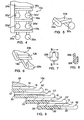
- FIG. 10a another blade cartridge embodying the invention is illustrated and indicated generally by the reference numeral 10a.
- the blade cartridge 10a is similar in most respects to the previously described blade cartridge 10 but has three blades which include a seat blade 12a and two other blades 16a, 16a.
- the blade cartridge 10a further differs from the blade cartridge 10 in the construction and arrangement of its guard elements. More specifically, the guard elements which comprise the blade cartridge 10a have parti-spherical free end portions indicated at 32a, 32a, 32a', 32a', and 32a", 32a".
- each parti- spherical element 32a is transversely aligned with both a parti-spherical element 32a' and another such element 32a" relative to the longitudinally extending cutting edge 14a on the seat blade 12a, as shown in Fig. 4.
- FIGs. 6-8 there is shown still another form of razor head or blade cartridge 10b which has a single blade or seat blade 12b supported on a blade seat which carries a plurality of smoothly configured guard elements 32b (one shown).
- Each guard element 32b has a generally wedge shaped configuration and is characterized by sidewalls which converge toward a tip, as shown in Fig. 6 wherein the sidewalls of the enlarged free end portion 32b converge toward the cutting edge 14b of a seat blade 12b.
- Fig. 9 there is shown yet another embodiment of the invention indicated generally by the reference numeral 10c.
- the razor head 10c is substantially identical in most respects to the razor head 10 shown in Figs. 1-3 of the drawings, but differs from the razor head 10 in that it has four blades.
- Parts of the razor head 10c which are substantially identical to parts of the razor head 10 bear the same reference numerals as those of the razor head 10. Consequently, these identical parts will not be hereinafter further described.
- FIG. 10 Another blade cartridge embodying the present invention and designated generally at 10d is shown in Fig. 10.
- the blade cartridge 10d is substantially identical in many respects to razor head 10 illustrated in Figs. 1-3 of the drawings. Parts of the blade cartridge 10d substantially identical to previously described parts of the razor head 10, shown in Figs. 1-3, bear the same reference numerals as the previously described parts.
- the razor cartridge 10d differs from the previously described cartridge 10 in that it has a first in-line array of discreet spaced apart guard elements, indicated generally at 35, associated with the seat blade 12, and which include parti-spherical free end portions indicated at 36.
- the guard elements, which comprise the first array 35 have a variable pitch, indicated by the letters P 1 through P 4 , the pitch being the distance between the center lines of adjacent guard elements.
- a second in-line array of spaced apart guard elements includes free end portions 40.
- Each end portion 40 has a generally teardrop configuration.
- the guard elements which comprise the first in-line array 35 have differently shaped free end portions than those which form the second in-line array 38.
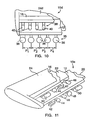
- FIG. 11 another razor head or detachable cartridge embodying the present invention is shown in Fig. 11 and indicated generally by the reference numeral 10e.
- the cartridge 10e includes a first or seat blade 12 carried by a blade seat 20 and a second blade 16 supported on a spacing member 22 sandwiched between the first and second blades.
- a blade cap 24 overlies the upper blade 16 and forms the end walls of the blade cartridge.
- the blade cartridge 10e differs from the previously described razor head or cartridge 10 in the construction and the arrangement of its guard elements. More specifically, the blade seat 20 carries an in-line array of guard elements having free end portions which differ in shape from each other from one end of the blade cartridge to the other end of the blade cartridge.
- the fragmentary view of the blade cartridge 10e shown in Fig. 11 shows guard elements having free end portions indicated at 42,44, 46,48 and 50, which are carried by blade seat 20.
- the free end portion 42 is shaped generally like a smooth segment of a disk, whereas the next guard element free end portion 44 has a spherical configuration.
- the element 46 has a generally teardrop form.
- the next successive element in the series includes a free end portion having a knob shape and indicated at 48.
- the series of guard elements is further characterized by the parti-cylindrical free end portion 50.
- Further guard elements (not shown), which complete the series of guard elements associated with the seat blade 12 are each of a different shape, so that the shape of the guard elements in the series change successively from one end of the blade cartridge to the other.
- Another array of guard elements is carried by the separating member 22 and may include guard elements like some, if not all, of those carried by the blade seat 20 or, if desired, each guard element in the series may have an end portion shaped like no other guard element end portion on the razor head or blade cartridge 10e.
- effective skin control may be achieved by employing diverse skin engaging guard elements which also provide pleasing skin sensation.
- each of the differing smoothly configured guard element free end portions hereinbefore described will produce a somewhat different skin flow reaction to shaving pressure
- the characteristics of any of the aforedescribed razor heads including the configuration of the free end portions, the spacing or pitch between adjacent guard elements, the thickness of the spacers, the arrangement of the guard elements relative to each other and/or the spacing between the enlarged end portions of the guard elements and the unobstructed cutting edges of the blades variations in skin flow and blade exposure to skin to be shaved may be attained, whereby a razor may be produced which is particularly suited to the skin condition of a user.
Landscapes
- Life Sciences & Earth Sciences (AREA)
- Forests & Forestry (AREA)
- Engineering & Computer Science (AREA)
- Mechanical Engineering (AREA)
- Dry Shavers And Clippers (AREA)
- Golf Clubs (AREA)
- Surgical Instruments (AREA)
Applications Claiming Priority (3)
| Application Number | Priority Date | Filing Date | Title |
|---|---|---|---|
| US44478003P | 2003-02-04 | 2003-02-04 | |
| US444780P | 2003-02-04 | ||
| PCT/US2004/003032 WO2004069496A1 (en) | 2003-02-04 | 2004-02-03 | Razor head having skin controlling means |
Publications (2)
| Publication Number | Publication Date |
|---|---|
| EP1590136A1 EP1590136A1 (en) | 2005-11-02 |
| EP1590136B1 true EP1590136B1 (en) | 2007-10-03 |
Family
ID=32850930
Family Applications (1)
| Application Number | Title | Priority Date | Filing Date |
|---|---|---|---|
| EP04707775A Expired - Lifetime EP1590136B1 (en) | 2003-02-04 | 2004-02-03 | Razor head having skin controlling means |
Country Status (7)
| Country | Link |
|---|---|
| US (1) | US7111401B2 (enExample) |
| EP (1) | EP1590136B1 (enExample) |
| JP (1) | JP2006516464A (enExample) |
| AT (1) | ATE374678T1 (enExample) |
| AU (1) | AU2004209545B2 (enExample) |
| DE (1) | DE602004009289T2 (enExample) |
| WO (1) | WO2004069496A1 (enExample) |
Families Citing this family (35)
| Publication number | Priority date | Publication date | Assignee | Title |
|---|---|---|---|---|
| US7272991B2 (en) * | 2004-02-09 | 2007-09-25 | The Gillette Company | Shaving razors, and blade subassemblies therefor and methods of manufacture |
| US20100218381A1 (en) * | 2005-06-10 | 2010-09-02 | Follo Thomas A | Inter-Blade Guard and Method For Manufacturing Same |
| US7681314B2 (en) * | 2005-06-10 | 2010-03-23 | Eveready Battery Company Inc. | Inter-blade guard and method for manufacturing same |
| JP4977374B2 (ja) * | 2006-02-14 | 2012-07-18 | 株式会社貝印刃物開発センター | 剃刀 |
| JP4950507B2 (ja) * | 2006-02-14 | 2012-06-13 | 株式会社貝印刃物開発センター | 剃刀 |
| JP4950506B2 (ja) * | 2006-02-14 | 2012-06-13 | 株式会社貝印刃物開発センター | 剃刀 |
| KR100749925B1 (ko) * | 2006-06-29 | 2007-08-16 | 주식회사 도루코 | 면도기 |
| CN101827690A (zh) * | 2007-10-12 | 2010-09-08 | 美国安全剃刀公司 | 具有模块刀片对的剃须刀 |
| US9221185B2 (en) | 2008-09-10 | 2015-12-29 | The Gillette Company | Shaving razors and cartridges |
| US8209867B2 (en) | 2008-10-02 | 2012-07-03 | The Gillette Company | Shaving razors and cartridges |
| EP2419247B1 (en) * | 2009-04-15 | 2020-05-27 | BIC-Violex S.A. | Method of manufacturing a razor head component, support obtained thereby and razor cartridge and razor comprising said support |
| US8782903B2 (en) * | 2009-05-29 | 2014-07-22 | The Gillette Company | Shaving razor comb guard for a trimming blade |
| US8209869B2 (en) * | 2009-11-09 | 2012-07-03 | The Gillette Company | Cantilever comb guard |
| IN2012DN05165A (enExample) | 2009-12-18 | 2015-10-23 | Gillette Co | |
| US8726518B2 (en) * | 2010-03-16 | 2014-05-20 | The Gillette Company | Shaving razors and cartridges |
| US9144914B2 (en) | 2011-06-30 | 2015-09-29 | Rolling Razor, Inc. | Razor cartridge with reduced part count and expanded range of motion |
| US9492933B2 (en) | 2011-09-30 | 2016-11-15 | The Gillette Company | Guard for a shaving razor |
| US9457486B2 (en) * | 2013-03-13 | 2016-10-04 | Rolling Razor, Inc | Shaving cartridge with individual blade guards |
| KR102712230B1 (ko) * | 2015-12-17 | 2024-09-30 | 빅 비올렉스 싱글 멤버 에스.아. | 면도용 헤드 |
| CN109414828B (zh) | 2016-03-18 | 2020-12-18 | 个人护理市场及调研公司 | 剃刀盒 |
| DE102016110239A1 (de) | 2016-06-02 | 2017-12-07 | Wladimir Mor | Scherkopf für einen nassrasierer |
| USD877983S1 (en) | 2016-09-09 | 2020-03-10 | The Gillette Company Llc | Shaving razor cartridge |
| EP3292965B1 (en) | 2016-09-09 | 2021-05-26 | The Gillette Company LLC | Shaving razor cartridge and method of assembling |
| EP3292964B1 (en) * | 2016-09-09 | 2020-04-15 | The Gillette Company LLC | Shaving razor cartridge |
| US9993931B1 (en) | 2016-11-23 | 2018-06-12 | Personal Care Marketing And Research, Inc. | Razor docking and pivot |
| US11117278B2 (en) | 2017-06-06 | 2021-09-14 | The Gillette Company Llc | Shaving razor cartridge |
| US11541560B2 (en) | 2018-03-01 | 2023-01-03 | Rolling Razor, Inc. | Precision razor with low cost assembly |
| USD884970S1 (en) | 2019-02-27 | 2020-05-19 | PCMR International Ltd. | Razor cartridge guard |
| USD884969S1 (en) | 2019-02-27 | 2020-05-19 | Pcmr International Ltd | Combined razor cartridge guard and docking |
| USD884971S1 (en) | 2019-02-27 | 2020-05-19 | Pcmr International Ltd | Razor cartridge |
| USD921984S1 (en) | 2019-03-19 | 2021-06-08 | The Gillette Company Llc | Shaving razor cartridge |
| EP3771531B1 (en) * | 2019-07-31 | 2024-07-24 | BIC Violex Single Member S.A. | Razor cartridge |
| EP3865260B1 (en) | 2020-02-12 | 2024-01-03 | Edgewell Personal Care Brands, LLC | Razor cartridge |
| US11000960B1 (en) | 2020-11-16 | 2021-05-11 | Personal Care Marketing And Research, Inc. | Razor exposure |
| EP4067025B1 (en) * | 2021-03-31 | 2024-02-28 | BIC Violex Single Member S.A. | Blade elements |
Family Cites Families (101)
| Publication number | Priority date | Publication date | Assignee | Title |
|---|---|---|---|---|
| DE449209C (de) | 1927-09-13 | Theodor Schapire | Kammplatte fuer Sicherheitsrasiergeraete | |
| US2505493A (en) * | 1947-01-16 | 1950-04-25 | Herrmann Fred | Multiple blade razor |
| US3786563A (en) * | 1971-08-31 | 1974-01-22 | Gillette Co | Shaving system |
| CA1102537A (en) * | 1977-09-08 | 1981-06-09 | Frank A. Ferraro | Shaving cartridge |
| USRE30913E (en) * | 1980-01-17 | 1982-04-27 | Warner-Lambert Company | Safety razor with flexible blade cartridge |
| US4443939A (en) * | 1982-04-30 | 1984-04-24 | Warner-Lambert Company | Flexible razor blade cartridge |
| US4516320A (en) * | 1983-04-28 | 1985-05-14 | Warner-Lambert Company | Dynamic razor |
| US4802468A (en) * | 1984-09-24 | 1989-02-07 | Powlan Roy Y | Device for cutting threads in the walls of the acetabular cavity in humans |
| CH671873A5 (enExample) * | 1985-10-03 | 1989-10-13 | Synthes Ag | |
| US4722056A (en) * | 1986-02-18 | 1988-01-26 | Trustees Of Dartmouth College | Reference display systems for superimposing a tomagraphic image onto the focal plane of an operating microscope |
| WO1987005789A1 (en) * | 1986-03-27 | 1987-10-08 | Gregory James Roger | Measurement of laxity of anterior cruciate ligament |
| US4759350A (en) * | 1986-10-17 | 1988-07-26 | Dunn Harold K | Instruments for shaping distal femoral and proximal tibial surfaces |
| US4718413A (en) * | 1986-12-24 | 1988-01-12 | Orthomet, Inc. | Bone cutting guide and methods for using same |
| US5116338A (en) * | 1988-02-03 | 1992-05-26 | Pfizer Hospital Products Group, Inc. | Apparatus for knee prosthesis |
| US4854043A (en) * | 1987-10-30 | 1989-08-08 | Warner-Lambert Company | Flexible razor head |
| US5251127A (en) * | 1988-02-01 | 1993-10-05 | Faro Medical Technologies Inc. | Computer-aided surgery apparatus |
| US5217499A (en) * | 1988-08-17 | 1993-06-08 | Minnesota Mining And Manufacturing Company | Rim-bearing acetabular component of hip joint prosthesis |
| US4892093A (en) * | 1988-10-28 | 1990-01-09 | Osteonics Corp. | Femoral cutting guide |
| US5002545A (en) * | 1989-01-30 | 1991-03-26 | Dow Corning Wright Corporation | Tibial surface shaping guide for knee implants |
| US5122144A (en) * | 1989-09-26 | 1992-06-16 | Kirschner Medical Corporation | Method and instrumentation for unicompartmental total knee arthroplasty |
| ES2085885T3 (es) * | 1989-11-08 | 1996-06-16 | George S Allen | Brazo mecanico para sistema interactivo de cirugia dirigido por imagenes. |
| US5078719A (en) * | 1990-01-08 | 1992-01-07 | Schreiber Saul N | Osteotomy device and method therefor |
| US5171244A (en) * | 1990-01-08 | 1992-12-15 | Caspari Richard B | Methods and apparatus for arthroscopic prosthetic knee replacement |
| DE69132412T2 (de) * | 1990-10-19 | 2001-03-01 | St. Louis University, St. Louis | Lokalisierungssystem für eine chirurgische sonde zur anwendung am kopf |
| US5388332A (en) * | 1990-10-22 | 1995-02-14 | The Gillette Company | Razor blade units and blade spacers therefor |
| US5425355A (en) * | 1991-01-28 | 1995-06-20 | Laserscope | Energy discharging surgical probe and surgical process having distal energy application without concomitant proximal movement |
| US5092869A (en) * | 1991-03-01 | 1992-03-03 | Biomet, Inc. | Oscillating surgical saw guide pins and instrumentation system |
| US5129909A (en) * | 1991-03-13 | 1992-07-14 | Sutherland Charles J | Apparatus and method for making precise bone cuts in total knee replacement |
| CN1034639C (zh) * | 1991-07-18 | 1997-04-23 | 沃纳-兰伯特公司 | 用于安全剃刀的剃刀头 |
| US5213312A (en) * | 1991-08-16 | 1993-05-25 | Great Barrier Industries Ltd. | Barrier system and barrier units therefor |
| DE69319587T2 (de) * | 1992-02-20 | 1999-04-01 | Synvasive Technology, Inc., El Dorado Hills, Calif. | Chirurgischer schneideblock |
| US5289826A (en) * | 1992-03-05 | 1994-03-01 | N. K. Biotechnical Engineering Co. | Tension sensor |
| GB2265565B (en) | 1992-03-28 | 1995-03-22 | Wilkinson Sword Gmbh | Razor head of a wet razor |
| US5389101A (en) * | 1992-04-21 | 1995-02-14 | University Of Utah | Apparatus and method for photogrammetric surgical localization |
| US5603318A (en) * | 1992-04-21 | 1997-02-18 | University Of Utah Research Foundation | Apparatus and method for photogrammetric surgical localization |
| US5423828A (en) * | 1992-05-14 | 1995-06-13 | Bentwood Place, Inc. | Method and apparatus for simplifying prosthetic joint replacements |
| US5190547A (en) * | 1992-05-15 | 1993-03-02 | Midas Rex Pneumatic Tools, Inc. | Replicator for resecting bone to match a pattern |
| US5379133A (en) * | 1992-06-19 | 1995-01-03 | Atl Corporation | Synthetic aperture based real time holographic imaging |
| US5517990A (en) * | 1992-11-30 | 1996-05-21 | The Cleveland Clinic Foundation | Stereotaxy wand and tool guide |
| US5961555A (en) * | 1998-03-17 | 1999-10-05 | Huebner; Randall J. | Modular shoulder prosthesis |
| DE4304571A1 (de) * | 1993-02-16 | 1994-08-18 | Mdc Med Diagnostic Computing | Verfahren zur Planung und Kontrolle eines chirurgischen Eingriffs |
| US5507824A (en) * | 1993-02-23 | 1996-04-16 | Lennox; Dennis W. | Adjustable prosthetic socket component, for articulating anatomical joints |
| US5590468A (en) * | 1993-04-16 | 1997-01-07 | American Safety Razor Company | Movable blade shaving cartridge with conditioning bar |
| EP0700269B1 (en) * | 1993-04-22 | 2002-12-11 | Image Guided Technologies, Inc. | System for locating relative positions of objects |
| EP0997109B1 (en) * | 1993-04-26 | 2003-06-18 | ST. Louis University | Indicating the position of a surgical probe |
| CA2126627C (en) * | 1993-07-06 | 2005-01-25 | Kim C. Bertin | Femoral milling instrumentation for use in total knee arthroplasty with optional cutting guide attachment |
| US5412872A (en) * | 1993-08-04 | 1995-05-09 | Warner-Lambert Company | Razor head with expandable spacer |
| FR2709656B1 (fr) * | 1993-09-07 | 1995-12-01 | Deemed Int Sa | Installation pour opération de microchirurgie assistée par ordinateur et procédés mis en Óoeuvre par ladite installation. |
| US5720752A (en) * | 1993-11-08 | 1998-02-24 | Smith & Nephew, Inc. | Distal femoral cutting guide apparatus with anterior or posterior referencing for use in knee joint replacement surgery |
| US5491510A (en) * | 1993-12-03 | 1996-02-13 | Texas Instruments Incorporated | System and method for simultaneously viewing a scene and an obscured object |
| US5417688A (en) * | 1993-12-22 | 1995-05-23 | Elstrom; John A. | Optical distal targeting system for an intramedullary nail |
| US5486178A (en) * | 1994-02-16 | 1996-01-23 | Hodge; W. Andrew | Femoral preparation instrumentation system and method |
| US5540695A (en) * | 1994-02-18 | 1996-07-30 | Howmedica Inc. | Osteotomy cutting guide |
| ZA951655B (en) * | 1994-04-28 | 1995-12-08 | Warner Lambert Co | Dynamic flexible razor head |
| JP2933826B2 (ja) * | 1994-07-05 | 1999-08-16 | 川崎製鉄株式会社 | 深絞り成形性と耐二次加工脆性に優れるクロム鋼板およびその製造方法 |
| US5501014A (en) * | 1994-08-22 | 1996-03-26 | Hegemann; Kenneth J. | Safety razor cartridge with pass-through apertures and process of making |
| US5514139A (en) * | 1994-09-02 | 1996-05-07 | Hudson Surgical Design, Inc. | Method and apparatus for femoral resection |
| US5643272A (en) * | 1994-09-02 | 1997-07-01 | Hudson Surgical Design, Inc. | Method and apparatus for tibial resection |
| US5755803A (en) * | 1994-09-02 | 1998-05-26 | Hudson Surgical Design | Prosthetic implant |
| DE4434519A1 (de) * | 1994-09-27 | 1996-03-28 | Brainlab Med Computersyst Gmbh | Fixationsstift zum Fixieren eines Referenzsystems an knöchernen Strukturen |
| EP0706782B1 (en) * | 1994-10-14 | 1999-06-30 | Synthes AG, Chur | Osteosynthetic longitudinal alignment and/or fixation device |
| FR2727648B1 (fr) * | 1994-12-01 | 1997-01-03 | Commissariat Energie Atomique | Procede de fabrication micromecanique de buses pour jets de liquide |
| US5540696A (en) * | 1995-01-06 | 1996-07-30 | Zimmer, Inc. | Instrumentation for use in orthopaedic surgery |
| US5613969A (en) * | 1995-02-07 | 1997-03-25 | Jenkins, Jr.; Joseph R. | Tibial osteotomy system |
| US5735904A (en) * | 1995-07-05 | 1998-04-07 | Pappas; Michael J. | Spacer for establishng prosthetic gap and ligamentous tension |
| JP3568280B2 (ja) * | 1995-07-12 | 2004-09-22 | 富士写真フイルム株式会社 | 外科手術支援システム |
| AU6499596A (en) * | 1995-07-18 | 1997-02-18 | Edwards, Garland U. | Flexible shaft |
| US5733292A (en) * | 1995-09-15 | 1998-03-31 | Midwest Orthopaedic Research Foundation | Arthroplasty trial prosthesis alignment devices and associated methods |
| IT1278856B1 (it) * | 1995-09-19 | 1997-11-28 | Orthofix Srl | Accessorio per fissatore esterno |
| US5769861A (en) * | 1995-09-28 | 1998-06-23 | Brainlab Med. Computersysteme Gmbh | Method and devices for localizing an instrument |
| US5772594A (en) * | 1995-10-17 | 1998-06-30 | Barrick; Earl F. | Fluoroscopic image guided orthopaedic surgery system with intraoperative registration |
| US5716361A (en) * | 1995-11-02 | 1998-02-10 | Masini; Michael A. | Bone cutting guides for use in the implantation of prosthetic joint components |
| US5682886A (en) * | 1995-12-26 | 1997-11-04 | Musculographics Inc | Computer-assisted surgical system |
| US5722978A (en) * | 1996-03-13 | 1998-03-03 | Jenkins, Jr.; Joseph Robert | Osteotomy system |
| JP2987688B2 (ja) | 1996-04-19 | 1999-12-06 | 株式会社貝印刃物開発センター | 安全かみそり |
| US5799055A (en) * | 1996-05-15 | 1998-08-25 | Northwestern University | Apparatus and method for planning a stereotactic surgical procedure using coordinated fluoroscopy |
| US5779710A (en) * | 1996-06-21 | 1998-07-14 | Matsen, Iii; Frederick A. | Joint replacement method and apparatus |
| US5987189A (en) * | 1996-12-20 | 1999-11-16 | Wyko Corporation | Method of combining multiple sets of overlapping surface-profile interferometric data to produce a continuous composite map |
| DE19703556A1 (de) * | 1997-01-31 | 1998-08-06 | Philips Patentverwaltung | Verfahren und Anordnung zur Positionsbestimmung bei der Röntgenbildgebung |
| US6243951B1 (en) * | 1997-02-18 | 2001-06-12 | The Gillette Company | Safety razors |
| US5880976A (en) * | 1997-02-21 | 1999-03-09 | Carnegie Mellon University | Apparatus and method for facilitating the implantation of artificial components in joints |
| US6041249A (en) * | 1997-03-13 | 2000-03-21 | Siemens Aktiengesellschaft | Device for making a guide path for an instrument on a patient |
| US6026315A (en) * | 1997-03-27 | 2000-02-15 | Siemens Aktiengesellschaft | Method and apparatus for calibrating a navigation system in relation to image data of a magnetic resonance apparatus |
| US5921992A (en) * | 1997-04-11 | 1999-07-13 | Radionics, Inc. | Method and system for frameless tool calibration |
| US6016606A (en) * | 1997-04-25 | 2000-01-25 | Navitrak International Corporation | Navigation device having a viewer for superimposing bearing, GPS position and indexed map information |
| US5865809A (en) * | 1997-04-29 | 1999-02-02 | Stephen P. Moenning | Apparatus and method for securing a cannula of a trocar assembly to a body of a patient |
| DE19718686A1 (de) * | 1997-05-02 | 1998-11-05 | Laser Applikationan Gmbh | Zielvorrichtung für das geradlinige Einführen eines Instruments in einen menschlichen Körper |
| US6021342A (en) * | 1997-06-30 | 2000-02-01 | Neorad A/S | Apparatus for assisting percutaneous computed tomography-guided surgical activity |
| US20030159291A1 (en) * | 1997-07-25 | 2003-08-28 | Gregory Clark | Shaving system with uniform shaving forces |
| US5916221A (en) * | 1997-09-17 | 1999-06-29 | Bristol-Myers Squibb Company | Notch/chamfer guide |
| US6081336A (en) * | 1997-09-26 | 2000-06-27 | Picker International, Inc. | Microscope calibrator |
| US6021343A (en) * | 1997-11-20 | 2000-02-01 | Surgical Navigation Technologies | Image guided awl/tap/screwdriver |
| US6011987A (en) * | 1997-12-08 | 2000-01-04 | The Cleveland Clinic Foundation | Fiducial positioning cup |
| US6022377A (en) * | 1998-01-20 | 2000-02-08 | Sulzer Orthopedics Inc. | Instrument for evaluating balance of knee joint |
| US6568084B2 (en) * | 1998-04-14 | 2003-05-27 | American Safety Razor Company | Razor blade cartridge with guard ribs |
| US6056756A (en) * | 1998-08-11 | 2000-05-02 | Johnson & Johnson Professional, Inc. | Femoral tensing and sizing device |
| US6010506A (en) * | 1998-09-14 | 2000-01-04 | Smith & Nephew, Inc. | Intramedullary nail hybrid bow |
| US6030391A (en) * | 1998-10-26 | 2000-02-29 | Micropure Medical, Inc. | Alignment gauge for metatarsophalangeal fusion surgery |
| US6033410A (en) * | 1999-01-04 | 2000-03-07 | Bristol-Myers Squibb Company | Orthopaedic instrumentation |
| DE60229687D1 (de) | 2001-04-27 | 2008-12-18 | Eveready Battery Inc | Nassrasierapparat mit vier Klingen, und Kassette dafür |
| US20040055159A1 (en) * | 2002-09-20 | 2004-03-25 | Jeff Khomari | V-shaped razor |
-
2004
- 2004-02-02 US US10/769,999 patent/US7111401B2/en not_active Expired - Lifetime
- 2004-02-03 WO PCT/US2004/003032 patent/WO2004069496A1/en not_active Ceased
- 2004-02-03 JP JP2006503280A patent/JP2006516464A/ja active Pending
- 2004-02-03 EP EP04707775A patent/EP1590136B1/en not_active Expired - Lifetime
- 2004-02-03 AT AT04707775T patent/ATE374678T1/de not_active IP Right Cessation
- 2004-02-03 DE DE602004009289T patent/DE602004009289T2/de not_active Expired - Lifetime
- 2004-02-03 AU AU2004209545A patent/AU2004209545B2/en not_active Ceased
Also Published As
| Publication number | Publication date |
|---|---|
| ATE374678T1 (de) | 2007-10-15 |
| US20040168322A1 (en) | 2004-09-02 |
| AU2004209545B2 (en) | 2007-03-29 |
| JP2006516464A (ja) | 2006-07-06 |
| DE602004009289D1 (de) | 2007-11-15 |
| AU2004209545A2 (en) | 2004-08-19 |
| DE602004009289T2 (de) | 2008-07-10 |
| AU2004209545A1 (en) | 2004-08-19 |
| US7111401B2 (en) | 2006-09-26 |
| WO2004069496A1 (en) | 2004-08-19 |
| EP1590136A1 (en) | 2005-11-02 |
Similar Documents
| Publication | Publication Date | Title |
|---|---|---|
| EP1590136B1 (en) | Razor head having skin controlling means | |
| US5185927A (en) | Segmented guard bar with improved skin flow control | |
| EP1537964B1 (en) | Razor heads with intermediate guard elements | |
| US7739798B2 (en) | Dry shaver | |
| US5313705A (en) | Segmented guard bar with improved skin flow control | |
| US7730621B2 (en) | Shaving foil for a dry shaver | |
| CN101195223A (zh) | 干式剃须刀 | |
| US5901446A (en) | Long hair cutting and beard lifting foil construction | |
| KR100687842B1 (ko) | 왕복식 전기면도기용 내측 커터의 제조 방법 | |
| WO1996004111A1 (en) | Razor head with enhanced skin protection | |
| EP0686078B1 (en) | Flexible razor unit employing embossed blades | |
| EP1910043B1 (en) | Electric razor foil | |
| HK1113107B (en) | Dry shaver | |
| HK1112874A (en) | Dry shaver | |
| HK1113108B (en) | Shaving foil for a dry shaver | |
| MXPA99010328A (en) | Razor assembly |
Legal Events
| Date | Code | Title | Description |
|---|---|---|---|
| PUAI | Public reference made under article 153(3) epc to a published international application that has entered the european phase |
Free format text: ORIGINAL CODE: 0009012 |
|
| 17P | Request for examination filed |
Effective date: 20050810 |
|
| AK | Designated contracting states |
Kind code of ref document: A1 Designated state(s): AT BE BG CH CY CZ DE DK EE ES FI FR GB GR HU IE IT LI LU MC NL PT RO SE SI SK TR |
|
| AX | Request for extension of the european patent |
Extension state: AL LT LV MK |
|
| DAX | Request for extension of the european patent (deleted) | ||
| GRAP | Despatch of communication of intention to grant a patent |
Free format text: ORIGINAL CODE: EPIDOSNIGR1 |
|
| GRAS | Grant fee paid |
Free format text: ORIGINAL CODE: EPIDOSNIGR3 |
|
| GRAA | (expected) grant |
Free format text: ORIGINAL CODE: 0009210 |
|
| AK | Designated contracting states |
Kind code of ref document: B1 Designated state(s): AT BE BG CH CY CZ DE DK EE ES FI FR GB GR HU IE IT LI LU MC NL PT RO SE SI SK TR |
|
| REG | Reference to a national code |
Ref country code: GB Ref legal event code: FG4D |
|
| REG | Reference to a national code |
Ref country code: CH Ref legal event code: EP |
|
| REG | Reference to a national code |
Ref country code: IE Ref legal event code: FG4D |
|
| REF | Corresponds to: |
Ref document number: 602004009289 Country of ref document: DE Date of ref document: 20071115 Kind code of ref document: P |
|
| NLV1 | Nl: lapsed or annulled due to failure to fulfill the requirements of art. 29p and 29m of the patents act | ||
| REG | Reference to a national code |
Ref country code: CH Ref legal event code: PL |
|
| PG25 | Lapsed in a contracting state [announced via postgrant information from national office to epo] |
Ref country code: SE Free format text: LAPSE BECAUSE OF FAILURE TO SUBMIT A TRANSLATION OF THE DESCRIPTION OR TO PAY THE FEE WITHIN THE PRESCRIBED TIME-LIMIT Effective date: 20080103 Ref country code: CH Free format text: LAPSE BECAUSE OF FAILURE TO SUBMIT A TRANSLATION OF THE DESCRIPTION OR TO PAY THE FEE WITHIN THE PRESCRIBED TIME-LIMIT Effective date: 20071003 Ref country code: LI Free format text: LAPSE BECAUSE OF FAILURE TO SUBMIT A TRANSLATION OF THE DESCRIPTION OR TO PAY THE FEE WITHIN THE PRESCRIBED TIME-LIMIT Effective date: 20071003 Ref country code: NL Free format text: LAPSE BECAUSE OF FAILURE TO SUBMIT A TRANSLATION OF THE DESCRIPTION OR TO PAY THE FEE WITHIN THE PRESCRIBED TIME-LIMIT Effective date: 20071003 Ref country code: ES Free format text: LAPSE BECAUSE OF FAILURE TO SUBMIT A TRANSLATION OF THE DESCRIPTION OR TO PAY THE FEE WITHIN THE PRESCRIBED TIME-LIMIT Effective date: 20080114 |
|
| PG25 | Lapsed in a contracting state [announced via postgrant information from national office to epo] |
Ref country code: PT Free format text: LAPSE BECAUSE OF FAILURE TO SUBMIT A TRANSLATION OF THE DESCRIPTION OR TO PAY THE FEE WITHIN THE PRESCRIBED TIME-LIMIT Effective date: 20080303 Ref country code: BG Free format text: LAPSE BECAUSE OF FAILURE TO SUBMIT A TRANSLATION OF THE DESCRIPTION OR TO PAY THE FEE WITHIN THE PRESCRIBED TIME-LIMIT Effective date: 20080103 |
|
| PG25 | Lapsed in a contracting state [announced via postgrant information from national office to epo] |
Ref country code: AT Free format text: LAPSE BECAUSE OF FAILURE TO SUBMIT A TRANSLATION OF THE DESCRIPTION OR TO PAY THE FEE WITHIN THE PRESCRIBED TIME-LIMIT Effective date: 20071003 |
|
| EN | Fr: translation not filed | ||
| PG25 | Lapsed in a contracting state [announced via postgrant information from national office to epo] |
Ref country code: CZ Free format text: LAPSE BECAUSE OF FAILURE TO SUBMIT A TRANSLATION OF THE DESCRIPTION OR TO PAY THE FEE WITHIN THE PRESCRIBED TIME-LIMIT Effective date: 20071003 Ref country code: DK Free format text: LAPSE BECAUSE OF FAILURE TO SUBMIT A TRANSLATION OF THE DESCRIPTION OR TO PAY THE FEE WITHIN THE PRESCRIBED TIME-LIMIT Effective date: 20071003 |
|
| PLBE | No opposition filed within time limit |
Free format text: ORIGINAL CODE: 0009261 |
|
| STAA | Information on the status of an ep patent application or granted ep patent |
Free format text: STATUS: NO OPPOSITION FILED WITHIN TIME LIMIT |
|
| PG25 | Lapsed in a contracting state [announced via postgrant information from national office to epo] |
Ref country code: BE Free format text: LAPSE BECAUSE OF FAILURE TO SUBMIT A TRANSLATION OF THE DESCRIPTION OR TO PAY THE FEE WITHIN THE PRESCRIBED TIME-LIMIT Effective date: 20071003 Ref country code: RO Free format text: LAPSE BECAUSE OF FAILURE TO SUBMIT A TRANSLATION OF THE DESCRIPTION OR TO PAY THE FEE WITHIN THE PRESCRIBED TIME-LIMIT Effective date: 20071003 Ref country code: SK Free format text: LAPSE BECAUSE OF FAILURE TO SUBMIT A TRANSLATION OF THE DESCRIPTION OR TO PAY THE FEE WITHIN THE PRESCRIBED TIME-LIMIT Effective date: 20071003 |
|
| 26N | No opposition filed |
Effective date: 20080704 |
|
| PG25 | Lapsed in a contracting state [announced via postgrant information from national office to epo] |
Ref country code: MC Free format text: LAPSE BECAUSE OF NON-PAYMENT OF DUE FEES Effective date: 20080228 Ref country code: FR Free format text: LAPSE BECAUSE OF FAILURE TO SUBMIT A TRANSLATION OF THE DESCRIPTION OR TO PAY THE FEE WITHIN THE PRESCRIBED TIME-LIMIT Effective date: 20080718 |
|
| PG25 | Lapsed in a contracting state [announced via postgrant information from national office to epo] |
Ref country code: EE Free format text: LAPSE BECAUSE OF FAILURE TO SUBMIT A TRANSLATION OF THE DESCRIPTION OR TO PAY THE FEE WITHIN THE PRESCRIBED TIME-LIMIT Effective date: 20071003 Ref country code: GR Free format text: LAPSE BECAUSE OF FAILURE TO SUBMIT A TRANSLATION OF THE DESCRIPTION OR TO PAY THE FEE WITHIN THE PRESCRIBED TIME-LIMIT Effective date: 20080104 Ref country code: IE Free format text: LAPSE BECAUSE OF NON-PAYMENT OF DUE FEES Effective date: 20080204 |
|
| PG25 | Lapsed in a contracting state [announced via postgrant information from national office to epo] |
Ref country code: SI Free format text: LAPSE BECAUSE OF FAILURE TO SUBMIT A TRANSLATION OF THE DESCRIPTION OR TO PAY THE FEE WITHIN THE PRESCRIBED TIME-LIMIT Effective date: 20071003 |
|
| PG25 | Lapsed in a contracting state [announced via postgrant information from national office to epo] |
Ref country code: CY Free format text: LAPSE BECAUSE OF FAILURE TO SUBMIT A TRANSLATION OF THE DESCRIPTION OR TO PAY THE FEE WITHIN THE PRESCRIBED TIME-LIMIT Effective date: 20071003 |
|
| PG25 | Lapsed in a contracting state [announced via postgrant information from national office to epo] |
Ref country code: FI Free format text: LAPSE BECAUSE OF FAILURE TO SUBMIT A TRANSLATION OF THE DESCRIPTION OR TO PAY THE FEE WITHIN THE PRESCRIBED TIME-LIMIT Effective date: 20071003 |
|
| PG25 | Lapsed in a contracting state [announced via postgrant information from national office to epo] |
Ref country code: LU Free format text: LAPSE BECAUSE OF NON-PAYMENT OF DUE FEES Effective date: 20080203 Ref country code: HU Free format text: LAPSE BECAUSE OF FAILURE TO SUBMIT A TRANSLATION OF THE DESCRIPTION OR TO PAY THE FEE WITHIN THE PRESCRIBED TIME-LIMIT Effective date: 20080404 |
|
| PG25 | Lapsed in a contracting state [announced via postgrant information from national office to epo] |
Ref country code: TR Free format text: LAPSE BECAUSE OF FAILURE TO SUBMIT A TRANSLATION OF THE DESCRIPTION OR TO PAY THE FEE WITHIN THE PRESCRIBED TIME-LIMIT Effective date: 20071003 |
|
| PG25 | Lapsed in a contracting state [announced via postgrant information from national office to epo] |
Ref country code: IT Free format text: LAPSE BECAUSE OF NON-PAYMENT OF DUE FEES Effective date: 20080229 |
|
| PGFP | Annual fee paid to national office [announced via postgrant information from national office to epo] |
Ref country code: GB Payment date: 20160226 Year of fee payment: 13 |
|
| GBPC | Gb: european patent ceased through non-payment of renewal fee |
Effective date: 20170203 |
|
| PG25 | Lapsed in a contracting state [announced via postgrant information from national office to epo] |
Ref country code: GB Free format text: LAPSE BECAUSE OF NON-PAYMENT OF DUE FEES Effective date: 20170203 |
|
| PGFP | Annual fee paid to national office [announced via postgrant information from national office to epo] |
Ref country code: DE Payment date: 20180227 Year of fee payment: 15 |
|
| REG | Reference to a national code |
Ref country code: DE Ref legal event code: R119 Ref document number: 602004009289 Country of ref document: DE |
|
| PG25 | Lapsed in a contracting state [announced via postgrant information from national office to epo] |
Ref country code: DE Free format text: LAPSE BECAUSE OF NON-PAYMENT OF DUE FEES Effective date: 20190903 |