EP1537964B1 - Razor heads with intermediate guard elements - Google Patents
Razor heads with intermediate guard elements Download PDFInfo
- Publication number
- EP1537964B1 EP1537964B1 EP05004912A EP05004912A EP1537964B1 EP 1537964 B1 EP1537964 B1 EP 1537964B1 EP 05004912 A EP05004912 A EP 05004912A EP 05004912 A EP05004912 A EP 05004912A EP 1537964 B1 EP1537964 B1 EP 1537964B1
- Authority
- EP
- European Patent Office
- Prior art keywords
- guard elements
- razor head
- guard
- blade
- elements
- Prior art date
- Legal status (The legal status is an assumption and is not a legal conclusion. Google has not performed a legal analysis and makes no representation as to the accuracy of the status listed.)
- Expired - Lifetime
Links
Images


Classifications
-
- B—PERFORMING OPERATIONS; TRANSPORTING
- B26—HAND CUTTING TOOLS; CUTTING; SEVERING
- B26B—HAND-HELD CUTTING TOOLS NOT OTHERWISE PROVIDED FOR
- B26B21/00—Razors of the open or knife type; Safety razors or other shaving implements of the planing type; Hair-trimming devices involving a razor-blade; Equipment therefor
- B26B21/40—Details or accessories
- B26B21/4012—Housing details, e.g. for cartridges
- B26B21/4018—Guard elements
-
- B—PERFORMING OPERATIONS; TRANSPORTING
- B26—HAND CUTTING TOOLS; CUTTING; SEVERING
- B26B—HAND-HELD CUTTING TOOLS NOT OTHERWISE PROVIDED FOR
- B26B21/00—Razors of the open or knife type; Safety razors or other shaving implements of the planing type; Hair-trimming devices involving a razor-blade; Equipment therefor
- B26B21/40—Details or accessories
- B26B21/4006—Blades or blade units with discontinuous cutting edges, e.g. wire-wrapped, notches
-
- B—PERFORMING OPERATIONS; TRANSPORTING
- B26—HAND CUTTING TOOLS; CUTTING; SEVERING
- B26B—HAND-HELD CUTTING TOOLS NOT OTHERWISE PROVIDED FOR
- B26B21/00—Razors of the open or knife type; Safety razors or other shaving implements of the planing type; Hair-trimming devices involving a razor-blade; Equipment therefor
- B26B21/40—Details or accessories
- B26B21/4068—Mounting devices; Manufacture of razors or cartridges
-
- B—PERFORMING OPERATIONS; TRANSPORTING
- B26—HAND CUTTING TOOLS; CUTTING; SEVERING
- B26B—HAND-HELD CUTTING TOOLS NOT OTHERWISE PROVIDED FOR
- B26B21/00—Razors of the open or knife type; Safety razors or other shaving implements of the planing type; Hair-trimming devices involving a razor-blade; Equipment therefor
- B26B21/40—Details or accessories
- B26B21/44—Means integral with, or attached to, the razor for storing shaving-cream, styptic, or the like
Definitions
- the present invention is directed to razor heads such as shaving cartridges and, more particularly, to razor heads comprising intermediate guard elements.
- a guard member disposed forwardly of the cutting edges of two blades and a cap member.
- Each of these four elements contact the skin surface during shaving and, therefore, are often referred to as "skin-engaging" elements.
- these four skin-engaging elements are disposed in a spaced relation such that a small space is provided between the guard member and the first blade edge, another space is provided between the two blade edges, and another space may be provided between the second blade edge and the skin-engaging portion of the cap member.
- Such spaces are typically provided between the skin-engaging portions of these four elements, though not necessarily between other portions of these elements which do not contact the skin.
- the forward or "seat" blade may be attached directly to the guard member at a point remote from the cutting edge of the seat blade but a space would typically be provided between the skin-engaging surface of the guard member and the sharpened edge of the seat blade.
- Wire wrapped blades comprise at least one metal wire wrapped, in spaced intervals, around the sharpened leading edge of a plurality of blades to limit the amount of skin that can flow between the blades.
- An example of a wet shaving razor with wire wrapped blades is disclosed in US-A-5, 447,084 .
- wires to wrap blades provides an advantage during shaving, however, manufacturing is inherently complicated by the need to position the wires relative to the blade edges. Additionally, previously known wire wrapped blades have utilized a single size wire with a constant diameter which places limitations upon the shape and contour of the guard elements spaced along the cutting edge of the blades. Additionally, it can be difficult to secure wire guard elements across the cutting edge of a blade in a razor head. These wires also do not significantly inhibit movement of the blade edges in a direction perpendicular to a shaving stroke during shaving.
- the present invention is directed to novel method of making a razor head as defined in claim 1 wherein the razor head comprises skin-engaging elements for razor heads including their design, construction and manufacture.
- the method of the present invention provides a razor head with a safe, close and comfortable shave while facilitating an easier, more reproducible and less expensive manufacturing process which provides greater design flexibility with respect to the size and positioning of guard elements, shaving aids and high coefficient of friction materials relative to the blades. Additionally, disclosed embodiments are also designed to facilitate the easy removal of shaving debris which accumulates in spaces of razor heads made according to the method of the present invention.
- the method is used to manufacture a razor head comprising at least one blade having a first end, a second end, intermediate portions and a leading edge.
- a plurality of guard elements are molded over the leading edge at a plurality of intermediate portions.
- the molded guard elements are integrally molded with one or more of a blade support, spacer element(s), forward guard member(s) or cap member(s). It is believed that the use of integrally molded guard elements, especially when the guard elements are integrally molded with blade supports or spacers, provide greater stability and allow less relative movement of the blade edges then wire wrapped blades since the molded guard elements tend to hold the blades in position more rigidly when the blades encounter hair during a shaving stroke.
- the various embodiments of the present invention also provide greater design flexibility in the size and shape of the intermediate guard elements.
- the intermediate guard elements can readily extend outwardly from the blade edge any desired distance and a single razor head can readily be provided with guard elements which extend different distances from the edge of one blade or the edges of different blades.
- guard elements when the molded guard elements are aligned with spacers, these guard elements do not inhibit the rinsability of the razor head.
- the various embodiments of the present invention also advantageously provide additional sites for the placement of shaving aids and other skin flow control materials such as materials having high or low coefficients of friction.
- the present invention comprises methods of manufacturing a razor head by insert molding the razor head with a blade support, forward guard member, cap member, spacers and novel guard elements integrally molded in a single or sequential molding process.
- inventions of the methods of the present invention comprise sequentially molding shaving aids and resilient skin engaging materials having high or low coefficients of friction onto skin engaging surfaces of the disclosed razor heads.
- the subject matter of the dependent claims relates to further individual embodiments of the present invention
- razor heads comprising molded, preferably thermoplastic, guard elements positioned over intermediate portions of at least one leading edge of a blade in order to provide enhanced skin flow control and blade stability during shaving.
- the various aspects of the present invention comprise novel methods of manufacturing razor heads as described in greater detail below.
- the term "razor head” is meant to include cartridges adapted to be connected to a separate razor as well as the operative cutting portion of a disposable razor wherein the handle and cutting portion are formed as a single unit.
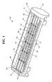
- One preferred embodiment of the present invention comprises the making of a razor head 10 and is illustrated in Figure 1 .
- Razor head 10 comprises a base 20, cap member 30, shaving aid 40, forward guard member 50, leading blade 60, middle blade 70 and cap blade 80.
- Each blade comprises a sharp edge 61, 71, 81, a first end 63, 73, 83 and a second end 65, 75, 85, respectively.
- a plurality of intermediate guard elements 90 extend over the leading edges 61, 71, 81 of each blade.
- the intermediate guard elements 90 of this illustrated embodiment are integrally formed with blade spacers 95, base 20 and cap member 30.
- guard element 90 spacers 95 and cap members 30 can be formed in a single injection molding step utilizing any suitable thermoplastic material such as polypropylene or ABS (acetalbutylstyrene).
- Guard elements 90 advantageously limit the amount of skin that can flow between adjacent blades and thereby minimizes the risk of nicks and cuts during shaving. While the embodiment of the razor head illustrated in Figure 1 comprises five intermediate guard elements 90, it is within the scope of the present invention to utilize either more or fewer guard elements as desired. As used herein with respect to the positioning of the guard elements, the terms “intermediate” and “intermediate portions” refer to the portions of the blades between first ends 63, 73, 83 and second ends 65, 75 and 85. The “intermediate” guard elements are spaced from the razor heads sidewalls 23 and 25 which commonly extend over the sides and forward corners of each blade in order to prevent those sharpened corners from nicking or cutting the person shaving.
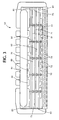
- forward guard member 50 is advantageously formed with a material comprising a higher coefficient of friction, e.g., rubber or rubber type compounds, than the thermoplastic utilized to form the base 20, guard elements 90 and cap member 30, in order to stretch the skin before it encounters the sharp edges of the blades.
- the forward guard element also comprises an irregular surface in order to provide better gripping of the skin surface prior to contact with the blades.
- forward guard member 50 advantageously comprises a plurality of recesses 52 and projections 54 in order to better grip the skin surface.
- Forward guard element 50 is preferably also formed in a molding process, most preferably during a sequential molding step following the molding of the blade support 20, cap 30, and guard elements 90.
- the shaving aid 40 can be formed of any desired materials, such as those known in the art, including but not limited to polyox, aloe vera, lanolin, vitamin E, etc. Shaving aid 40 is preferably molded within a recess of the cap 30 and is also preferably formed on razor head 10 in a sequential molding step before, after or simultaneously with the formation of forward guard member 50.
- each guard element 90 and spacer 95 advantageously support substantial portions of each blade in order to minimize the relative movement, e.g., deflection or "chatter", of the blades during shaving.
- these illustrated intermediate guard elements are formed with a wider base which tapers to a narrower skin engaging portion. The broader base provides greater blade support.
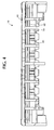
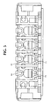
- the position of spacers 95 and guard elements 90 advantageously leave substantial open spaces which enhance rinsing of shaving debris, e.g., hair, shaving cream, etc., from the razor head.
- the bottom perspective view of Figure 4 also shows flexing members and wash through slots in the blades.
- the razor heads made according to the present invention can be rigid, flexible or can take forms other than the illustrated embodiments.
- the illustrated embodiment of Figures 1-5 is designed for attachment to a razor (not shown).
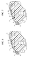
- Figure 6 is a cross sectional view of one embodiment of a razor head. This figure illustrates the distance D by which the leading skin engaging surface of guard element 90 precedes the sharp edges of each blade.
- the distance D is defined herein as the distance between the leading edge of a blade and the forward surface of the guard element as measured along a line perpendicular to the leading edge of the guard element. Since the guard elements of the various embodiments are formed utilizing molds, the distance D can be designed to be any distance desired.
- one advantage of the various embodiments of the razor head made according to the present invention when compared with wire wrapped blades is that the distance D can be greater or less than the width W of the guard elements, as illustrated in the front view of Figure 11 .
- a single guard element can have different distances D relative to one or more blades. As shown in Figure 6 , the distant D is less for seat blade 160 than the corresponding distance D of cap blade 180 along this single guard element 190.
- Figure 7 is a cross sectional view of an alternative embodiment of a razor head wherein the distances D for three blades are more constant those distances in the embodiment illustrated in Figure 6 . It is also within the scope of the present invention to manufacture a razor head comprising a plurality of intermediate guard elements wherein the distance D of a first guard element does not extend as far from the leading edges of a particular blade as does the leading edge of another guard element from the same blade.
- the present invention provides a very wide degree of design flexibility in changing the distance D and width W between different blades or at different intermediate positions along the same blade in order to optimize shave safety and comfort.
- the cross sectional views of Figures 6 and 7 also clearly illustrate how intermediate guard elements provide additional support to prevent unwanted movement of blade edges during shaving.
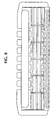
- Figure 8 is a top view of an alternative embodiment of a razor head. As compared to the guard elements shown in Figures 1-3 which have pyramidal cross sections for providing extra support to the blades, the guard elements 290 of Figure 8 have a constant width for their entire height.
- Figure 9 shows still another embodiment wherein the guard elements 390 are wider, having a width W .
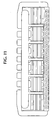
- one razor head made according to the present invention comprises guard elements 490 which are tapered in a manner which provides greater blade exposure for the seat blade and less exposure for the cap blade.
- the intermediate guard elements 590 also provide additional locations for skin engaging elements having different coefficients of friction than thermoplastic.
- shaving aid material 540 extends down from the cap area 530 along the length of the intermediate guard elements 590 in order to provide areas of low friction skin engaging contact.
- each of five intermediate skin engaging elements shows each of five intermediate skin engaging elements as supporting a "shaving aid" material
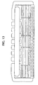
- Figure 12 illustrates a still further embodiment of a razor head wherein a high coefficient of friction material 650, for example, a rubber type compound, is positioned on the intermediate guard elements 690.
- a high coefficient of friction material 650 for example, a rubber type compound
- the high coefficient of friction material 650 can be positioned on all of the intermediate guard elements, on only some of the guard elements or on portions of one or more guard elements.
- one or more of the guard elements can support both a shaving aid and a high coefficient of friction material.
- guard elements 790 can be positioned at different locations along the length of the blade edges.
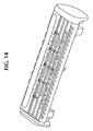
- At least one intermediate guard element 890 extends over a first blade edge 860 but not over a second blade edge 880. In this manner, the corresponding portion of the second blade edge 880 contacts the skin surface while a corresponding portion of another blade in the same razor head does not contact the skin surface. Therefore, in accordance with another aspect of the present invention, an example of which is shown in Figure 14 , an intermediate guard element may cover portions of one or more blades but not all of the blades in the razor head.
- One embodiment of a razor head made according to the present invention comprises a razor head comprising a blade support, at least one blade comprising a first end, a second end, intermediate portions and a sharp edge, and at least one and preferably a plurality of spaced intermediate molded skin engaging elements covering intermediate portions of the sharp edge. While the embodiment of the present invention illustrated in Figure 1 comprises three blades, at least some of the advantages of the present invention can be realized in a single blade or double blade razor head. Alternatively, more than three blades can be utilized.
- the materials utilized to form the molded guard elements of the present invention are most preferably thermoplastics such as polypropylene and ABS (acetalbutylstyrene) but can also comprise chemical resistant materials to maintain the integrity of the razor head.
- the guard elements can readily be molded and therefore the entire razor head can be molded in a single or sequential molding process.
- One preferred method of making a razor head according to the present invention comprises providing a plurality of blades each comprising a first end, a second end, intermediate portions and at least one sharp edge, arranging the plurality of blades in a mold cavity with the sharp edges in spaced relation, and molding a plurality of guard elements around spaced, intermediate portions of the leading edges of the blades. While the guard elements could conceivably be molded around unsharpened portions of the blade, with present technology it is preferable to provide blades with an entirely sharpened leading edge and for the intermediate guard elements to cover sharpened intermediate portions of the leading edge of the blade.
- one or more of the other elements of the razor head can be formed in a single step or in a separate, e.g. sequential, step.
- the base, cap and side walls can be formed before, during or after the molding of the guard elements.
- the base, side walls, cap, spacers and guard elements are formed in a single molding step. Then the shaving aid materials and high friction guard member are formed in one or more subsequent steps.
- a plurality of elements including some or each of the cap, blades, guard member, spacers, intermediate guard elements and end caps can be formed separately and then assembled.
- one or more intermediate guard elements can be integrally formed with spacers and the spacers are then assembled along with a base, cap and plurality of blades to form a razor head.
- a razor head made according to the present invention can be assembled comprising a cap member having downwardly extending intermediate guard elements which cover portions of one or more blade edges.
Landscapes
- Life Sciences & Earth Sciences (AREA)
- Forests & Forestry (AREA)
- Engineering & Computer Science (AREA)
- Mechanical Engineering (AREA)
- Dry Shavers And Clippers (AREA)
- Magnetic Heads (AREA)
Abstract
Description
- The present invention is directed to razor heads such as shaving cartridges and, more particularly, to razor heads comprising intermediate guard elements.
- Many razor heads found on the market have a guard member disposed forwardly of the cutting edges of two blades and a cap member. Each of these four elements contact the skin surface during shaving and, therefore, are often referred to as "skin-engaging" elements. In a typical safety razor, these four skin-engaging elements are disposed in a spaced relation such that a small space is provided between the guard member and the first blade edge, another space is provided between the two blade edges, and another space may be provided between the second blade edge and the skin-engaging portion of the cap member. Such spaces are typically provided between the skin-engaging portions of these four elements, though not necessarily between other portions of these elements which do not contact the skin. For example, the forward or "seat" blade may be attached directly to the guard member at a point remote from the cutting edge of the seat blade but a space would typically be provided between the skin-engaging surface of the guard member and the sharpened edge of the seat blade.
- Though it has been formerly recognized that the relative positioning and spacing of the skin-engaging portions of these skin-engaging elements affects the flow of skin across the cutting edges of the blades as well as the shaving angle at which the skin contacts the blade edges, it is desirable to provide still greater skin flow control.
- A relatively recent improvement to the field of wet shaving relating to the control of skin as it flows between blades is the use of wire wrapped blades. Wire wrapped blades comprise at least one metal wire wrapped, in spaced intervals, around the sharpened leading edge of a plurality of blades to limit the amount of skin that can flow between the blades. An example of a wet shaving razor with wire wrapped blades is disclosed in
US-A-5, 447,084 . - The use of wires to wrap blades provides an advantage during shaving, however, manufacturing is inherently complicated by the need to position the wires relative to the blade edges. Additionally, previously known wire wrapped blades have utilized a single size wire with a constant diameter which places limitations upon the shape and contour of the guard elements spaced along the cutting edge of the blades. Additionally, it can be difficult to secure wire guard elements across the cutting edge of a blade in a razor head. These wires also do not significantly inhibit movement of the blade edges in a direction perpendicular to a shaving stroke during shaving.
- From
US-A-5,318,429 it is known to use insert molding techniques for manufacturing a wet shaving razor unit. - Therefore, it would be desirable to provide a method for easily and relatively inexpensively manufacturing razor heads with improved skin flow controls, which provide greater design flexibility for controlling skin as it flows over the cutting edges of one or more blades during shaving, and which permit greater flexibility of the entire razor head during shaving.
- The present invention is directed to novel method of making a razor head as defined in claim 1 wherein the razor head comprises skin-engaging elements for razor heads including their design, construction and manufacture. The method of the present invention provides a razor head with a safe, close and comfortable shave while facilitating an easier, more reproducible and less expensive manufacturing process which provides greater design flexibility with respect to the size and positioning of guard elements, shaving aids and high coefficient of friction materials relative to the blades. Additionally, disclosed embodiments are also designed to facilitate the easy removal of shaving debris which accumulates in spaces of razor heads made according to the method of the present invention.
- In one embodiment of the present invention the method is used to manufacture a razor head comprising at least one blade having a first end, a second end, intermediate portions and a leading edge. A plurality of guard elements are molded over the leading edge at a plurality of intermediate portions. According to preferred embodiments of the present invention, the molded guard elements are integrally molded with one or more of a blade support, spacer element(s), forward guard member(s) or cap member(s). It is believed that the use of integrally molded guard elements, especially when the guard elements are integrally molded with blade supports or spacers, provide greater stability and allow less relative movement of the blade edges then wire wrapped blades since the molded guard elements tend to hold the blades in position more rigidly when the blades encounter hair during a shaving stroke. Those skilled in the art will appreciate that it is desirable to maintain predetermined blade spacing during shaving. Relative movements of the blade edges during shaving which significantly change the edge to edge spacing can result in a less than optimum shave. The various embodiments of the present invention also provide greater design flexibility in the size and shape of the intermediate guard elements. For example, the intermediate guard elements can readily extend outwardly from the blade edge any desired distance and a single razor head can readily be provided with guard elements which extend different distances from the edge of one blade or the edges of different blades.
- Additionally, in preferred embodiments, when the molded guard elements are aligned with spacers, these guard elements do not inhibit the rinsability of the razor head.
- The various embodiments of the present invention also advantageously provide additional sites for the placement of shaving aids and other skin flow control materials such as materials having high or low coefficients of friction.
- The present invention comprises methods of manufacturing a razor head by insert molding the razor head with a blade support, forward guard member, cap member, spacers and novel guard elements integrally molded in a single or sequential molding process.
- Other embodiments of the methods of the present invention comprise sequentially molding shaving aids and resilient skin engaging materials having high or low coefficients of friction onto skin engaging surfaces of the disclosed razor heads. The subject matter of the dependent claims relates to further individual embodiments of the present invention
-
-
Figure 1 is a perspective view of a razor head made according to one embodiment of the present invention. -
Figure 2 is an enlarged, partial perspective view of a portion of the razor head shown inFigure 1 . -
Figure 3 is a plan view of the razor head illustrated inFigure 1 . -
Figure 4 is a rear, perspective view of the razor head illustrated inFigure 1 . -
Figure 5 is a bottom perspective view of the razor head illustrated inFigure 1 . -
Figure 6 is a cross sectional view of another razor head made according to the method of the present invention. -
Figure 7 is a cross sectional view of an alternative embodiment of a razor head manufactured according to the present invention. -
Figure 8 is a top view of an embodiment of a razor head made according to the present invention comprising five, relatively thin intermediate guard elements. -
Figure 9 is a top view of an embodiment of razor head made according to the present invention and comprising five wider intermediate guard elements. -
Figure 10 is a top view of an embodiment of razor head made according to the present invention and comprising five tapered intermediate guard elements. -
Figure 11 is a top view of an embodiment of razor head made according to the present invention wherein a shaving aid extends from the cap forwardly on each of five intermediate guard elements. -
Figure 12 is a top view of an embodiment of razor head made according to the present invention and comprising high coefficient of friction material on each of five intermediate guard elements. -
Figure 13 is a top view of another embodiment of a razor head made according to the present invention wherein four intermediate guard elements are unevenly spaced. -
Figure 14 is a top view of a still further embodiment of razor head made according to the present invention wherein intermediate guard elements cover portions of some blades but not all blades. - The various embodiments of the present invention shown in the figures and described hereinbelow relate to the manufacturing of razor heads comprising molded, preferably thermoplastic, guard elements positioned over intermediate portions of at least one leading edge of a blade in order to provide enhanced skin flow control and blade stability during shaving. Accordingly, the various aspects of the present invention comprise novel methods of manufacturing razor heads as described in greater detail below. As used herein, the term "razor head" is meant to include cartridges adapted to be connected to a separate razor as well as the operative cutting portion of a disposable razor wherein the handle and cutting portion are formed as a single unit.
- One preferred embodiment of the present invention comprises the making of a
razor head 10 and is illustrated inFigure 1 . Razorhead 10 comprises a base 20,cap member 30, shavingaid 40,forward guard member 50, leadingblade 60,middle blade 70 andcap blade 80. Each blade comprises asharp edge first end second end intermediate guard elements 90 extend over the leadingedges Figure 2 theintermediate guard elements 90 of this illustrated embodiment are integrally formed withblade spacers 95, base 20 andcap member 30. From the present description, those skilled in the art will appreciate that these elements, namely the base 20,guard element 90,spacers 95 andcap members 30 can be formed in a single injection molding step utilizing any suitable thermoplastic material such as polypropylene or ABS (acetalbutylstyrene). -
Guard elements 90 advantageously limit the amount of skin that can flow between adjacent blades and thereby minimizes the risk of nicks and cuts during shaving. While the embodiment of the razor head illustrated inFigure 1 comprises fiveintermediate guard elements 90, it is within the scope of the present invention to utilize either more or fewer guard elements as desired. As used herein with respect to the positioning of the guard elements, the terms "intermediate" and "intermediate portions" refer to the portions of the blades betweenfirst ends second ends razor heads sidewalls 23 and 25 which commonly extend over the sides and forward corners of each blade in order to prevent those sharpened corners from nicking or cutting the person shaving. - In this illustrated embodiment,
forward guard member 50 is advantageously formed with a material comprising a higher coefficient of friction, e.g., rubber or rubber type compounds, than the thermoplastic utilized to form the base 20,guard elements 90 andcap member 30, in order to stretch the skin before it encounters the sharp edges of the blades. The forward guard element also comprises an irregular surface in order to provide better gripping of the skin surface prior to contact with the blades. In this illustrated embodiment,forward guard member 50 advantageously comprises a plurality ofrecesses 52 andprojections 54 in order to better grip the skin surface.Forward guard element 50 is preferably also formed in a molding process, most preferably during a sequential molding step following the molding of the blade support 20,cap 30, andguard elements 90. - The shaving
aid 40 can be formed of any desired materials, such as those known in the art, including but not limited to polyox, aloe vera, lanolin, vitamin E, etc. Shavingaid 40 is preferably molded within a recess of thecap 30 and is also preferably formed onrazor head 10 in a sequential molding step before, after or simultaneously with the formation offorward guard member 50. - According to this preferred illustrated embodiment, each
guard element 90 andspacer 95 advantageously support substantial portions of each blade in order to minimize the relative movement, e.g., deflection or "chatter", of the blades during shaving. As best shown inFigure 2 , these illustrated intermediate guard elements are formed with a wider base which tapers to a narrower skin engaging portion. The broader base provides greater blade support. As best shown inFigure 2 , the rear view ofFigure 4 , and bottom view ofFigure 5 , the position ofspacers 95 andguard elements 90 advantageously leave substantial open spaces which enhance rinsing of shaving debris, e.g., hair, shaving cream, etc., from the razor head. The bottom perspective view ofFigure 4 also shows flexing members and wash through slots in the blades. - The razor heads made according to the present invention can be rigid, flexible or can take forms other than the illustrated embodiments. The illustrated embodiment of
Figures 1-5 is designed for attachment to a razor (not shown). -
Figure 6 is a cross sectional view of one embodiment of a razor head. This figure illustrates the distance D by which the leading skin engaging surface ofguard element 90 precedes the sharp edges of each blade. The distance D is defined herein as the distance between the leading edge of a blade and the forward surface of the guard element as measured along a line perpendicular to the leading edge of the guard element. Since the guard elements of the various embodiments are formed utilizing molds, the distance D can be designed to be any distance desired. Moreover, one advantage of the various embodiments of the razor head made according to the present invention when compared with wire wrapped blades is that the distance D can be greater or less than the width W of the guard elements, as illustrated in the front view ofFigure 11 . It is also within the scope of the present invention to provide different size and different shape guard elements within a single razor head. Moreover a single guard element can have different distances D relative to one or more blades. As shown inFigure 6 , the distant D is less for seat blade 160 than the corresponding distance D of cap blade 180 along this single guard element 190. -
Figure 7 is a cross sectional view of an alternative embodiment of a razor head wherein the distances D for three blades are more constant those distances in the embodiment illustrated inFigure 6 . It is also within the scope of the present invention to manufacture a razor head comprising a plurality of intermediate guard elements wherein the distance D of a first guard element does not extend as far from the leading edges of a particular blade as does the leading edge of another guard element from the same blade. Thus, from the present description and drawings, it will be appreciated that the present invention provides a very wide degree of design flexibility in changing the distance D and width W between different blades or at different intermediate positions along the same blade in order to optimize shave safety and comfort. The cross sectional views ofFigures 6 and 7 also clearly illustrate how intermediate guard elements provide additional support to prevent unwanted movement of blade edges during shaving. -
Figure 8 is a top view of an alternative embodiment of a razor head. As compared to the guard elements shown inFigures 1-3 which have pyramidal cross sections for providing extra support to the blades, the guard elements 290 ofFigure 8 have a constant width for their entire height. -
Figure 9 shows still another embodiment wherein the guard elements 390 are wider, having a width W. - It is also within the scope of the present invention to manufacture a razor head comprising intermediate guard elements having different shapes. As illustrated in
Figure 10 , one razor head made according to the present invention comprises guard elements 490 which are tapered in a manner which provides greater blade exposure for the seat blade and less exposure for the cap blade. Other configurations are also possible. As illustrated in the embodiment ofFigure 11 , the intermediate guard elements 590 also provide additional locations for skin engaging elements having different coefficients of friction than thermoplastic. In the embodiment illustrated inFigure 11 , shaving aid material 540 extends down from the cap area 530 along the length of the intermediate guard elements 590 in order to provide areas of low friction skin engaging contact. While this illustrated embodiment shows each of five intermediate skin engaging elements as supporting a "shaving aid" material, it is also within the scope of the present invention to provide a shaving aid material on only one or more of the intermediate guard elements or only on portions of one or more of an intermediate element. -
Figure 12 illustrates a still further embodiment of a razor head wherein a high coefficient of friction material 650, for example, a rubber type compound, is positioned on the intermediate guard elements 690. As described above with respect to the shaving aid type material, the high coefficient of friction material 650 can be positioned on all of the intermediate guard elements, on only some of the guard elements or on portions of one or more guard elements. Though not illustrated, one or more of the guard elements can support both a shaving aid and a high coefficient of friction material. - Though the previously illustrated embodiments have shown guard elements which are substantially evenly spaced along the length of the blade edges, it is also within the scope of the present invention to provide one or more intermediate guard elements which are not evenly spaced. As shown in the embodiment illustrated in
Figure 13 , intermediate guard elements 790 can be positioned at different locations along the length of the blade edges. - According to a still further embodiment of a razor head, at least one intermediate guard element 890 extends over a first blade edge 860 but not over a second blade edge 880. In this manner, the corresponding portion of the second blade edge 880 contacts the skin surface while a corresponding portion of another blade in the same razor head does not contact the skin surface. Therefore, in accordance with another aspect of the present invention, an example of which is shown in
Figure 14 , an intermediate guard element may cover portions of one or more blades but not all of the blades in the razor head. - One embodiment of a razor head made according to the present invention comprises a razor head comprising a blade support, at least one blade comprising a first end, a second end, intermediate portions and a sharp edge, and at least one and preferably a plurality of spaced intermediate molded skin engaging elements covering intermediate portions of the sharp edge. While the embodiment of the present invention illustrated in
Figure 1 comprises three blades, at least some of the advantages of the present invention can be realized in a single blade or double blade razor head. Alternatively, more than three blades can be utilized. - The materials utilized to form the molded guard elements of the present invention are most preferably thermoplastics such as polypropylene and ABS (acetalbutylstyrene) but can also comprise chemical resistant materials to maintain the integrity of the razor head.
- As noted above, in the various embodiments of the present invention the guard elements can readily be molded and therefore the entire razor head can be molded in a single or sequential molding process. One preferred method of making a razor head according to the present invention comprises providing a plurality of blades each comprising a first end, a second end, intermediate portions and at least one sharp edge, arranging the plurality of blades in a mold cavity with the sharp edges in spaced relation, and molding a plurality of guard elements around spaced, intermediate portions of the leading edges of the blades. While the guard elements could conceivably be molded around unsharpened portions of the blade, with present technology it is preferable to provide blades with an entirely sharpened leading edge and for the intermediate guard elements to cover sharpened intermediate portions of the leading edge of the blade. Additionally, one or more of the other elements of the razor head can be formed in a single step or in a separate, e.g. sequential, step. For example, the base, cap and side walls can be formed before, during or after the molding of the guard elements. In the preferred illustrated embodiments, the base, side walls, cap, spacers and guard elements are formed in a single molding step. Then the shaving aid materials and high friction guard member are formed in one or more subsequent steps.
- According to a less preferred method of making razor heads of the present invention, a plurality of elements including some or each of the cap, blades, guard member, spacers, intermediate guard elements and end caps can be formed separately and then assembled. For example, one or more intermediate guard elements can be integrally formed with spacers and the spacers are then assembled along with a base, cap and plurality of blades to form a razor head. For example, a razor head made according to the present invention can be assembled comprising a cap member having downwardly extending intermediate guard elements which cover portions of one or more blade edges.
Claims (9)
- A method of making a razor head (10) comprising the steps of:providing a plurality of blades (60,70,80), each comprising a first end (63,73,83), a second end (65,75,85), a leading edge comprising intermediate portions and at least one sharp edge (61,71,81);arranging said plurality of blades (60, 70, 80) in a mold cavity with said sharp edges (61, 71, 81) in spaced relation;molding a plurality of guard elements (90) around spaced, intermediate portions of said sharp edges (61, 71, 81) of said blades (60, 70, 80).
- The method of making a razor head according to claim 1 wherein said molding step comprises molding a blade support (20).
- The method of making a razor head according to claim 2 wherein said guard elements (90) and said blade support (20) are integrally molded.
- The method of making a razor head according to claim 3 wherein said guard elements (90) and said blade support (20) are molded in a single step.
- The method of making a razor head according to claim 1 wherein said molding step comprises molding a cap member (30) and a shaving aid (40) in a sequential molding process.
- The method of making a razor head according to claim 1 further comprising the step of molding a shaving aid (40) onto said cap member (30).
- The method of making a razor head according to claim 1 comprising molding a flexible blade support (20).
- The method of making a razor head according to claim 1 comprising the step of molding a shaving aid (540) on at least one of said guard elements (590).
- The method of making a razor head according to claim 1 comprising the step of molding a material comprising a higher coefficient of friction than said blade support (20) on at least one of said intermediate guard elements (90).
Priority Applications (1)
| Application Number | Priority Date | Filing Date | Title |
|---|---|---|---|
| EP10168421.5A EP2233257B1 (en) | 2000-07-28 | 2001-07-24 | Razor heads with intermediate guard elements |
Applications Claiming Priority (3)
| Application Number | Priority Date | Filing Date | Title |
|---|---|---|---|
| US626194 | 2000-07-28 | ||
| US09/626,194 US6550141B1 (en) | 2000-07-28 | 2000-07-28 | Razor heads with intermediate guard elements |
| EP01306342A EP1184141B1 (en) | 2000-07-28 | 2001-07-24 | Razor heads with intermediate guard elements |
Related Parent Applications (2)
| Application Number | Title | Priority Date | Filing Date |
|---|---|---|---|
| EP01306342.5 Division | 2001-07-24 | ||
| EP01306342A Division EP1184141B1 (en) | 2000-07-28 | 2001-07-24 | Razor heads with intermediate guard elements |
Related Child Applications (1)
| Application Number | Title | Priority Date | Filing Date |
|---|---|---|---|
| EP10168421.5A Division EP2233257B1 (en) | 2000-07-28 | 2001-07-24 | Razor heads with intermediate guard elements |
Publications (3)
| Publication Number | Publication Date |
|---|---|
| EP1537964A2 EP1537964A2 (en) | 2005-06-08 |
| EP1537964A3 EP1537964A3 (en) | 2005-07-27 |
| EP1537964B1 true EP1537964B1 (en) | 2010-07-14 |
Family
ID=24509357
Family Applications (3)
| Application Number | Title | Priority Date | Filing Date |
|---|---|---|---|
| EP05004912A Expired - Lifetime EP1537964B1 (en) | 2000-07-28 | 2001-07-24 | Razor heads with intermediate guard elements |
| EP01306342A Expired - Lifetime EP1184141B1 (en) | 2000-07-28 | 2001-07-24 | Razor heads with intermediate guard elements |
| EP10168421.5A Expired - Lifetime EP2233257B1 (en) | 2000-07-28 | 2001-07-24 | Razor heads with intermediate guard elements |
Family Applications After (2)
| Application Number | Title | Priority Date | Filing Date |
|---|---|---|---|
| EP01306342A Expired - Lifetime EP1184141B1 (en) | 2000-07-28 | 2001-07-24 | Razor heads with intermediate guard elements |
| EP10168421.5A Expired - Lifetime EP2233257B1 (en) | 2000-07-28 | 2001-07-24 | Razor heads with intermediate guard elements |
Country Status (7)
| Country | Link |
|---|---|
| US (1) | US6550141B1 (en) |
| EP (3) | EP1537964B1 (en) |
| JP (2) | JP3850691B2 (en) |
| AT (2) | ATE308408T1 (en) |
| AU (1) | AU5597101A (en) |
| CA (1) | CA2354090A1 (en) |
| DE (2) | DE60114528T2 (en) |
Cited By (9)
| Publication number | Priority date | Publication date | Assignee | Title |
|---|---|---|---|---|
| US9718200B2 (en) | 2014-01-31 | 2017-08-01 | Dryfhout Enterprises, Llc | Safety razor with comb and integrated blade and associated methods |
| US9937629B1 (en) | 2016-05-17 | 2018-04-10 | Dryfhout Enterprises, Llc | Two-point discrimination safety razor assembly |
| US10131062B1 (en) | 2014-01-31 | 2018-11-20 | Dryfhout Enterprises, Llc | Body shaver with comb and blade |
| US10315322B1 (en) | 2016-05-17 | 2019-06-11 | Dryfhout Properties, Llc | Method of using a back shaver handle |
| US10493643B1 (en) | 2016-05-17 | 2019-12-03 | Dryfhout Properties, Llc | Leveled back shaver |
| US10500744B1 (en) | 2014-01-31 | 2019-12-10 | Dryfhout Properties, Llc | Safety razor with plurality of comb and integrated blade groups |
| US10543609B2 (en) | 2016-05-17 | 2020-01-28 | Dryfhout Properties, Llc | Elevated shaver |
| US11077570B2 (en) | 2014-01-31 | 2021-08-03 | Dryfhout Properties, Llc | Flexible back shaver |
| US12280512B2 (en) | 2014-01-31 | 2025-04-22 | Bakblade Limited | Safety razor with comb and blade |
Families Citing this family (45)
| Publication number | Priority date | Publication date | Assignee | Title |
|---|---|---|---|---|
| US20020095791A1 (en) * | 2001-01-23 | 2002-07-25 | Pennella Andrew J. | Razor blade cartridge having guard ribs and methods therefor |
| EP1472055B1 (en) * | 2002-01-30 | 2005-11-23 | Eveready Battery Company, Inc. | Guard bar for a razor cartridge |
| US20050015991A1 (en) * | 2002-04-24 | 2005-01-27 | Eveready Battery Company, Inc. | Razor cartridge |
| US7210229B2 (en) * | 2002-04-24 | 2007-05-01 | Eveready Battery Company, Inc. | Razor cartridge |
| US6852262B2 (en) * | 2002-05-09 | 2005-02-08 | The Gillette Company | Insert molding razor cartridges |
| TWI333545B (en) * | 2003-04-02 | 2010-11-21 | Cholestech Corp | Adhered membranes retaining porosity and biological activity |
| USD516243S1 (en) * | 2003-12-02 | 2006-02-28 | Kai R & D Center Co., Ltd. | Replaceable razor cartridge |
| GB2413980A (en) * | 2004-05-12 | 2005-11-16 | Ian Stephen Bell | Razor head |
| DE602005026979D1 (en) * | 2004-10-05 | 2011-04-28 | Eveready Battery Inc | SHAVER |
| US20060272154A1 (en) * | 2005-06-02 | 2006-12-07 | Brevard Alfred S | Disposable gel-dispensing razor |
| US7681314B2 (en) * | 2005-06-10 | 2010-03-23 | Eveready Battery Company Inc. | Inter-blade guard and method for manufacturing same |
| USD560034S1 (en) * | 2007-03-12 | 2008-01-15 | Eveready Battery Company, Inc. | Razor cartridge |
| US8438736B2 (en) * | 2007-08-24 | 2013-05-14 | The Gillette Company | Safety razor with improved guard |
| US9221185B2 (en) * | 2008-09-10 | 2015-12-29 | The Gillette Company | Shaving razors and cartridges |
| US8209867B2 (en) * | 2008-10-02 | 2012-07-03 | The Gillette Company | Shaving razors and cartridges |
| US8782903B2 (en) * | 2009-05-29 | 2014-07-22 | The Gillette Company | Shaving razor comb guard for a trimming blade |
| US8273205B2 (en) | 2009-07-24 | 2012-09-25 | The Gillette Company | Manufacture of pivoting resilient skin contacting members |
| US20110119923A1 (en) | 2009-11-20 | 2011-05-26 | Roy Nicoll | Razors and kits for applying shaving aids |
| EP2512761B2 (en) * | 2009-12-18 | 2025-06-04 | The Gillette Company LLC | Razor cartridge with non-cutting element |
| US8726518B2 (en) * | 2010-03-16 | 2014-05-20 | The Gillette Company | Shaving razors and cartridges |
| USD633253S1 (en) | 2010-06-23 | 2011-02-22 | American Safety Razor | Razor cartridge |
| USD648075S1 (en) | 2010-07-07 | 2011-11-01 | American Safety Razor | Razor cartridge |
| USD640415S1 (en) | 2010-07-07 | 2011-06-21 | American Safety Razor | Razor cartridge |
| USD643976S1 (en) | 2010-10-19 | 2011-08-23 | American Safety Razor | Razor cartridge |
| USD643977S1 (en) | 2010-10-19 | 2011-08-23 | American Safety Razor | Razor cartridge |
| US9492933B2 (en) | 2011-09-30 | 2016-11-15 | The Gillette Company | Guard for a shaving razor |
| US8931379B2 (en) * | 2012-10-17 | 2015-01-13 | David L. Allyn | Methods and devices for safely handling a razor blade |
| US9457486B2 (en) * | 2013-03-13 | 2016-10-04 | Rolling Razor, Inc | Shaving cartridge with individual blade guards |
| BR112016010021B1 (en) * | 2013-11-08 | 2021-09-21 | Bic-Violex Sa | SHAVING BLADE HEAD AND WET SHAVING BLADE |
| US20160082610A1 (en) * | 2014-09-24 | 2016-03-24 | Lfnb, Llc | Razor assembly |
| FR3047193A1 (en) * | 2016-02-02 | 2017-08-04 | Vincent Pierre Auguste Neppel | MANUAL MECHANICAL RAZOR AT HEIGHT |
| MX2018011289A (en) | 2016-03-18 | 2019-02-18 | Personal Care Marketing And Res Inc | Razor cartridge. |
| EP3231565B1 (en) * | 2016-03-31 | 2019-09-18 | The Gillette Company LLC | Razor cartridge with fluid management |
| USD877983S1 (en) | 2016-09-09 | 2020-03-10 | The Gillette Company Llc | Shaving razor cartridge |
| EP3292965B1 (en) | 2016-09-09 | 2021-05-26 | The Gillette Company LLC | Shaving razor cartridge and method of assembling |
| US9993931B1 (en) | 2016-11-23 | 2018-06-12 | Personal Care Marketing And Research, Inc. | Razor docking and pivot |
| US11117278B2 (en) | 2017-06-06 | 2021-09-14 | The Gillette Company Llc | Shaving razor cartridge |
| USD884971S1 (en) | 2019-02-27 | 2020-05-19 | Pcmr International Ltd | Razor cartridge |
| USD884970S1 (en) | 2019-02-27 | 2020-05-19 | PCMR International Ltd. | Razor cartridge guard |
| USD884969S1 (en) | 2019-02-27 | 2020-05-19 | Pcmr International Ltd | Combined razor cartridge guard and docking |
| USD921984S1 (en) | 2019-03-19 | 2021-06-08 | The Gillette Company Llc | Shaving razor cartridge |
| EP3868526A1 (en) * | 2020-02-24 | 2021-08-25 | Société BIC | Razor cartridge |
| USD965887S1 (en) | 2020-05-20 | 2022-10-04 | The Gillette Company Llc | Shaving razor guard bar |
| US11000960B1 (en) | 2020-11-16 | 2021-05-11 | Personal Care Marketing And Research, Inc. | Razor exposure |
| US20240116203A1 (en) * | 2022-10-11 | 2024-04-11 | Planet Earth Razors Ab | Razor cartridge |
Family Cites Families (21)
| Publication number | Priority date | Publication date | Assignee | Title |
|---|---|---|---|---|
| CA1102537A (en) | 1977-09-08 | 1981-06-09 | Frank A. Ferraro | Shaving cartridge |
| GB2178687A (en) | 1985-08-09 | 1987-02-18 | Joseph George Feinberg | Razor blade |
| US5318429A (en) | 1987-04-24 | 1994-06-07 | Warner-Lambert Company | Process for insert molding wet-shaving razor unit and unit made therefrom |
| US4854043A (en) | 1987-10-30 | 1989-08-08 | Warner-Lambert Company | Flexible razor head |
| DE3743298A1 (en) * | 1987-12-19 | 1989-06-29 | Wilkinson Sword Gmbh | SHAVING APPARATUS AND METHOD FOR PRODUCING A LAYER OF LOW FRICTION RESISTANCE ON A SHAVING APPARATUS |
| GB8806813D0 (en) * | 1988-03-22 | 1988-04-20 | Fenn D J | Shaving device |
| US5313705A (en) | 1991-05-13 | 1994-05-24 | Warner-Lambert Company | Segmented guard bar with improved skin flow control |
| GB2288760B (en) | 1992-03-06 | 1996-01-03 | Wilkinson Sword Gmbh | Razor head of a wet razor |
| GB2265565B (en) | 1992-03-28 | 1995-03-22 | Wilkinson Sword Gmbh | Razor head of a wet razor |
| ZA951655B (en) * | 1994-04-28 | 1995-12-08 | Warner Lambert Co | Dynamic flexible razor head |
| JPH07303767A (en) * | 1994-05-13 | 1995-11-21 | Feather Safety Razor Co Ltd | Spare blade cartridge |
| US5903979A (en) * | 1994-07-13 | 1999-05-18 | The Gillette Company | Safety razors |
| WO1996004111A1 (en) | 1994-07-29 | 1996-02-15 | Warner-Lambert Company | Razor head with enhanced skin protection |
| US5456009A (en) * | 1994-08-23 | 1995-10-10 | Warner-Lambert Company | Multi-blade razor head with improved performance |
| JPH0938357A (en) * | 1995-05-22 | 1997-02-10 | Kaijirushi Hamono Kaihatsu Center:Kk | Replacement blade for razor |
| JPH09135972A (en) | 1995-11-17 | 1997-05-27 | Kaijirushi Hamono Kaihatsu Center:Kk | Safety razor |
| JP2757157B2 (en) | 1995-11-17 | 1998-05-25 | 株式会社貝印刃物開発センター | Safety razor |
| US5794343A (en) | 1997-05-12 | 1998-08-18 | The Gillette Company | Razor blade assembly |
| JP2952587B1 (en) * | 1998-03-30 | 1999-09-27 | 株式会社貝印刃物開発センター | Safety razor |
| US6131287A (en) * | 1998-06-08 | 2000-10-17 | American Safety Razor Company | Razor cartridge with dimpled blade guard |
| JP2000167269A (en) * | 2000-02-07 | 2000-06-20 | Mandom Corp | Body hair shaving tool |
-
2000
- 2000-07-28 US US09/626,194 patent/US6550141B1/en not_active Expired - Lifetime
-
2001
- 2001-07-24 CA CA002354090A patent/CA2354090A1/en not_active Abandoned
- 2001-07-24 DE DE60114528T patent/DE60114528T2/en not_active Expired - Lifetime
- 2001-07-24 DE DE60142589T patent/DE60142589D1/en not_active Expired - Lifetime
- 2001-07-24 EP EP05004912A patent/EP1537964B1/en not_active Expired - Lifetime
- 2001-07-24 EP EP01306342A patent/EP1184141B1/en not_active Expired - Lifetime
- 2001-07-24 AT AT01306342T patent/ATE308408T1/en not_active IP Right Cessation
- 2001-07-24 AT AT05004912T patent/ATE473845T1/en not_active IP Right Cessation
- 2001-07-24 EP EP10168421.5A patent/EP2233257B1/en not_active Expired - Lifetime
- 2001-07-25 AU AU55971/01A patent/AU5597101A/en not_active Abandoned
- 2001-07-27 JP JP2001228284A patent/JP3850691B2/en not_active Expired - Fee Related
-
2006
- 2006-04-26 JP JP2006121936A patent/JP4282685B2/en not_active Expired - Fee Related
Cited By (10)
| Publication number | Priority date | Publication date | Assignee | Title |
|---|---|---|---|---|
| US9718200B2 (en) | 2014-01-31 | 2017-08-01 | Dryfhout Enterprises, Llc | Safety razor with comb and integrated blade and associated methods |
| US10131062B1 (en) | 2014-01-31 | 2018-11-20 | Dryfhout Enterprises, Llc | Body shaver with comb and blade |
| US10500744B1 (en) | 2014-01-31 | 2019-12-10 | Dryfhout Properties, Llc | Safety razor with plurality of comb and integrated blade groups |
| US11077570B2 (en) | 2014-01-31 | 2021-08-03 | Dryfhout Properties, Llc | Flexible back shaver |
| US11104018B2 (en) | 2014-01-31 | 2021-08-31 | Dryfhout Properties, Llc | Safety razor with comb and blade |
| US12280512B2 (en) | 2014-01-31 | 2025-04-22 | Bakblade Limited | Safety razor with comb and blade |
| US9937629B1 (en) | 2016-05-17 | 2018-04-10 | Dryfhout Enterprises, Llc | Two-point discrimination safety razor assembly |
| US10315322B1 (en) | 2016-05-17 | 2019-06-11 | Dryfhout Properties, Llc | Method of using a back shaver handle |
| US10493643B1 (en) | 2016-05-17 | 2019-12-03 | Dryfhout Properties, Llc | Leveled back shaver |
| US10543609B2 (en) | 2016-05-17 | 2020-01-28 | Dryfhout Properties, Llc | Elevated shaver |
Also Published As
| Publication number | Publication date |
|---|---|
| CA2354090A1 (en) | 2002-01-28 |
| EP1184141A2 (en) | 2002-03-06 |
| EP2233257A1 (en) | 2010-09-29 |
| DE60114528T2 (en) | 2006-06-01 |
| JP2002052272A (en) | 2002-02-19 |
| DE60142589D1 (en) | 2010-08-26 |
| EP1184141B1 (en) | 2005-11-02 |
| ATE473845T1 (en) | 2010-07-15 |
| EP1537964A3 (en) | 2005-07-27 |
| DE60114528D1 (en) | 2005-12-08 |
| EP1184141A3 (en) | 2002-03-13 |
| EP1537964A2 (en) | 2005-06-08 |
| ATE308408T1 (en) | 2005-11-15 |
| JP3850691B2 (en) | 2006-11-29 |
| US6550141B1 (en) | 2003-04-22 |
| EP2233257B1 (en) | 2014-12-24 |
| JP2006198433A (en) | 2006-08-03 |
| AU5597101A (en) | 2002-01-31 |
| JP4282685B2 (en) | 2009-06-24 |
Similar Documents
| Publication | Publication Date | Title |
|---|---|---|
| EP1537964B1 (en) | Razor heads with intermediate guard elements | |
| US9296117B2 (en) | Shaving cartridges having a plurality of arrays | |
| EP2272639B1 (en) | Razor cartridge with inter-blade guard | |
| EP0336355B1 (en) | Multiple blade safety razor | |
| EP1097788B1 (en) | Razor assembly | |
| EP2178681B1 (en) | Safety razor with improved guard | |
| EP1937444B1 (en) | Blade mounting members for a razor cartridge | |
| EP0858868A1 (en) | Razor head with moveable blade package | |
| CN115003469B (en) | Cutter system, electric shaver or trimmer and method of manufacturing a cutter system | |
| KR20070015143A (en) | Shaver | |
| US20080313910A1 (en) | Cutter blade assembly and dry shaver for variable height of cut | |
| EP0667812B1 (en) | Rotary powered dynamic shaving system with shaving aid | |
| GB2265328A (en) | Razor head of a wet razor | |
| US20040103538A1 (en) | Razor cartridge | |
| EP1910043B1 (en) | Electric razor foil | |
| EP1960163A1 (en) | Cutter blade assembly and dry shaver for variable height of cut | |
| HK1113107A1 (en) | Dry shaver | |
| MXPA99010328A (en) | Razor assembly |
Legal Events
| Date | Code | Title | Description |
|---|---|---|---|
| PUAI | Public reference made under article 153(3) epc to a published international application that has entered the european phase |
Free format text: ORIGINAL CODE: 0009012 |
|
| 17P | Request for examination filed |
Effective date: 20050307 |
|
| AC | Divisional application: reference to earlier application |
Ref document number: 1184141 Country of ref document: EP Kind code of ref document: P |
|
| AK | Designated contracting states |
Kind code of ref document: A2 Designated state(s): AT BE CH CY DE DK ES FI FR GB GR IE IT LI LU MC NL PT SE TR |
|
| PUAL | Search report despatched |
Free format text: ORIGINAL CODE: 0009013 |
|
| AK | Designated contracting states |
Kind code of ref document: A3 Designated state(s): AT BE CH CY DE DK ES FI FR GB GR IE IT LI LU MC NL PT SE TR |
|
| AKX | Designation fees paid |
Designated state(s): AT BE CH CY DE DK ES FI FR GB GR IE IT LI LU MC NL PT SE TR |
|
| 17Q | First examination report despatched |
Effective date: 20070822 |
|
| GRAP | Despatch of communication of intention to grant a patent |
Free format text: ORIGINAL CODE: EPIDOSNIGR1 |
|
| GRAS | Grant fee paid |
Free format text: ORIGINAL CODE: EPIDOSNIGR3 |
|
| GRAA | (expected) grant |
Free format text: ORIGINAL CODE: 0009210 |
|
| AC | Divisional application: reference to earlier application |
Ref document number: 1184141 Country of ref document: EP Kind code of ref document: P |
|
| AK | Designated contracting states |
Kind code of ref document: B1 Designated state(s): AT BE CH CY DE DK ES FI FR GB GR IE IT LI LU MC NL PT SE TR |
|
| REG | Reference to a national code |
Ref country code: GB Ref legal event code: FG4D |
|
| REG | Reference to a national code |
Ref country code: CH Ref legal event code: EP |
|
| REG | Reference to a national code |
Ref country code: IE Ref legal event code: FG4D |
|
| REF | Corresponds to: |
Ref document number: 60142589 Country of ref document: DE Date of ref document: 20100826 Kind code of ref document: P |
|
| REG | Reference to a national code |
Ref country code: NL Ref legal event code: VDEP Effective date: 20100714 |
|
| PG25 | Lapsed in a contracting state [announced via postgrant information from national office to epo] |
Ref country code: FI Free format text: LAPSE BECAUSE OF FAILURE TO SUBMIT A TRANSLATION OF THE DESCRIPTION OR TO PAY THE FEE WITHIN THE PRESCRIBED TIME-LIMIT Effective date: 20100714 Ref country code: AT Free format text: LAPSE BECAUSE OF FAILURE TO SUBMIT A TRANSLATION OF THE DESCRIPTION OR TO PAY THE FEE WITHIN THE PRESCRIBED TIME-LIMIT Effective date: 20100714 Ref country code: NL Free format text: LAPSE BECAUSE OF FAILURE TO SUBMIT A TRANSLATION OF THE DESCRIPTION OR TO PAY THE FEE WITHIN THE PRESCRIBED TIME-LIMIT Effective date: 20100714 |
|
| PG25 | Lapsed in a contracting state [announced via postgrant information from national office to epo] |
Ref country code: PT Free format text: LAPSE BECAUSE OF FAILURE TO SUBMIT A TRANSLATION OF THE DESCRIPTION OR TO PAY THE FEE WITHIN THE PRESCRIBED TIME-LIMIT Effective date: 20101115 Ref country code: MC Free format text: LAPSE BECAUSE OF NON-PAYMENT OF DUE FEES Effective date: 20100731 Ref country code: CY Free format text: LAPSE BECAUSE OF FAILURE TO SUBMIT A TRANSLATION OF THE DESCRIPTION OR TO PAY THE FEE WITHIN THE PRESCRIBED TIME-LIMIT Effective date: 20100714 |
|
| REG | Reference to a national code |
Ref country code: CH Ref legal event code: PL |
|
| PG25 | Lapsed in a contracting state [announced via postgrant information from national office to epo] |
Ref country code: SE Free format text: LAPSE BECAUSE OF FAILURE TO SUBMIT A TRANSLATION OF THE DESCRIPTION OR TO PAY THE FEE WITHIN THE PRESCRIBED TIME-LIMIT Effective date: 20100714 Ref country code: GR Free format text: LAPSE BECAUSE OF FAILURE TO SUBMIT A TRANSLATION OF THE DESCRIPTION OR TO PAY THE FEE WITHIN THE PRESCRIBED TIME-LIMIT Effective date: 20101015 Ref country code: BE Free format text: LAPSE BECAUSE OF FAILURE TO SUBMIT A TRANSLATION OF THE DESCRIPTION OR TO PAY THE FEE WITHIN THE PRESCRIBED TIME-LIMIT Effective date: 20100714 |
|
| PG25 | Lapsed in a contracting state [announced via postgrant information from national office to epo] |
Ref country code: LI Free format text: LAPSE BECAUSE OF NON-PAYMENT OF DUE FEES Effective date: 20100731 Ref country code: CH Free format text: LAPSE BECAUSE OF NON-PAYMENT OF DUE FEES Effective date: 20100731 Ref country code: DK Free format text: LAPSE BECAUSE OF FAILURE TO SUBMIT A TRANSLATION OF THE DESCRIPTION OR TO PAY THE FEE WITHIN THE PRESCRIBED TIME-LIMIT Effective date: 20100714 |
|
| PLBE | No opposition filed within time limit |
Free format text: ORIGINAL CODE: 0009261 |
|
| STAA | Information on the status of an ep patent application or granted ep patent |
Free format text: STATUS: NO OPPOSITION FILED WITHIN TIME LIMIT |
|
| PG25 | Lapsed in a contracting state [announced via postgrant information from national office to epo] |
Ref country code: IT Free format text: LAPSE BECAUSE OF FAILURE TO SUBMIT A TRANSLATION OF THE DESCRIPTION OR TO PAY THE FEE WITHIN THE PRESCRIBED TIME-LIMIT Effective date: 20100714 |
|
| 26N | No opposition filed |
Effective date: 20110415 |
|
| PG25 | Lapsed in a contracting state [announced via postgrant information from national office to epo] |
Ref country code: ES Free format text: LAPSE BECAUSE OF FAILURE TO SUBMIT A TRANSLATION OF THE DESCRIPTION OR TO PAY THE FEE WITHIN THE PRESCRIBED TIME-LIMIT Effective date: 20101025 |
|
| REG | Reference to a national code |
Ref country code: DE Ref legal event code: R097 Ref document number: 60142589 Country of ref document: DE Effective date: 20110415 |
|
| PG25 | Lapsed in a contracting state [announced via postgrant information from national office to epo] |
Ref country code: IE Free format text: LAPSE BECAUSE OF NON-PAYMENT OF DUE FEES Effective date: 20100724 |
|
| PG25 | Lapsed in a contracting state [announced via postgrant information from national office to epo] |
Ref country code: LU Free format text: LAPSE BECAUSE OF NON-PAYMENT OF DUE FEES Effective date: 20100724 |
|
| PG25 | Lapsed in a contracting state [announced via postgrant information from national office to epo] |
Ref country code: TR Free format text: LAPSE BECAUSE OF FAILURE TO SUBMIT A TRANSLATION OF THE DESCRIPTION OR TO PAY THE FEE WITHIN THE PRESCRIBED TIME-LIMIT Effective date: 20100714 |
|
| REG | Reference to a national code |
Ref country code: FR Ref legal event code: PLFP Year of fee payment: 16 |
|
| PGFP | Annual fee paid to national office [announced via postgrant information from national office to epo] |
Ref country code: DE Payment date: 20160726 Year of fee payment: 16 Ref country code: GB Payment date: 20160727 Year of fee payment: 16 |
|
| PGFP | Annual fee paid to national office [announced via postgrant information from national office to epo] |
Ref country code: FR Payment date: 20160726 Year of fee payment: 16 |
|
| REG | Reference to a national code |
Ref country code: DE Ref legal event code: R119 Ref document number: 60142589 Country of ref document: DE |
|
| GBPC | Gb: european patent ceased through non-payment of renewal fee |
Effective date: 20170724 |
|
| REG | Reference to a national code |
Ref country code: FR Ref legal event code: ST Effective date: 20180330 |
|
| PG25 | Lapsed in a contracting state [announced via postgrant information from national office to epo] |
Ref country code: DE Free format text: LAPSE BECAUSE OF NON-PAYMENT OF DUE FEES Effective date: 20180201 Ref country code: GB Free format text: LAPSE BECAUSE OF NON-PAYMENT OF DUE FEES Effective date: 20170724 |
|
| PG25 | Lapsed in a contracting state [announced via postgrant information from national office to epo] |
Ref country code: FR Free format text: LAPSE BECAUSE OF NON-PAYMENT OF DUE FEES Effective date: 20170731 |