EP1589408A2 - Dispositif d'affichage avec une fonction d'entrée optique - Google Patents
Dispositif d'affichage avec une fonction d'entrée optique Download PDFInfo
- Publication number
- EP1589408A2 EP1589408A2 EP05008618A EP05008618A EP1589408A2 EP 1589408 A2 EP1589408 A2 EP 1589408A2 EP 05008618 A EP05008618 A EP 05008618A EP 05008618 A EP05008618 A EP 05008618A EP 1589408 A2 EP1589408 A2 EP 1589408A2
- Authority
- EP
- European Patent Office
- Prior art keywords
- light
- light source
- display screen
- unit
- source device
- Prior art date
- Legal status (The legal status is an assumption and is not a legal conclusion. Google has not performed a legal analysis and makes no representation as to the accuracy of the status listed.)
- Withdrawn
Links
Images


Classifications
-
- G—PHYSICS
- G06—COMPUTING OR CALCULATING; COUNTING
- G06F—ELECTRIC DIGITAL DATA PROCESSING
- G06F3/00—Input arrangements for transferring data to be processed into a form capable of being handled by the computer; Output arrangements for transferring data from processing unit to output unit, e.g. interface arrangements
- G06F3/01—Input arrangements or combined input and output arrangements for interaction between user and computer
- G06F3/03—Arrangements for converting the position or the displacement of a member into a coded form
- G06F3/033—Pointing devices displaced or positioned by the user, e.g. mice, trackballs, pens or joysticks; Accessories therefor
- G06F3/0354—Pointing devices displaced or positioned by the user, e.g. mice, trackballs, pens or joysticks; Accessories therefor with detection of two-dimensional [2D] relative movements between the device, or an operating part thereof, and a plane or surface, e.g. 2D mice, trackballs, pens or pucks
-
- G—PHYSICS
- G06—COMPUTING OR CALCULATING; COUNTING
- G06F—ELECTRIC DIGITAL DATA PROCESSING
- G06F3/00—Input arrangements for transferring data to be processed into a form capable of being handled by the computer; Output arrangements for transferring data from processing unit to output unit, e.g. interface arrangements
- G06F3/01—Input arrangements or combined input and output arrangements for interaction between user and computer
- G06F3/03—Arrangements for converting the position or the displacement of a member into a coded form
- G06F3/033—Pointing devices displaced or positioned by the user, e.g. mice, trackballs, pens or joysticks; Accessories therefor
- G06F3/038—Control and interface arrangements therefor, e.g. drivers or device-embedded control circuitry
- G06F3/0386—Control and interface arrangements therefor, e.g. drivers or device-embedded control circuitry for light pen
-
- G—PHYSICS
- G06—COMPUTING OR CALCULATING; COUNTING
- G06F—ELECTRIC DIGITAL DATA PROCESSING
- G06F3/00—Input arrangements for transferring data to be processed into a form capable of being handled by the computer; Output arrangements for transferring data from processing unit to output unit, e.g. interface arrangements
- G06F3/01—Input arrangements or combined input and output arrangements for interaction between user and computer
- G06F3/03—Arrangements for converting the position or the displacement of a member into a coded form
- G06F3/033—Pointing devices displaced or positioned by the user, e.g. mice, trackballs, pens or joysticks; Accessories therefor
- G06F3/0354—Pointing devices displaced or positioned by the user, e.g. mice, trackballs, pens or joysticks; Accessories therefor with detection of two-dimensional [2D] relative movements between the device, or an operating part thereof, and a plane or surface, e.g. 2D mice, trackballs, pens or pucks
- G06F3/03545—Pens or stylus
-
- G—PHYSICS
- G06—COMPUTING OR CALCULATING; COUNTING
- G06F—ELECTRIC DIGITAL DATA PROCESSING
- G06F3/00—Input arrangements for transferring data to be processed into a form capable of being handled by the computer; Output arrangements for transferring data from processing unit to output unit, e.g. interface arrangements
- G06F3/01—Input arrangements or combined input and output arrangements for interaction between user and computer
- G06F3/03—Arrangements for converting the position or the displacement of a member into a coded form
- G06F3/041—Digitisers, e.g. for touch screens or touch pads, characterised by the transducing means
- G06F3/0412—Digitisers structurally integrated in a display
-
- G—PHYSICS
- G06—COMPUTING OR CALCULATING; COUNTING
- G06F—ELECTRIC DIGITAL DATA PROCESSING
- G06F3/00—Input arrangements for transferring data to be processed into a form capable of being handled by the computer; Output arrangements for transferring data from processing unit to output unit, e.g. interface arrangements
- G06F3/01—Input arrangements or combined input and output arrangements for interaction between user and computer
- G06F3/03—Arrangements for converting the position or the displacement of a member into a coded form
- G06F3/041—Digitisers, e.g. for touch screens or touch pads, characterised by the transducing means
- G06F3/042—Digitisers, e.g. for touch screens or touch pads, characterised by the transducing means by opto-electronic means
Definitions
- the present invention relates to a display device capable of inputting positional information by use of light from a light source irradiated onto a display screen.
- a liquid crystal display device includes an array substrate in which pixels are arranged at respective intersections of a plurality of scan lines and a plurality of signal lines, and drive circuits for driving the scan lines and the signal lines.
- Each of the pixels includes a thin film transistor (TFT), a liquid crystal capacitor, and an auxiliary capacitor.
- TFT thin film transistor
- auxiliary capacitor an auxiliary capacitor
- a display device including an optical sensor element on an array substrate and having an optical input function for capturing an image by using the light.
- respective pixels include photodiodes as the optical sensor elements, for example.
- a capacitor is connected to each of the photodiodes. Since a charge quantity of the capacitor varies depending on an amount of light received by the photodiode, it is possible to generate image data by detecting voltages on both ends of the capacitor.
- This display device offers image processing capable of producing multiple tone image data corresponding to irradiation strength of incident light.
- a method of importing data while displaying the image by inserting an image capturing frame between display frames for displaying an image By using this method, it is possible to use a display device as a coordinate input device by touching a display screen with a finger or by irradiating light onto the display screen with a pen-shaped light source.
- the optical sensor element also reacts to outside environment light other than the light from the light source. Accordingly, depending on the environment, malfunction may occur during the coordinate input processing.
- An object of the present invention is to detect pressure of a light source against a display screen.
- Another object of the present invention is to prevent malfunction caused by the outside environment light.
- Still another object of the present invention is to reduce power consumption of a light source.
- An optical input display device of the present invention includes a light source device and a display device.
- the light source device includes: a light source unit configured to irradiate light when a tip of the light source unit is pressed against a display screen of the display device; and a light transmission unit configured to transmit the light from the light source unit so as to change any of light reception intensity and a light receiving region on the display screen in response to a degree of pressure.
- the display device includes: a display unit including pixel units configured to display image signals supplied through signal lines and photodetector units configured to detect the light irradiated from the light source device onto the display screen, the pixel units and the photodetector units being provided on intersections of a plurality of scan lines and the plurality of signal lines; a light reception and detection unit configured to detect any of light reception intensity and the light receiving region of the light from the light transmission unit on the display screen based on light detection signals from the photodetector units; and a distance calculation unit configured to calculate a distance between the light transmission unit and the display screen based on any of the detected light reception intensity and the detected light receiving region.
- the light source device when the tip of the light source device is pressed against the display screen, the light source device changes the area of the light receiving region in response to the degree of this pressure. Meanwhile, the distance calculation unit of the display device calculates the distance between the light transmission unit of the light source device and the display screen based on this light receiving region. In another case, the light source device changes the light reception intensity on the display screen in response to the degree of the pressure against the display screen. Meanwhile, the distance calculation unit calculates the distance between the light transmission unit and the display screen based on this light reception intensity. By using this distance, it is possible to detect the degree of pressure of the light source device against the display screen.
- the light source unit does not output the light when the tip of the light source unit is not pressed against the display screen. Therefore, it is possible to prevent malfunction attributable to outside environment light and to reduce power consumption by the light source unit by stopping the light detecting operation in the display unit.
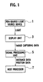
- an optical input display device includes a pen-shaped light source device 1 and a display device.
- This display device includes a display unit 3, a signal processing unit 5, and a host processor 7.
- the light source device 1 includes a light source unit configured to irradiate light when a pen tip at an end of the light source device 1 is pressed against a display screen of the display device, and a light transmission unit configured to transmit the light from the light source unit so as to change an area of a light receiving region on the display screen in response to a degree of pressure of the pen tip.
- the display unit 3 has a display function for displaying an arbitrary image on the display screen, and an optical input function for detecting the light irradiated from the light source device 1 onto the display screen.
- the signal processing unit 5 includes a light reception and detection unit, a distance calculation unit, and a position calculation unit.
- the light reception and detection unit receives a light detection signal detected by the display unit 3 and detects the light receiving region on the display screen based on this light detection signal.
- the distance calculation unit calculates a distance between the light transmission unit of the light source device 1 and the display screen based on the detected light receiving region.
- the position calculation unit calculates a position of irradiation of the light on the display screen based on the detected light receiving region.
- the host processor 7 receives distance data and position data from the signal processing unit 5 and performs a variety of processing. For example, the host processor 7 connects a plurality of positions of the display screen specified by a plurality of pieces of the position data on the display screen with lines, and displays the positions on the display screen. Meanwhile, the host processor 7 changes the thickness of the line to be displayed on the display screen to a thin line, a thick line, a medium line, and the like in response to the distance data.
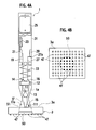
- the light source device 1 includes a light transmission unit 17 as illustrated with dashed lines therein, which is provided at a tip of a pen-shaped housing 31 having a tip 1a formed into a tapered cone shape or a tapered pyramid shape.
- the light transmission unit 17 is also formed into a tapered cone shape or a tapered pyramid shape, and includes an aperture at a tip portion thereof.
- the light transmission unit 17 is formed so as to transmit the light from the aperture to a predetermined position.
- the housing 31 is formed so as not to transmit the light.
- a light emitting diode 11 is provided inside the tip 1a, and a lens 13 is provided between this light emitting diode 11 and the pen tip 15.
- the light emitting diode 11 is covered with the lens 13, and the light emitting diode 11 and the lens 13 are integrally fitted to an insulative base 12.
- An anode terminal 14 and a cathode terminal 16 of the light emitting diode 11 protrude out of this base 12.
- the light emitting diode 11 and the lens 13 will be hereinafter collectively referred to as the light source unit.
- the light outputted from the light emitting diode 11 and passed through the lens 13 is transmitted through the light transmission unit 17 and the pen tip 15 and is outputted to outside.
- the anode terminal 14 of the light emitting diode 11 is connected to one end of a conductor 19.
- the other end of this conductor 19 electrically and movably contacts a conductive first mechanical contact member 21 which is disposed close to an inner wall of the light source device 1.
- the first mechanical contact member 21 is connected to a positive electrode (+) of a battery 25 through a resistor 23.
- a negative electrode (-) of the battery 25 is electrically connected to the housing 31 of the light source device 1 and, through the housing 31, is further electrically connected to a second mechanical contact member 29 fitted to the inner wall of the housing 31.
- the cathode terminal 16 of the light emitting diode 11 is connected to one end of a conductor 27.
- the other end 27a of the conductor 27 is bent perpendicularly and protrudes toward the vicinity of the second mechanical contact member 29.
- the other end 27a of the conductor 27 and the second mechanical contact member 29 collectively constitute a switch 35 as shown in a circuit diagram in Fig. 2B.
- the switch 35 is turned on when the other end 27a of the conductor 27 contacts the second mechanical contact member 29 as described later.
- the switch 35 is in an off state.
- One end of a compression spring 33 is fitted to the base 12.
- the other end of this compression spring 33 is fitted to a fixing portion which is provided inside the housing 31.
- the base 12 and the light source unit are pressed against the pen tip 15 by this compression spring 33, and the pen tip 15 is thereby pressed as well. In this way, an edge of the pen tip 15 slightly protrudes out of the aperture of the tip 1a.
- Fig. 2B is an equivalent circuit diagram of the light source device 1.
- the light source device 1 includes the light emitting diode 11, the resistor 23, the battery 25, and the switch 35 which are connected in series.
- the switch 35 includes the other end 27a of the conductor 27 and the second mechanical contact member 29.
- As the switch 35 is turned on an electric current flows from the positive electrode of the battery 25 to the negative electrode of the battery 25 through the resistor 23, the light emitting diode 11, and the switch 35.
- the light emitting diode 11 is turned on by this electric current and thereby irradiates the light.
- the display unit 3 includes pixel units 45 and photodetector units 47, which are disposed at respective intersections of a plurality of scan lines d1, d2, d3,..., and dn arranged in parallel and a plurality of signal lines e1, e2, e3,..., and em arranged in parallel.
- the pixel unit 45 displays an image signal supplied through the signal line onto the display screen.
- the photodetector unit 47 detects the light irradiated from the light source device 1 onto the display screen.
- Scan signals are sequentially outputted to the scan lines d by a scan line drive circuit 41.
- the image signals are outputted to the signal lines e by a signal line drive circuit 43.
- the pixel units 45 and the photodetector units 47 are arranged on a glass array substrate in a matrix of n pieces by m pieces as a whole.
- Each of the pixel units 45 includes a thin film transistor, a liquid crystal capacitor, and an auxiliary capacitor.
- Each of the photodetector units 47 includes a photoelectric transducer such as a photodiode, a charge storage capacitor, an amplifier transistor, a switch transistor, and a precharge transistor.
- the configuration of the pixel unit 45 is not limited only to the foregoing example, and the pixel unit 45 may include an electroluminescent (EL) element, for example.
- the configuration of the photodetector unit 47 is not limited only to the foregoing example, and the photodetector unit 47 may adopt any configuration as long as such a configuration can detect the light irradiated from the light source device 1 onto a display screen 3a of the display unit 3.
- Fig. 4A shows a state where the pen tip 15 of the light source device 1 is pressed against the display screen 3a of the display unit 3.
- the photodetector units 47 out of the pixel units 45 and the photodetector units 47 are illustrated at the bottom while the display screen 3a is illustrated at the top for the purpose of simplification.
- a clearance between the other end 27a of the conductor 27 and the second mechanical contact member 29 as shown in Fig. 2 is not bridged when the pen tip 15 of the light source device 1 is allowed to contact the display screen 3a of the display unit 3 and is pressed lightly against the display screen 3a. In this case, the switch 35 will not be turned on.
- the light from the light emitting diode 11 is irradiated onto the display screen 3a through the lens 13, the pen tip 15, and the light transmission unit 17.
- This light is irradiated onto the display screen 3a within a range indicated by chain lines 51 in the drawing, and a light receiving region 53 is thereby formed on the display screen 3a.
- the light receiving region 53 is illustrated in close proximity to a plurality of photodetector units 47 while the display screen 3a is illustrated away from the photodetector units 47 and from the light receiving region 53.
- planar positions of the photodetector units 47 are almost on the same plane as the display screen 3a. In the following, the light receiving region will be assumed to be formed on the display screen 3a.
- Fig. 4B is a top plan view of the display screen 3a on which the light is irradiated while disregarding the light source device 1.
- This drawing illustrates only the plurality of photodetector units 47, and the pixel units 45, the scan lines d, and the signal lines e are omitted.
- the light receiving region 53 on the display screen 3a where the light is irradiated is surrounded by a dashed line.
- the plurality of photodetector units 47 inside this light receiving region 53 detect the light irradiated from the light emitting diode 11 and output light detection signals independently.
- the photodetector units 47 existing inside the light receiving region 53 are illustrated in black.
- the light detection signals outputted by the plurality of photodetector units 47 as a result of detecting the light are supplied to the signal processing unit 5.
- the light reception and detection unit detects the light receiving region 53 based on the light detection signals
- the distance calculation unit calculates the distance between a tapered tip 17a of the light transmission unit 17 and the display screen 3a based on the light receiving region 53.
- the distance calculation unit includes an area calculation unit and an area-based distance calculation unit.
- the area calculation unit calculates the area of the light receiving region 53 based on the number of the photodetector units 47 which detect the light. In Fig. 4B, the number of the photodetector units 47 illustrated in black inside the light receiving region 53 is equal to 21 pieces.
- the area-based distance calculation unit calculates the distance between the tip 17a of the light transmission unit 17 and the display screen 3a based on this area.
- the area of the light receiving region 53 can be calculated by use of the number of the light detection signals from the plurality of the photodetector units 47.
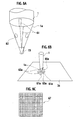
- Figs. 5A and 5B show a state where the pen tip 15 of the light source device 1 is pressed strongly against the display screen 3a by applying pressure greater than a predetermined amount.
- Fig. 5A and Fig. 5B correspond to Fig. 4A and Fig. 4B, respectively.
- the pen tip 15 when the pen tip 15 is pressed against the display screen 3a while applying the pressure greater than the predetermined amount, the pen tip 15 resists the force of the compression spring 33 moves into the aperture along the direction indicated by the arrow 111. Accordingly, the tip 17a of the light transmission unit 17 approaches the display screen 3a. In this case, the size of the light receiving region 53 formed on the display screen 3a by the light irradiated from the light emitting diode 11, that is, the area of the light receiving region 53 becomes smaller as compared to the case shown in Fig. 4A. Moreover, when the tip 17a of the light transmission unit 17 contacts the display screen 3a, the pen tip 15 cannot go further into the aperture and is therefore stopped at that position.
- the area of the light receiving region 53 formed on this display screen 3a is apparently smaller than the area shown in Fig. 4B.
- the number of the photodetector units 47 detecting the light and illustrated in black is reduced to 9 pieces.
- the area of the light receiving region 53 becomes large when the tip 17a of the light transmission unit 17 is far from the display screen 3a, and the area of the light receiving region 53 becomes small when the tip 17a of the light transmission unit 17 is close to the display screen 3a.
- the distance between the light transmission unit 17 and the display screen 3a has the above-described relation with the area of the light receiving region.
- the area of the light receiving region 53 by counting either the number of the photodetector units 47 outputting the light detection signals or the number of the light detection signals by use of the signal processing unit 5. Moreover, the distance between the tip 17a of the light transmission unit 17 and the display screen 3a is calculated based on this area.
- the relation between the counted number and the distance may be defined as a distance equal to 0 when the number ranges from 10 to 39 inclusive, a distance equal to 1 when the number ranges from 40 to 69 inclusive, a distance equal to 2 when the number ranges from 70 to 99 inclusive, and a distance equal to 3 when the number is equal to or greater than 100 or equal to or less than 9.
- Such rules may be stored in advance as data in a memory of the signal processing unit 5, for example. Then, the signal processing unit 5 calculates the distance by checking the actually counted number against the data.
- the distance data calculated by the signal processing unit 5 are supplied to the host processor 7.
- the host processor 7 changes the thickness of lines for drawing a figure such as a circle or a rectangle on the display screen in response to the distance data.
- the host processor 7 changes images such as characters, lines, figures or pictures displayed by the pixel units 45 in a position of an optical input on the display screen 3a in response to the above-described distance. For example, the host processor 7 changes the thickness of a line to a thin line, a thick line, a medium line, and the like in response to the above-described distance, and changes the color of the line to red, green, yellow or black. Meanwhile, the host processor 7 changes the thickness and the color of the line of a figure such as a circle or a rectangle, which is drawn around the position of the optical input on the display screen 3a, in response to the distance.
- the host processor 7 changes the thickness and the like of a line, which is drawn from the position of the optical input to a different position which is previously specified, in response to the above-described distance. To be more precise, the host processor 7 draws a thin line when the distance is long, and draws a thick line when the distance is short.
- the position calculation unit of the signal processing unit 5 calculates a position of irradiation of the light on the display screen, that is, a light receiving position based on the light receiving region 53 on the display screen 3a. To be more precise, firstly, the signal processing unit 5 sequentially scans the respective photodetector units 47 and receives the light detection signals. By performing this process, the position calculation unit can recognize the positions of the photodetector units 47 which transmit the light detection signals and obtain the position data of the plurality of photodetector units 47 located inside the light receiving region 53. It is easy for the signal processing unit 5 to calculate a center location of the light receiving region 53 or an arbitrary location inside the light receiving region 53.
- Center location data of the light receiving region 53 are supplied from the signal processing unit 5 to the host processor 7.
- the host processor 7 uses the center location data of the light receiving region 53 as a starting point for drawing the figure or the line such as the circle or the rectangle.
- the light detection signals from the respective photodetector units 47 are compared with a given thresholds in display unit 3 or the signal processing unit 5, and only the light detection signals greater than this threshold are formed into binary data.
- the signal processing unit 5 calculates the area, the distance, and the position as described above based on the light detection signals which are formed into the binary data.
- the perimeter of the light receiving region 53 may receive lower intensity of light as compared to the center and the boundary may become unclear. Accordingly, it is preferable to use the light detection signals in the form of the binary data so as to define the perimeter of the light receiving region 53 clearly.
- the light receiving region 53 is the region where light reception intensity, which is intensity of light that the display screen 3a receives from the light emitting diode 11, is greater than a given value. Accordingly, it is also possible to detect the light reception intensity depending on each of the photodetector units 47 and to define the light receiving region 53 based on distribution of the light reception intensity.
- the light reception and detection unit detects light reception intensity based on the light detection signals from the photodetector units 47. Then, the distance calculation unit calculates the distance between the light transmission unit and the display screen based on this light reception intensity, and the position calculation unit calculates the position of irradiation of the light on the display screen based on the light reception intensity.
- the light source device 1 when the tip of the light source device 1 is pressed against the display screen 3a, the light source device 1 changes the area of the light receiving region 53 in response to the degree of this pressure. Meanwhile, the signal processing unit 5 of the display device calculates the distance between the light transmission unit 17 of the light source device and the display screen 3a based on this light receiving region 53. In another case, the light source device 1 changes the light reception intensity on the display screen 3a in response to the degree of the pressure against the display screen 3a. Meanwhile, the signal processing unit 5 of the display device calculates the distance between the light transmission unit 17 and the display screen 3a based on this light reception intensity. By using this distance, it is possible to detect the degree of pressure of the light source device 1 against the display screen 3a.
- the light source unit does not output the light when the tip of the light source device 1 is not pressed against the display screen 3a. Therefore, it is possible to prevent malfunction attributable to outside environment light and to reduce power consumption by the light source unit by stopping the light detecting operation in the display unit.
- the area calculation unit calculates either the area of the region having the light reception intensity equal to or greater than the predetermined value or the area of the light receiving region. Meanwhile, the area-based distance calculation unit calculates the distance between the light transmission unit 17 and the display screen 3a based on this area. By calculating the area receiving the light as described above, it is possible to calculate the distance between the light transmission unit 17 and the display screen 3a easily.
- the position calculation unit calculates the position on the display screen where the light is irradiated, based either on the light reception intensity or on the light receiving region. In this way, it is possible to set the detected position easily to the starting point for drawing, for example, the line or the figure in accordance with the optical input from the light source device.
- Fig. 6A is an enlarged perspective view of the tip 1a in the pen-shaped light source device 1 which adopts a modified structure.
- the tip 1a of the light source device 1 in this drawing includes cross-shaped slits 61, and four small-diameter apertures 63 which are formed between the adjacent slits 61 in a facing manner while taking an intersection of the cross-shaped slits 61 as the center.
- the shape of the light to be projected on the display screen 3a when irradiating the light from the tip 1a of the light source device 1 is formed into a pattern including a cross-shaped slit form 61a and four dot forms 63a having relatively small diameters formed between the adjacent slits in a facing manner while taking the intersection of the cross-shaped form as the center as shown in Fig. 6B.
- the optical pattern is detected by the photodetector units 47 of the display unit 3, and is supplied to the signal processing unit 5 as the light detection signals.
- the signal processing unit 5 includes a storage unit, a check unit, and a judgment unit.
- the storage unit stores a matching pattern 67 as shown in Fig. 6C in advance, which coincides with the shape of the light irradiated from the cross-shaped slits 61 and the small-diameter apertures 63.
- the check unit checks the pattern based on the light detection signals detected by the photodetector units 47 against the matching pattern stored in the storage unit. The judgment unit judges that the light detection signals coinciding with the matching pattern in this check process as regular signals.
- the check unit reads the matching pattern 67 out of the storage unit, then converts the light detection signals supplied from the display unit 3 into binary data by use of the given threshold, and checks this optical pattern converted into the binary data against the matching pattern 67.
- the judgment unit performs pattern matching to judge that the optical pattern detected by the display unit 3 is the genuine optical pattern outputted form the light source device 1, and that the optical pattern is not affected by other light components coming from outside.
- the signal processing unit 5 calculates the position of this optical pattern on the display screen 3a and the distance between the light transmission unit 17 and the display screen 3a as described above, and supplies the position data and the distance data to the host processor 7.
- the host processor 7 performs the variety of processing as described above based on the position data and the distance data.
- the light source device 1 irradiates the light including the cross-shaped slits and the small-diameter dot shapes onto the display screen.
- the check unit of the signal processing unit 5 checks the optical pattern including the cross-shaped slits and the small-diameter dot shapes detected by the photodetector units 47 against the matching pattern 67 stored in advance in the storage unit, and the judgment unit judges that the light detection signals of this optical pattern represent the genuine signals when the optical pattern coincides with the matching pattern 67.
- the above-described artificial optical pattern does not occur in nature or is not created by the environment light. Therefore, the optical pattern can be judged accurately. In this way, the display device can perform the variety of processing properly without causing malfunction attributable to the influence of the environment light from outside.
- the above-described optical pattern provides the four small-diameter apertures 63 so as to project the four small-diameter optical dot shapes 63a.
- the number of the apertures 63 is not limited only to four, and the number of the apertures may be an arbitrary amount equal to or more than one.
- the shape of the slits 61 is not limited only to the cross shape.
- the light reception intensity of the optical pattern from the light source device 1 varies depending on rotation, inclination, and the degree of pressure of the light source device 1. Accordingly, it is also possible to obtain information concerning the rotation, the inclination, and the degree of pressure of the light source device 1 by performing pattern matching with such deformation taken into consideration.
- a timing controller 73 and a power source 71 subject to on and off control by this timing controller 73 are added to this device as shown in Fig. 7.
- the timing controller 73 performs synchronous control of operations of the plurality of photodetector units 47 in the display unit 3 and operations of light irradiation by a light source device 10.
- the photodetector units detect the light reception intensity or the light receiving region on the display screen synchronously with the operations of the photodetector units 47.
- the light source device 10 uses the power source 71 instead of the battery 25.
- a switch 71a is connected to an output line of the power source 71, and electricity is supplied from the power source 71 to the light source device 10 through this switch 71a.
- On and off operations of the switch 71 are controlled by the timing controller 73.
- Other constitutions and operations in Fig. 7 are similar to those described in the foregoing embodiments. The same constituents are designated by the same reference numerals.
- the timing controller 73 supplies an image capturing control signal to the display unit 3 in order to operate the plurality of photodetector units 47 in the display unit 3, generates a switch control signal which is synchronous with this image capturing control signal, and controls on and off of the switch 71a by use of this switch control signal.
- the timing controller 73 turns the light source device 10 on and off by means of the on and off operations of the switch 71.
- the timing controller 73 supplies a light-on flag or a light-off flag indicating a condition of the light source device 10 to the signal processing unit 5.
- the signal processing unit 5 can identify that the light detection signals are attributable to the outside environment light. Accordingly, it is possible to prevent malfunction attributable to the outside environment light and the like properly by ignoring the relevant light detection signals. Meanwhile, if the signal processing unit 5 receives the light detection signals from the photodetector units 47 of the display unit 3 when the light source device 10 is irradiating the light, i.e. when the light-on flag is outputted from the timing controller 73 to the signal processing unit 5, the signal processing unit 5 can identify that the light detection signals are the regular light from the pen tip 15 of the light source device 10.
- one frame cycle is equivalent to a time period required for sequentially scanning the plurality of the photodetector units 47 just for one round. This time period is also equivalent to a period for obtaining one piece of image capturing data.
- the light source device 10 is operated to repeat light-on and light-off in the double cycle of the frame synchronization as shown in light-off n, light-on n, light-off n+1, and light-on n+1.
- This operation is achieved by turning the switch 71a of the power source 71 on and off in accordance with the switch control signal from the timing controller 73 and by supplying the electricity from the power source 71 to the light source device 10 in accordance with the on and off operation.
- the plurality of pixel units 45 alternate liquid crystal display and blanking synchronously with operations to turn the light source device 10 on and off by the image capturing control signal from the timing controller 73, and the plurality of photodetector units 47 alternate exposure (light detection), data transfer, and initial charge storage.
- binary image data (such as F(2n)) representing the light detection signals in the light-off state and binary image data (such as F(2n+1)) representing the light detection signals in the light-on state are alternately supplied to the signal processing unit 5.
- an operating unit of the signal processing unit 5 calculates a logical product of a logical negation value (not F(2n)) of the binary image data in the light-off state and the binary image data (F(2n+1)) in the light-on state for each pixel.
- the logical product becomes equal to 1 only when a piece of the binary image data F(2n) in the light-off state is equal to 0 (black) representing that the light is not detected while a piece of the binary image data F(2n+1) in the light-on state is equal to 1 (white) representing that the light is detected.
- the judgment unit of the signal processing unit judges that the light detection signal is the regular light detection signal attributable to the genuine light from the light source device 10 only in the foregoing case.
- a truth table in Fig. 9 will be described in detail starting from an upper part of the table. Firstly, when the piece of the binary image data F(2n) in the light-off state is equal to 0 (black) representing that the light is not detected and the piece of the binary image data F(2n+1) in the light-on state is also equal to 0 (black), the logical product of the both values (not F(2n) and F(2n+1)) is equal to 0 (black). This result indicates that the light is not detected.
- the judgment unit of the signal processing unit 5 judges that the light detection signal from the photodetector unit 47 is the regular light detection signal attributable to the genuine light from the light source device 10 only in this case.
- the piece of the binary image data F(2n) in the light-off state is equal to 1 (white) and the piece of the binary image data F(2n+1) in the light-on state is equal to 0 (black)
- the above-described logical product is equal to 0 (black).
- the piece of the binary image data F(2n) in the light-off state is equal to the logical value 1 indicating that the light is detected.
- This logical value 1 is brought about as a result of malfunction attributable to the outside environment light or the like.
- the logical product is set to 0 so as to detect such malfunction.
- the phenomenon that the piece of the binary image data F(2n+1) in the light-on state is equal to the logical value 0 indicating that the light is not detected in spite of the light-on state means that the light from the light source device 10 is nor irradiated on the position where the photodetector unit 47 relevant to this light detection is located.
- this phenomenon means that the relevant photodetector unit 47 is located outside the light receiving region 53 shown in Fig. 4A to Fig. 5B, or that the photodetector unit 47 fails to detect the light from the light source device 10 although the photodetector unit 47 is located inside the light receiving region 53.
- the piece of the binary image data F(2n) in the light-off state is equal to 1 (white) and the piece of the binary image data F(2n+1) in the light-on state is also equal to 1 (white)
- the above-described logical product is equal to 0 (black).
- the piece of the binary image data F(2n) in the light-off state is equal to the logical value 1 indicating that the light is detected.
- This logical value 1 is brought about as a result of malfunction attributable to the outside environment light or the like.
- the logical product is set to 0 so as to detect such malfunction.
- the timing controller 73 synchronously controls the operations of the photodetector units 47 in the display unit 3 and the operations of light irradiation by the light source device 10, and the light reception and detection unit detects either the light reception intensity or the light receiving region on the display screen synchronously with the operations of the photodetector units 47.
- the photodetector unit 47 erroneously detects the outside environment light and the like when the light source device 10 does not irradiate the light, it is possible to judge such malfunction easily and thereby to prevent malfunction attributable to the outside environment light properly.
- the timing controller 73 blinks the light source device 10 synchronously with the operations of the photodetector units 47. In this way, even if the photodetector unit erroneously detects the outside environment light and the like when the light source device 10 does not irradiate the light, for example, it is possible to judge such malfunction easily and thereby to prevent malfunction attributable to the outside environment light properly.
- the timing controller 73 blinks the light source device 10 synchronously with the double cycle of the frame synchronization. In this way, even if the photodetector unit 47 erroneously detects the outside environment light and the like when the light source device 10 does not irradiate the light, it is possible to judge such malfunction easily and thereby to prevent malfunction attributable to the outside environment light properly.
- the operating unit of the signal processing unit calculates the logical product of the logical negation signal not F(2n) of the binary image data F(2n) in the light-on state and the binary image data F(2n+1) in the light-on state, which are alternately and continuously outputted. By using the result of calculation, it is possible to prevent malfunction attributable to the outside environment light properly.
- the power source 71 and the switch 71a are provided and the switch 71a is subjected to the on and off control by use of a power source switch control signal from the timing controller 73 in order to blink the light source device 10.
- the display device of the invention is not limited only to the above-described configuration.
- the light source 1 shown in Figs. 2A is it also possible to provide a switch on a path for supplying electricity from the battery 25 to the light emitting diode 11, and to subject this switch to the on and off control by use of a control signal from the timing controller 73 in order to blink the light emitting diode 11.
- the signal outputted from each of the photodetector units 47 is defined as the light detection signal provided solely for indicating detection of the light.
- an image is formed by gathering the plurality of output signals from these photodetector units 47, it is also apply image capturing signals instead of the light detection signals.
- the light detection signal is compared with the given threshold by the display unit 3 or the signal processing unit 5 and is outputted as the binary data, it is also possible to set the light detection signal to binary data.
Landscapes
- Engineering & Computer Science (AREA)
- General Engineering & Computer Science (AREA)
- Theoretical Computer Science (AREA)
- Human Computer Interaction (AREA)
- Physics & Mathematics (AREA)
- General Physics & Mathematics (AREA)
- Position Input By Displaying (AREA)
- Devices For Indicating Variable Information By Combining Individual Elements (AREA)
- Liquid Crystal (AREA)
- Liquid Crystal Display Device Control (AREA)
Applications Claiming Priority (2)
| Application Number | Priority Date | Filing Date | Title |
|---|---|---|---|
| JP2004127161A JP4469650B2 (ja) | 2004-04-22 | 2004-04-22 | 光入力機能付き表示装置、表示装置および光源装置 |
| JP2004127161 | 2004-04-22 |
Publications (2)
| Publication Number | Publication Date |
|---|---|
| EP1589408A2 true EP1589408A2 (fr) | 2005-10-26 |
| EP1589408A3 EP1589408A3 (fr) | 2008-04-09 |
Family
ID=34935444
Family Applications (1)
| Application Number | Title | Priority Date | Filing Date |
|---|---|---|---|
| EP05008618A Withdrawn EP1589408A3 (fr) | 2004-04-22 | 2005-04-20 | Dispositif d'affichage avec une fonction d'entrée optique |
Country Status (6)
| Country | Link |
|---|---|
| US (1) | US20050237313A1 (fr) |
| EP (1) | EP1589408A3 (fr) |
| JP (1) | JP4469650B2 (fr) |
| KR (1) | KR100684252B1 (fr) |
| CN (1) | CN1333328C (fr) |
| TW (1) | TWI321287B (fr) |
Cited By (3)
| Publication number | Priority date | Publication date | Assignee | Title |
|---|---|---|---|---|
| EP2560077A4 (fr) * | 2010-04-16 | 2014-03-19 | Sharp Kk | Dispositif d'affichage d'entrée, dispositif d'entrée et procédé de commande de dispositif d'entrée |
| EP2343629A3 (fr) * | 2010-01-08 | 2015-01-21 | Integrated Digital Technologies, Inc. | Stylet et système d'entrée tactile |
| EP2590059A3 (fr) * | 2011-11-04 | 2016-02-24 | Samsung Electronics Co., Ltd. | Procédé et système pour reconnaître un point tactile et appareil d'affichage |
Families Citing this family (25)
| Publication number | Priority date | Publication date | Assignee | Title |
|---|---|---|---|---|
| US7298367B2 (en) * | 2003-11-25 | 2007-11-20 | 3M Innovative Properties Company | Light emitting stylus and user input device using same |
| US20050110777A1 (en) * | 2003-11-25 | 2005-05-26 | Geaghan Bernard O. | Light-emitting stylus and user input device using same |
| US7348969B2 (en) * | 2003-12-30 | 2008-03-25 | 3M Innovative Properties Company | Passive light stylus and user input device using same |
| CN101546371B (zh) * | 2008-03-28 | 2013-05-08 | 爱国者数码科技有限公司 | 力传感控制的编码识别装置 |
| US20100294574A1 (en) * | 2009-05-21 | 2010-11-25 | Eric Chen | LED stylus pen |
| US8519984B2 (en) | 2009-08-20 | 2013-08-27 | Acer Incorporated | Input device and display system having the same |
| WO2011068024A1 (fr) * | 2009-12-03 | 2011-06-09 | シャープ株式会社 | Dispositif d'affichage à fonction de détection de position et système de détection de position d'entrée |
| CN102235860B (zh) * | 2010-04-20 | 2014-09-03 | 原相科技股份有限公司 | 测距装置、立体影像感测装置以及光学式触控系统 |
| US20130044465A1 (en) * | 2010-04-30 | 2013-02-21 | Nokia Corporation | Method and apparatus for providing user input |
| CN102314260A (zh) * | 2010-06-29 | 2012-01-11 | 宏碁股份有限公司 | 光学式输入装置及具有该光学式输入装置的显示系统 |
| JP5796733B2 (ja) * | 2011-03-23 | 2015-10-21 | ソニー株式会社 | 光信号出力装置、信号処理装置、信号処理方法、信号処理システム、撮像装置、プロジェクタ、およびプログラム |
| TW201317839A (zh) * | 2011-10-25 | 2013-05-01 | Au Optronics Corp | 觸控筆、觸控顯示系統以及觸控顯示方法 |
| TWI447611B (zh) * | 2011-12-20 | 2014-08-01 | Au Optronics Corp | 三維互動顯示裝置及其操作方法 |
| CN104412209A (zh) * | 2012-09-07 | 2015-03-11 | 松下知识产权经营株式会社 | 显示装置以及显示控制系统 |
| US9423892B2 (en) * | 2012-11-15 | 2016-08-23 | Brother Kogyo Kabushiki Kaisha | Information input device |
| JP6098328B2 (ja) * | 2013-04-18 | 2017-03-22 | ブラザー工業株式会社 | 情報入力装置 |
| KR20150004138A (ko) | 2013-07-02 | 2015-01-12 | 삼성디스플레이 주식회사 | 위치 감지 시스템 및 그 구동 방법 |
| KR101478659B1 (ko) * | 2013-10-10 | 2015-01-02 | 재단법인대구경북과학기술원 | 광원 제어 기능이 구비된 터치 스크린용 전자펜 동작 시스템 및 그 방법 |
| CN203799341U (zh) * | 2014-04-03 | 2014-08-27 | 致伸科技股份有限公司 | 被动式触控笔 |
| CN104484064B (zh) | 2014-12-30 | 2018-04-27 | 合肥鑫晟光电科技有限公司 | 用于触摸显示屏的主动笔、触摸显示屏及触控输入系统 |
| CN104932692B (zh) * | 2015-06-24 | 2017-12-08 | 京东方科技集团股份有限公司 | 三维触摸感测方法、三维显示设备、可穿戴设备 |
| JP6642400B2 (ja) * | 2016-12-08 | 2020-02-05 | 株式会社ジェイテクト | 光検知装置及び設備管理システム |
| CN107678600A (zh) * | 2017-10-25 | 2018-02-09 | 京东方科技集团股份有限公司 | 数位板、信号发射装置、数位板装置及其控制方法 |
| CN116125693B (zh) * | 2022-12-30 | 2025-10-24 | 山东蓝贝思特教装集团股份有限公司 | 一种光书写笔、电子纸及方法 |
| JP7440683B1 (ja) | 2023-03-23 | 2024-02-28 | レノボ・シンガポール・プライベート・リミテッド | 入力デバイス及び情報処理システム |
Family Cites Families (18)
| Publication number | Priority date | Publication date | Assignee | Title |
|---|---|---|---|---|
| AT361608B (de) * | 1979-01-31 | 1981-03-25 | Kretztechnik Gmbh | Verfahren zum markieren bzw. auswerten oder ausmessen von schirmbildern, insbesondere von nach dem ultraschall-impuls-echoverfahren er- zeugten schnittbildern und geraet zur durch- fuehrung dieses verfahrens |
| JPS56158381A (en) * | 1980-05-12 | 1981-12-07 | Suwa Seikosha Kk | Liquid crystal display unit |
| US4705942A (en) * | 1985-12-26 | 1987-11-10 | American Telephone And Telegraph Company, At&T Bell Laboratories | Pressure-sensitive light pen |
| US5649023A (en) * | 1994-05-24 | 1997-07-15 | Panasonic Technologies, Inc. | Method and apparatus for indexing a plurality of handwritten objects |
| JPH08147097A (ja) * | 1994-11-18 | 1996-06-07 | Csk Corp | ペン型ポインティングデバイス |
| GB9516441D0 (en) * | 1995-08-10 | 1995-10-11 | Philips Electronics Uk Ltd | Light pen input systems |
| JP3522399B2 (ja) * | 1995-08-11 | 2004-04-26 | シャープ株式会社 | 情報処理装置 |
| AU753931B2 (en) * | 1998-04-03 | 2002-10-31 | Image Guided Technologies, Inc. | Wireless optical instrument for position measurement and method of use therefor |
| KR20000012402A (ko) * | 1999-12-02 | 2000-03-06 | 박희정 | 라이트 펜 마우스 장치 |
| KR20000024146A (ko) * | 2000-01-25 | 2000-05-06 | 함종훈 | 펜형 이미지 센서 마우스 |
| KR100349031B1 (ko) * | 2000-12-15 | 2002-08-17 | 핑거시스템 주식회사 | 펜형 광 마우스 장치 |
| JP2004516542A (ja) * | 2000-12-15 | 2004-06-03 | フィンガー システム インク. | ペン型光マウス装置及びペン型光マウス装置の制御方法 |
| KR100442908B1 (ko) * | 2001-07-23 | 2004-08-02 | 핑거시스템 주식회사 | 펜형 광마우스의 구동 방법 |
| CN2509647Y (zh) * | 2001-10-29 | 2002-09-04 | 仁宝电脑工业股份有限公司 | 具有照明功能的触控笔 |
| AU2003213188A1 (en) * | 2002-02-20 | 2003-09-09 | Adiel Abileah | Light sensitive display |
| GB0213215D0 (en) * | 2002-06-08 | 2002-07-17 | Lipman Robert M | Computer navigation |
| CN2577353Y (zh) * | 2002-10-14 | 2003-10-01 | 联想(北京)有限公司 | 激光触控笔 |
| KR100438846B1 (ko) | 2003-10-07 | 2004-07-06 | 함종훈 | 펜형 마우스 장치 |
-
2004
- 2004-04-22 JP JP2004127161A patent/JP4469650B2/ja not_active Expired - Fee Related
-
2005
- 2005-04-01 US US11/095,512 patent/US20050237313A1/en not_active Abandoned
- 2005-04-06 TW TW094110871A patent/TWI321287B/zh not_active IP Right Cessation
- 2005-04-20 EP EP05008618A patent/EP1589408A3/fr not_active Withdrawn
- 2005-04-21 CN CNB2005100661857A patent/CN1333328C/zh not_active Expired - Fee Related
- 2005-04-22 KR KR1020050033721A patent/KR100684252B1/ko not_active Expired - Fee Related
Cited By (3)
| Publication number | Priority date | Publication date | Assignee | Title |
|---|---|---|---|---|
| EP2343629A3 (fr) * | 2010-01-08 | 2015-01-21 | Integrated Digital Technologies, Inc. | Stylet et système d'entrée tactile |
| EP2560077A4 (fr) * | 2010-04-16 | 2014-03-19 | Sharp Kk | Dispositif d'affichage d'entrée, dispositif d'entrée et procédé de commande de dispositif d'entrée |
| EP2590059A3 (fr) * | 2011-11-04 | 2016-02-24 | Samsung Electronics Co., Ltd. | Procédé et système pour reconnaître un point tactile et appareil d'affichage |
Also Published As
| Publication number | Publication date |
|---|---|
| KR20060047443A (ko) | 2006-05-18 |
| CN1690939A (zh) | 2005-11-02 |
| KR100684252B1 (ko) | 2007-02-20 |
| JP2005309859A (ja) | 2005-11-04 |
| EP1589408A3 (fr) | 2008-04-09 |
| TWI321287B (en) | 2010-03-01 |
| JP4469650B2 (ja) | 2010-05-26 |
| US20050237313A1 (en) | 2005-10-27 |
| CN1333328C (zh) | 2007-08-22 |
| TW200602958A (en) | 2006-01-16 |
Similar Documents
| Publication | Publication Date | Title |
|---|---|---|
| EP1589408A2 (fr) | Dispositif d'affichage avec une fonction d'entrée optique | |
| US8665223B2 (en) | Display device and method providing display contact information based on an amount of received light | |
| US8749527B2 (en) | Input device | |
| US8610670B2 (en) | Imaging and display apparatus, information input apparatus, object detection medium, and object detection method | |
| US7176905B2 (en) | Electronic device having an image-based data input system | |
| WO2017005147A1 (fr) | Substrat de réseau, panneau d'affichage et appareil d'affichage l'ayant, et procédé de pilotage associé | |
| US20170199606A1 (en) | Display panel, display apparatus having the same, and driving method thereof | |
| CN101135949B (zh) | 成像和显示设备、信息输入设备、物体检测方法 | |
| JP2004348739A (ja) | 光学的にクリックを検出する方法およびシステム | |
| KR20100027988A (ko) | 정보 입력 장치, 정보 입력 방법, 정보 입출력 장치 및 정보 입력 프로그램 | |
| JP2009064074A (ja) | 入力装置 | |
| CN107566628B (zh) | 显示模组及其显示方法、终端 | |
| US20220086378A1 (en) | Electronic device and imaging method thereof | |
| US20230043020A1 (en) | Image scanning device and image scanning method | |
| CN210721505U (zh) | 电子装置 | |
| CN107958650B (zh) | 生物感测模组及其驱动电路、电子设备 | |
| JP2012243201A (ja) | 入力機能付表示装置 | |
| US11270097B2 (en) | Electronic device having fingerprint sensing function and fingerprint sensing method | |
| JP4270247B2 (ja) | 表示撮像装置、物体検出プログラムおよび物体の検出方法 | |
| CN107958194B (zh) | 光电传感装置及电子设备 | |
| JP4457163B1 (ja) | 表示装置 | |
| US20120250033A1 (en) | Optical sensor circuit, two-dimensional coordinate detection apparatus, information processing apparatus, and method of refresh-driving optical sensor element | |
| JPWO2014017039A1 (ja) | 情報読取装置 | |
| US11567621B2 (en) | Display panel, mobile terminal and method for controlling mobile terminal | |
| JP2006216087A (ja) | 情報表示入力装置 |
Legal Events
| Date | Code | Title | Description |
|---|---|---|---|
| PUAI | Public reference made under article 153(3) epc to a published international application that has entered the european phase |
Free format text: ORIGINAL CODE: 0009012 |
|
| 17P | Request for examination filed |
Effective date: 20050420 |
|
| AK | Designated contracting states |
Kind code of ref document: A2 Designated state(s): AT BE BG CH CY CZ DE DK EE ES FI FR GB GR HU IE IS IT LI LT LU MC NL PL PT RO SE SI SK TR |
|
| AX | Request for extension of the european patent |
Extension state: AL BA HR LV MK YU |
|
| PUAL | Search report despatched |
Free format text: ORIGINAL CODE: 0009013 |
|
| AK | Designated contracting states |
Kind code of ref document: A3 Designated state(s): AT BE BG CH CY CZ DE DK EE ES FI FR GB GR HU IE IS IT LI LT LU MC NL PL PT RO SE SI SK TR |
|
| AX | Request for extension of the european patent |
Extension state: AL BA HR LV MK YU |
|
| AKX | Designation fees paid | ||
| STAA | Information on the status of an ep patent application or granted ep patent |
Free format text: STATUS: THE APPLICATION IS DEEMED TO BE WITHDRAWN |
|
| 18D | Application deemed to be withdrawn |
Effective date: 20081010 |
|
| REG | Reference to a national code |
Ref country code: DE Ref legal event code: 8566 |