EP1589313A2 - Hilfsmittel für Jäger - Google Patents
Hilfsmittel für Jäger Download PDFInfo
- Publication number
- EP1589313A2 EP1589313A2 EP05290851A EP05290851A EP1589313A2 EP 1589313 A2 EP1589313 A2 EP 1589313A2 EP 05290851 A EP05290851 A EP 05290851A EP 05290851 A EP05290851 A EP 05290851A EP 1589313 A2 EP1589313 A2 EP 1589313A2
- Authority
- EP
- European Patent Office
- Prior art keywords
- mirror
- arm
- plane
- symmetry
- hunter
- Prior art date
- Legal status (The legal status is an assumption and is not a legal conclusion. Google has not performed a legal analysis and makes no representation as to the accuracy of the status listed.)
- Granted
Links
Images
Classifications
-
- F—MECHANICAL ENGINEERING; LIGHTING; HEATING; WEAPONS; BLASTING
- F41—WEAPONS
- F41A—FUNCTIONAL FEATURES OR DETAILS COMMON TO BOTH SMALLARMS AND ORDNANCE, e.g. CANNONS; MOUNTINGS FOR SMALLARMS OR ORDNANCE
- F41A21/00—Barrels; Gun tubes; Muzzle attachments; Barrel mounting means
- F41A21/32—Muzzle attachments or glands
- F41A21/325—Mountings for muzzle attachments
-
- F—MECHANICAL ENGINEERING; LIGHTING; HEATING; WEAPONS; BLASTING
- F41—WEAPONS
- F41A—FUNCTIONAL FEATURES OR DETAILS COMMON TO BOTH SMALLARMS AND ORDNANCE, e.g. CANNONS; MOUNTINGS FOR SMALLARMS OR ORDNANCE
- F41A35/00—Accessories or details not otherwise provided for
-
- F—MECHANICAL ENGINEERING; LIGHTING; HEATING; WEAPONS; BLASTING
- F41—WEAPONS
- F41C—SMALLARMS, e.g. PISTOLS, RIFLES; ACCESSORIES THEREFOR
- F41C27/00—Accessories; Details or attachments not otherwise provided for
Definitions
- the present invention relates to the design and realization of a device of accessory equipment for hunter. It aims to improve the safety conditions of hunting in collective practice while facilitating the aim of the hunter.
- Hunting usually consists of watching and chasing animals to kill them as part of a hobby, or out of necessity.
- the hunters are led to place themselves along an imaginary line, called the line of battue, while keeping between them distances which are supposed to limit the risk that an animal could pass between two hunters.
- hunters must be careful not to hurt each other.
- hunters limit their fire in an area called a safety zone between two lines of sight that the hunters impose on both sides of a plane perpendicular to the line of battue.
- An accessory equipment apparatus for fighter designed to improve the safety conditions of the hunting in collective practice, including making it easier to each hunter to set limits beyond which a shot targeted towards a passing animal in his shooting range could be dangerous by making him run the risk of hurting a hunter neighbour.
- the apparatus comprises at least one mirror reflective whose axis of reflection is orientable in a plane horizontally, with respect to a vertical plane of symmetry defined by a support on which it is mounted, between two extreme positions defining between them an angular interval corresponding to a safe shooting zone on either side of a line of sight median located in said plane of symmetry.
- the apparatus according to the invention allows a hunter to choose more easily landmarks to limit his area safe shooting.
- hunters take natural landmarks from those around them, such as trees. or bushes. Ideally, hunters choose these markers in two symmetrically inclined directions of about thirty degrees from the beat line.
- the safety zone in which the hunters limit their aim has an angle of opening that is complementary to those in which the hunters do not allow themselves to shoot.
- the apparatus according to the invention allows the hunter to choose your natural landmarks by looking in the extension of the mirror placed in one or other of the two extreme positions.
- the apparatus according to the invention allows a hunter to anticipate the passage of an animal before the animal enters the safe area the hunter has defined himself, without however, lose his line of sight, thanks to the presence of the mirror. Of therefore, the chances of touching an animal are increased.
- the apparatus comprises means for place the mirror in one or the other of two symmetrical positions remote from a user hunter of said apparatus in firing position.
- the device is easier to use for the hunter and the mirror placed at a distance gives him a broader vision what is going on beyond his safe shooting range.
- the latter is designed to be fixed on the gun of a rifle.
- the apparatus according to the invention comprises advantageously a support plate which has means of fixing on the barrel of a rifle and on which an arm is mounted pivoting between said two symmetrical positions, said mirror being mounted at one end of said arm.
- the plane of symmetry is vertical and passes through the barrel axis of the rifle on which the platinum bracket is attached, and the arm is a way to place the mirror remote from a user hunter of said apparatus in firing position.
- the means allowing to place the mirror in one or the other of two positions symmetrical consist of two partial housing imprints of the arms that are arranged symmetrically with respect to the plane of symmetry in said platen, providing a temporary lock of the orientation of the arm, and therefore of the mirror, according to the two positions extremes.
- the device allows the hunter to choose more conveniently the natural landmarks following the limiting directions between which the hunter will allow himself to shoot: It is enough for him to use the apparatus according to the invention by placing the barrel of its rifle right in front of him (perpendicular to the beat line), then looking in the extension of the arm supporting the mirror, placed in either of the two footprints, to find both natural elements of its environment to consider to limit his range of fire.
- Each of the cavities is advantageously arranged in the plate in such a way that the arm is oriented angle of sixty degrees from the plane of symmetry.
- the device responds to the most common choice of hunters, this choice being to consider a safe shooting angle of sixty degrees of both sides of the barrel of their rifle when they direct it right in front of them.
- a third impression is advantageously provided in the plate following the plane of symmetry, so as to position the arm and temporarily lock the position of the arm in the extension of the axis of the barrel of the rifle. This allows you to tidy up the device in a space smaller than that which would have to be provided if the device did not allow to fold the arm in one direction parallel to that of the barrel.
- the arm comprises two tubes mounted telescopically sliding one into the other and a ring of temporary fixing of these tubes relative to each other.
- the hunter thus has the opportunity to reduce the length of the arm.
- This realization allows then to store the device in a space more small if the arm was not telescopic.
- the telescopic arm, in the folded position has a length less than the length of the barrel.
- the mirror is rotatably mounted around the axis of the arm, so that the hunter can modify the orientation of the reflection axis of the mirror in a vertical plane.
- a hunting accessory according to the invention, it is made to be fixed temporarily in the soil.
- the apparatus according to the invention advantageously comprises this effect a cane support two mirrors that are mounted pivoting by their edge on the side wall of said rod to one of its ends.
- the plane of symmetry considered is that of the cane following its length, passing in the middle.
- the apparatus comprises two shims, each of the shims being preferentially attached to the back of each mirrors.
- the wedges limit the orientation of the mirrors in two extreme positions defining between them an angular interval corresponding to a zone fired safely on both sides of a median line of sight located in said plane of symmetry.
- the cane has two halves symmetrical made to be separated and collected according to the plane of symmetry, each of the two halves presenting one of the two mirrors.
- the two symmetrical halves of cane constitute the means for placing the mirrors in one or the other of two symmetrical positions at a distance from the hunter.
- the hunter can use this accessory thus produced according to the invention to determine its firing range: It separates the two halves symmetrical trunk, by pressing the foot of each half trunk to his right and to his left taking care of good arrange the two halves symmetrically with respect to the plane of symmetry, perpendicular to the beat line. Then he rotates the two mirrors until their wedge comes up against the wall lateral of each of the trunk halves. It can easily choose the boundaries of your firing zone by taking two points elements of his environment each located in the extension of the plans of the mirrors.
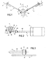
- the apparatus according to the invention is designed to be attached to the barrel 1 of a shotgun 2, such as that which is illustrated in Figure 6.
- the butt of the rifle 2 is represented decorated incidentally a dog's head, which may correspond to the head the hunter's dog user of this rifle. It must be understood that the butt of the rifle could be decorated with another head of dog, or not be decorated at all.
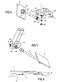
- the apparatus according to the invention is attached to the barrel of a rifle by means of a plate 4 that the device comprises ( Figure 2).
- the plate 4 has two jaws 41 and 42 whose tightening secures the device to the barrel 1. Both jaws are shown clearly in Figures 2, 4 and 5.
- the jaw 42 is fixed and the jaw 41 is movable.
- Platinum 4 has a screw 7 which allows to bring the jaw 41 of the jaw 42 and thus strongly seize the barrel 1 of the rifle between two jaws 41 and 42, as shown in FIG. head of the screw is knurled to be turned by hand more easily and his body is screwed into a tapped channel in the turntable 4, shown in FIG.
- the apparatus has at least one reflecting plane mirror 3 whose axis of reflection X is orientable in a horizontal plane, with respect to a plane of vertical symmetry defined by the plate 4, supporting an arm 6 at the end of which is mounted the mirror 3.
- the plate 4 thus supports indirectly the mirror 3.
- the freedom of orientation of the axis of mirror reflection 3 extends between two extreme positions symmetrical.
- FIG. 1 shows the two extreme positions of the mirror X axis of reflection.
- the two extreme positions of the X axis correspond respectively to two extreme positions of the mirror.
- One of the extreme positions of the mirror 3 is represented in solid lines and the other extreme position of the mirror 3 is shown in dotted lines.
- the two extreme positions of the plane of the mirror define between them an angular interval 5, represented in FIG. 1, corresponding to a safe shooting zone on either side a median line of sight D which is located in said plane of symmetry.
- the arm 6 is pivoted by one of its ends on the plate 4 between the two extreme positions shown in Figure 1, the mirror 3 being mounted at the other end of the arm 6.
- the arm 6 constitutes a means for placing the mirror 3 to distance from a hunter.
- it comprises two tubes 61 and 62 mounted telescopically sliding one into the other and a ring 63 temporarily fixing the position of these tubes relative to each other to the other.
- the hunter can vary the length of the arm 6 to move more or less away the mirror 3.
- This telescopic arm construction offers the advantage of ability to store the device in a smaller space than the one it would be necessary if the arm was not telescopic.
- the folded telescopic arm has a length which is less than that of the barrel, so that the whole consisting of the rifle and the device occupies a storage length identical to that originally planned for the rifle alone.
- two impressions 43 and 44 are arranged symmetrically with respect to the plane of symmetry in the support plate 4 (FIGS. 4 and 5).
- the two prints 43 and 44 are realized in such a way that the arm 6 is partially lodged therein.
- a knurled knob 45 screwed onto a threaded rod 16 crossing the end arm and plate ( Figure 4), allows, like a nut, to hold the arm in position in one or the other of the impressions 43 or 44.
- Each of the fingerprints 43 and 44 is provided in the platen 4 so that the arm 6 can be oriented advantageously at an angle of sixty degrees to the line of sight D, on both sides of the barrel 1 of the rifle 2.
- a third impression 46 is formed in the plate 4 following said plane of symmetry ( Figure 5). This third impression allows to place the arm 6 in the same plane as that of the rifle, by example to store it, as shown in Figure 6.
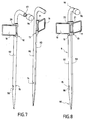
- FIG. 3 represents the mounting means of the mirror 3 to the end of the arm 6.
- the mirror 3 is mounted free to rotate about the axis of the 6.
- a tip 8 comprising a ring forming a shoulder 81, is attached to the end of the arm 6 so that the shoulder 81 is set back relative to the end of the arm 6.
- the maintaining the tip 8 on the arm 6 is done by insertion and fixation, by any known means, the end of the arm 6 (end of the tube 62 in FIG. 3) in a housing formed in the end piece 8 its axis.
- the mirror 3 has, on the opposite side to the one that is reflective and in the axis of reflection X, a ring integral 31 (also shown in Figure 4) whose diameter internal is equal to the game close to that of the tip 8 to be able to be slidably mounted around the latter at the end of the arm 6.
- the inner diameter of ring 31 is also slightly lower to that of the ring forming the shoulder 81 so that the ring 31 take support against him.
- the ring forming the shoulder 81 thus constitutes a stop for the ring 31 integral with the mirror 3.
- the ring 31 and the mirror 3 can rotate freely around the axis of the arm 6.
- a ring 64 of truncated conical section elastically deformable is fixed around the piece 8, against the ring 31 which is integral with the mirror, opposite the shoulder 81.
- the mirror 3 remains in the position that the hunter gave him if he does not exercise the necessary strength to make it turn.
- the hunter can, however, orient the mirror to its suitability by rotating it around the axis of the arm 6 if it longed for.
- the apparatus according to the invention facilitates hunting conditions. For that, it must be used in the way next:
- the hunter fixes the device on the barrel 1 of his rifle 2 by tightening the screw 7 so that the jaws 41 and 42 trap strongly the barrel of the weapon.
- the fixed hunter the device in the middle of the barrel length so as to unbalance the rifle as little as possible and to have visibility bigger than he would have if he fixed the camera on the barrel at closer to the stick.
- the hunter places himself in the line of neighboring hunters, following the imaginary beat line, for take two landmarks, among those who offer themselves around him, for limit an area in which he will allow himself to shoot.
- the fighter clears the arm 6 of the footprint 46. He then places the arm 6 in the first footprint 44 and tightens the button 45 to maintain the arm 6 in position in the footprint 44. He then looks into the extension arm 6 and mirror 3 to distinguish a first natural element that he chooses as a first limit beyond which he does not will not allow himself to shoot.
- the hunter loosens the button 45 to release the arm 6 of the impression 44. He places the arm 6 in the second footprint 43 and holding in it by turning the knob 45. It then chooses a second landmark by looking in the extension arm 6 and mirror 3 thus positioned.
- the hunter monitors this area by keeping his rifle in play, looking into the continuation of the rifle barrel.
- the hunter sees it and anticipates the passage of the animal in its safe shooting zone. It can thus more easily touch him.
- the apparatus according to the invention is made to be fixed temporarily in the ground, to distance from a hunter user of the device.
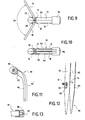
- the device is made in the form of a cane 9. It has a foot 90 which is located in its lower part and that is realized to be sunk into the ground. The foot 90 is beveled in the manner of a stake, to enter the ground more easily.
- the cane 9 also has, at the top, a handle 91 on which the hunter can support to push the foot 90 of the cane 9 in the ground.
- the rod 9 supports two flat mirrors reflectors 10 and 11. They are mounted symmetrically by compared to the plane of symmetry of the cane 9.
- the two mirrors 10 and 11 are pivotally mounted by their edge on the side wall of the cane 9 at its upper end, in the vicinity of its handle 91. To do this, the two mirrors 10 and 11 are mounted on hinges, respectively 12 and 13, represented in particular on Figures 7 and 8.
- the hinges 12 and 13 are of known type. They each constitute a hinge element that includes two parts enclosed in one another and joined by a common axis around which at least one of them can turn freely. One of these two pieces is fixed on the side wall of the rod 9, the other piece supports a mirror by its slice.
- the rod 9 comprises means for limit the orientation of the mirrors 10 and 11 in their positions extremes. As shown in Figures 9 and 10, each of mirrors 10 and 11 has a shim, respectively 20 and 21. Each of the holds is preferably attached to the back of each mirrors 10 and 11.
- the respective reflection axes of the two mirrors 10 and 11 are orientable in a horizontal plane, with respect to a plane of vertical symmetry defined by the support rod on which said mirrors are mounted (and that is the plane of symmetry of the cane), between two extreme positions defining between them an interval angular 50 (FIG. 9) corresponding to a safe firing zone on either side of a median line of sight located in plane of symmetry.
- the rod 9 comprises means for place the mirrors 10 and 11 in one or the other of two positions symmetrical remote a hunter user of the cane 9 in shooting position.
- the cane 9 has two symmetrical halves 92 and 93 made to be separated and gathered according to the plane of symmetry of the cane.
- Each of the two symmetrical halves 92 and 93 supports respectively one of the two mirrors 10 and 11 and they constitute together the means for placing the mirrors 10 and 11 in one or the other of two symmetrical positions at a distance from a hunter.
- the very realization of the cane in two halves each carrying a mirror allows to distance the two mirrors 10 and 11 of each other, and also to place the mirrors at distance from a hunter, for example in front of him, to his left and his right.
- the two halves 92 and 93 each have a flat wall, respectively 94 and 95, as seen on the Figures 11 and 7.
- the two walls planes 94 and 95 are contiguous according to the plane of symmetry of the cane 9 ( Figures 8, 9 and 10).
- the flat walls 94 and 95 constitute cue means for the hunter to place symmetrically the two halves of cane 92 and 93: it is enough for him to orient the two cane halves 92 and 93 such that the flat walls 94 and 95 are facing each other.
- the cane also comprises means the two halves of cane 92 and 93. These means are advantageously located at the ends of the rod 9, that is to say at the handle 91 ( Figures 11 and 13) and at the foot 90 ( Figure 12), for greater security of assembly of the two halves 92 and 93.
- Each of the halves 92 and 93 comprises, in part upper half of a handle 91.
- the two halves of handles are gathered in a hood 96 having a housing home of the two handle halves, the housing having a form complementary to that formed by the two halves of handle together according to the plane of symmetry.
- One of the two handle halves specifically that includes half cane 92 from Figures 7 and 11, has a protuberance 97.
- the protuberance 97 is shaped cylindrical and it is threaded.
- the cap 96 has a threaded cavity, of cylindrical shape whose dimensions are substantially equal to those of the protuberance 97 so that the protuberance 97 is screwed ( Figure 11). So, for combine the two halves of the handle, it is enough for the hunter to stick together against their flat surface and screw the cap over it by bringing the protuberance into the cavity.
- each of the halves of cane 92 and 93 comprises, in the lower part, a half foot 90.
- One of the halves of the foot, more precisely that which comprises half of rod 92 ( Figure 12) is traversed by a light 98.
- a collar 99 internally partially borders the inner rim of the light 98.
- the other half of the foot facing the light 98 presents a 14.
- a screw 15 for assembling the two is provided. foot halves, whose head is small enough to be introduced in the light 98 and big enough to abut the collar 99, the threaded body of the screw 15 having a diameter complementary to that of the threaded bore 14 to be screwed.
- the cane thus produced allows a user hunter to to choose more easily the limits of a safety zone in which he allows himself to shoot. It also allows the hunter user to anticipate the passage of an animal in this shooting zone safe.
- the cane is used in the following way: The hunter separates the two halves of cane 92 and 93 and he plants them each in the ground taking care that the flat walls 94 and 95 are arranged parallel to one another and perpendicular to the beaten line that the hunter forms with the neighboring hunters.
- the hunter then chooses two natural landmarks of his environment by looking in line with each of the flat mirrors to delimit the safety zone in which he allows himself to shoot.
- the hunter watches the safety zone holding his rifle in play and sweeping, from one landmark to another, the area with the barrel of his rifle.
- the hunter is warned of the next passage of an animal in the shooting zone that he allows himself when the image of an animal is reflected in either mirror 10 or 11. It thus anticipates the passage of this animal and he can determine if the animal comes from his right or his left. It is thus more likely to touch the animal.
Landscapes
- Engineering & Computer Science (AREA)
- General Engineering & Computer Science (AREA)
- Toys (AREA)
- Telephone Function (AREA)
- Adornments (AREA)
- Details Of Audible-Bandwidth Transducers (AREA)
- Medicines Containing Material From Animals Or Micro-Organisms (AREA)
- Mounting And Adjusting Of Optical Elements (AREA)
- Geophysics And Detection Of Objects (AREA)
- Optical Elements Other Than Lenses (AREA)
- Instruments For Viewing The Inside Of Hollow Bodies (AREA)
- Telescopes (AREA)
Applications Claiming Priority (2)
| Application Number | Priority Date | Filing Date | Title |
|---|---|---|---|
| FR0404253 | 2004-04-21 | ||
| FR0404253A FR2869200B1 (fr) | 2004-04-21 | 2004-04-21 | Appareil d'equipement accessoire pour chasseur |
Publications (3)
| Publication Number | Publication Date |
|---|---|
| EP1589313A2 true EP1589313A2 (de) | 2005-10-26 |
| EP1589313A3 EP1589313A3 (de) | 2006-05-17 |
| EP1589313B1 EP1589313B1 (de) | 2007-06-13 |
Family
ID=34942151
Family Applications (1)
| Application Number | Title | Priority Date | Filing Date |
|---|---|---|---|
| EP05290851A Expired - Lifetime EP1589313B1 (de) | 2004-04-21 | 2005-04-18 | Hilfsmittel für Jäger |
Country Status (4)
| Country | Link |
|---|---|
| EP (1) | EP1589313B1 (de) |
| AT (1) | ATE364828T1 (de) |
| DE (1) | DE602005001346D1 (de) |
| FR (1) | FR2869200B1 (de) |
Cited By (4)
| Publication number | Priority date | Publication date | Assignee | Title |
|---|---|---|---|---|
| FR2953924A1 (fr) * | 2009-12-14 | 2011-06-17 | Philippe Coste | Dispositif de marquage d'angles au sol |
| US20190162506A1 (en) * | 2017-11-29 | 2019-05-30 | Lonnie Dale Tustison | Firearm accessory holder |
| FR3078151A1 (fr) * | 2018-02-16 | 2019-08-23 | S30D | Dispositif de securite pour tireur |
| FR3084146A1 (fr) * | 2018-07-20 | 2020-01-24 | Edouard Jacques Michel Lemarie | Dispositif permettant de visualiser l'angle de securite de 30 degres requis pour le tir de chasse en battue |
Family Cites Families (7)
| Publication number | Priority date | Publication date | Assignee | Title |
|---|---|---|---|---|
| US370459A (en) * | 1887-09-27 | Sunshade-handle | ||
| US383598A (en) * | 1888-05-29 | Moeitz stiebeitz and adolph milleb | ||
| US1264133A (en) * | 1916-07-17 | 1918-04-23 | Ebenezer Reginald Morris | Rifle-periscope. |
| US4827652A (en) * | 1987-10-02 | 1989-05-09 | Martin Ernest J T | Cocking-bar, target-framing and range-finding, carrying, hanging and standing device |
| US6712058B2 (en) * | 2001-12-28 | 2004-03-30 | Porter Norman C | Camouflage and cover apparatus |
| US7007704B2 (en) * | 2002-01-02 | 2006-03-07 | Luckstead David G | Convertible walking aid |
| US7896508B2 (en) * | 2002-06-10 | 2011-03-01 | Dyson William E | Gun mirror |
-
2004
- 2004-04-21 FR FR0404253A patent/FR2869200B1/fr not_active Expired - Fee Related
-
2005
- 2005-04-18 EP EP05290851A patent/EP1589313B1/de not_active Expired - Lifetime
- 2005-04-18 DE DE602005001346T patent/DE602005001346D1/de not_active Expired - Lifetime
- 2005-04-18 AT AT05290851T patent/ATE364828T1/de not_active IP Right Cessation
Cited By (5)
| Publication number | Priority date | Publication date | Assignee | Title |
|---|---|---|---|---|
| FR2953924A1 (fr) * | 2009-12-14 | 2011-06-17 | Philippe Coste | Dispositif de marquage d'angles au sol |
| US20190162506A1 (en) * | 2017-11-29 | 2019-05-30 | Lonnie Dale Tustison | Firearm accessory holder |
| US11079201B2 (en) * | 2017-11-29 | 2021-08-03 | Lonnie Dale Tustison | Firearm accessory holder |
| FR3078151A1 (fr) * | 2018-02-16 | 2019-08-23 | S30D | Dispositif de securite pour tireur |
| FR3084146A1 (fr) * | 2018-07-20 | 2020-01-24 | Edouard Jacques Michel Lemarie | Dispositif permettant de visualiser l'angle de securite de 30 degres requis pour le tir de chasse en battue |
Also Published As
| Publication number | Publication date |
|---|---|
| EP1589313A3 (de) | 2006-05-17 |
| EP1589313B1 (de) | 2007-06-13 |
| FR2869200B1 (fr) | 2006-07-07 |
| FR2869200A1 (fr) | 2005-10-28 |
| DE602005001346D1 (de) | 2007-07-26 |
| ATE364828T1 (de) | 2007-07-15 |
Similar Documents
| Publication | Publication Date | Title |
|---|---|---|
| EP3870324A1 (de) | Spiele-controller mit mindestens einem schwenkbaren steuerelement mit veränderbarem anschlagwinkel | |
| BE1022467B1 (fr) | Labyrinthe cylindrique | |
| CH619370A5 (de) | ||
| EP0342109A2 (de) | Verschlusseinrichtung mit drehbarer Manschette für Flakons und ähnliche Behälter | |
| BE1026337A1 (fr) | Element de rotation et de reglage d’angle | |
| EP3870323A1 (de) | Spiele-controller mit mindestens einem abnehmbaren verstellelement zur anpassung des anschlagwinkels eines schwenkbaren steuerelements des controllers | |
| EP2048548A2 (de) | Hammer für ein Uhrwerk, damit ausgestattetes Uhrwerk, insbesondere Schlagwerk und mit diesen ausgestattete Uhr | |
| EP0342108A1 (de) | Versenkbare Pfeilauflage für einen Bogen | |
| EP1349451B1 (de) | Unterwasserharpune vom armbrusttyp mit spannvorrichtung | |
| EP1304538A1 (de) | Montageeinrichtung zum Aufsetzen einer Visiereinrichtung auf eine Feuerwaffe | |
| EP1589313B1 (de) | Hilfsmittel für Jäger | |
| EP0084813B1 (de) | Sicherheitsskibindung | |
| BE1016061A5 (fr) | Lance-grenades ameliore et fusil equipe d'un tel lance-grenades. | |
| FR2654358A1 (fr) | Fixation de securite a plaque. | |
| WO1997017569A1 (fr) | Ensemble de support d'une perche de prise de son | |
| WO1998018041A1 (fr) | Procede de liaison entre une branche et une façade de lunettes et charniere de lunettes | |
| EP1224958B1 (de) | Verbesserung für Schneeschuh und seine Bindung | |
| FR3004658A1 (fr) | Sac de golf | |
| EP4080154A1 (de) | Gewehrkolben mit verstellbarer positionierung | |
| BE502011A (de) | ||
| FR2760604A1 (fr) | Dispositif a crampons fixable pour chaussures de football | |
| FR2811419A1 (fr) | Arme pour le tir de precision | |
| WO2025074182A1 (fr) | Système multifonction pour paire de ski-roues | |
| EP4265997A1 (de) | Griff für einen mit einem griffkörper und einem griffkörper gebildeten griffbogen und bogen dafür | |
| FR3158242A1 (fr) | Jouet, de type toupie, comprenant des masselottes |
Legal Events
| Date | Code | Title | Description |
|---|---|---|---|
| PUAI | Public reference made under article 153(3) epc to a published international application that has entered the european phase |
Free format text: ORIGINAL CODE: 0009012 |
|
| AK | Designated contracting states |
Kind code of ref document: A2 Designated state(s): AT BE BG CH CY CZ DE DK EE ES FI FR GB GR HU IE IS IT LI LT LU MC NL PL PT RO SE SI SK TR |
|
| AX | Request for extension of the european patent |
Extension state: AL BA HR LV MK YU |
|
| PUAL | Search report despatched |
Free format text: ORIGINAL CODE: 0009013 |
|
| AK | Designated contracting states |
Kind code of ref document: A3 Designated state(s): AT BE BG CH CY CZ DE DK EE ES FI FR GB GR HU IE IS IT LI LT LU MC NL PL PT RO SE SI SK TR |
|
| AX | Request for extension of the european patent |
Extension state: AL BA HR LV MK YU |
|
| 17P | Request for examination filed |
Effective date: 20060926 |
|
| GRAP | Despatch of communication of intention to grant a patent |
Free format text: ORIGINAL CODE: EPIDOSNIGR1 |
|
| AKX | Designation fees paid |
Designated state(s): AT BE BG CH CY CZ DE DK EE ES FI FR GB GR HU IE IS IT LI LT LU MC NL PL PT RO SE SI SK TR |
|
| GRAS | Grant fee paid |
Free format text: ORIGINAL CODE: EPIDOSNIGR3 |
|
| GRAA | (expected) grant |
Free format text: ORIGINAL CODE: 0009210 |
|
| AK | Designated contracting states |
Kind code of ref document: B1 Designated state(s): AT BE BG CH CY CZ DE DK EE ES FI FR GB GR HU IE IS IT LI LT LU MC NL PL PT RO SE SI SK TR |
|
| REG | Reference to a national code |
Ref country code: GB Ref legal event code: FG4D Free format text: NOT ENGLISH |
|
| REG | Reference to a national code |
Ref country code: CH Ref legal event code: EP |
|
| REG | Reference to a national code |
Ref country code: IE Ref legal event code: FG4D Free format text: LANGUAGE OF EP DOCUMENT: FRENCH |
|
| REF | Corresponds to: |
Ref document number: 602005001346 Country of ref document: DE Date of ref document: 20070726 Kind code of ref document: P |
|
| PG25 | Lapsed in a contracting state [announced via postgrant information from national office to epo] |
Ref country code: SE Free format text: LAPSE BECAUSE OF FAILURE TO SUBMIT A TRANSLATION OF THE DESCRIPTION OR TO PAY THE FEE WITHIN THE PRESCRIBED TIME-LIMIT Effective date: 20070913 |
|
| PG25 | Lapsed in a contracting state [announced via postgrant information from national office to epo] |
Ref country code: AT Free format text: LAPSE BECAUSE OF FAILURE TO SUBMIT A TRANSLATION OF THE DESCRIPTION OR TO PAY THE FEE WITHIN THE PRESCRIBED TIME-LIMIT Effective date: 20070613 Ref country code: PL Free format text: LAPSE BECAUSE OF FAILURE TO SUBMIT A TRANSLATION OF THE DESCRIPTION OR TO PAY THE FEE WITHIN THE PRESCRIBED TIME-LIMIT Effective date: 20070613 |
|
| NLV1 | Nl: lapsed or annulled due to failure to fulfill the requirements of art. 29p and 29m of the patents act | ||
| GBV | Gb: ep patent (uk) treated as always having been void in accordance with gb section 77(7)/1977 [no translation filed] |
Effective date: 20070613 |
|
| REG | Reference to a national code |
Ref country code: IE Ref legal event code: FD4D |
|
| PG25 | Lapsed in a contracting state [announced via postgrant information from national office to epo] |
Ref country code: SI Free format text: LAPSE BECAUSE OF FAILURE TO SUBMIT A TRANSLATION OF THE DESCRIPTION OR TO PAY THE FEE WITHIN THE PRESCRIBED TIME-LIMIT Effective date: 20070613 Ref country code: PT Free format text: LAPSE BECAUSE OF FAILURE TO SUBMIT A TRANSLATION OF THE DESCRIPTION OR TO PAY THE FEE WITHIN THE PRESCRIBED TIME-LIMIT Effective date: 20071113 Ref country code: ES Free format text: LAPSE BECAUSE OF FAILURE TO SUBMIT A TRANSLATION OF THE DESCRIPTION OR TO PAY THE FEE WITHIN THE PRESCRIBED TIME-LIMIT Effective date: 20070924 Ref country code: CZ Free format text: LAPSE BECAUSE OF FAILURE TO SUBMIT A TRANSLATION OF THE DESCRIPTION OR TO PAY THE FEE WITHIN THE PRESCRIBED TIME-LIMIT Effective date: 20070613 Ref country code: BG Free format text: LAPSE BECAUSE OF FAILURE TO SUBMIT A TRANSLATION OF THE DESCRIPTION OR TO PAY THE FEE WITHIN THE PRESCRIBED TIME-LIMIT Effective date: 20070913 Ref country code: IS Free format text: LAPSE BECAUSE OF FAILURE TO SUBMIT A TRANSLATION OF THE DESCRIPTION OR TO PAY THE FEE WITHIN THE PRESCRIBED TIME-LIMIT Effective date: 20071013 Ref country code: NL Free format text: LAPSE BECAUSE OF FAILURE TO SUBMIT A TRANSLATION OF THE DESCRIPTION OR TO PAY THE FEE WITHIN THE PRESCRIBED TIME-LIMIT Effective date: 20070613 Ref country code: IE Free format text: LAPSE BECAUSE OF FAILURE TO SUBMIT A TRANSLATION OF THE DESCRIPTION OR TO PAY THE FEE WITHIN THE PRESCRIBED TIME-LIMIT Effective date: 20070613 |
|
| PG25 | Lapsed in a contracting state [announced via postgrant information from national office to epo] |
Ref country code: LT Free format text: LAPSE BECAUSE OF FAILURE TO SUBMIT A TRANSLATION OF THE DESCRIPTION OR TO PAY THE FEE WITHIN THE PRESCRIBED TIME-LIMIT Effective date: 20070613 Ref country code: SK Free format text: LAPSE BECAUSE OF FAILURE TO SUBMIT A TRANSLATION OF THE DESCRIPTION OR TO PAY THE FEE WITHIN THE PRESCRIBED TIME-LIMIT Effective date: 20070613 |
|
| PLBE | No opposition filed within time limit |
Free format text: ORIGINAL CODE: 0009261 |
|
| STAA | Information on the status of an ep patent application or granted ep patent |
Free format text: STATUS: NO OPPOSITION FILED WITHIN TIME LIMIT |
|
| PG25 | Lapsed in a contracting state [announced via postgrant information from national office to epo] |
Ref country code: DE Free format text: LAPSE BECAUSE OF FAILURE TO SUBMIT A TRANSLATION OF THE DESCRIPTION OR TO PAY THE FEE WITHIN THE PRESCRIBED TIME-LIMIT Effective date: 20070914 Ref country code: IT Free format text: LAPSE BECAUSE OF FAILURE TO SUBMIT A TRANSLATION OF THE DESCRIPTION OR TO PAY THE FEE WITHIN THE PRESCRIBED TIME-LIMIT Effective date: 20070613 Ref country code: GR Free format text: LAPSE BECAUSE OF FAILURE TO SUBMIT A TRANSLATION OF THE DESCRIPTION OR TO PAY THE FEE WITHIN THE PRESCRIBED TIME-LIMIT Effective date: 20070914 Ref country code: DK Free format text: LAPSE BECAUSE OF FAILURE TO SUBMIT A TRANSLATION OF THE DESCRIPTION OR TO PAY THE FEE WITHIN THE PRESCRIBED TIME-LIMIT Effective date: 20070613 Ref country code: GB Free format text: LAPSE BECAUSE OF FAILURE TO SUBMIT A TRANSLATION OF THE DESCRIPTION OR TO PAY THE FEE WITHIN THE PRESCRIBED TIME-LIMIT Effective date: 20070613 |
|
| 26N | No opposition filed |
Effective date: 20080314 |
|
| PG25 | Lapsed in a contracting state [announced via postgrant information from national office to epo] |
Ref country code: RO Free format text: LAPSE BECAUSE OF FAILURE TO SUBMIT A TRANSLATION OF THE DESCRIPTION OR TO PAY THE FEE WITHIN THE PRESCRIBED TIME-LIMIT Effective date: 20070613 |
|
| BERE | Be: lapsed |
Owner name: ARMURERIE BILLAULT Effective date: 20080430 |
|
| PG25 | Lapsed in a contracting state [announced via postgrant information from national office to epo] |
Ref country code: MC Free format text: LAPSE BECAUSE OF NON-PAYMENT OF DUE FEES Effective date: 20080430 |
|
| PG25 | Lapsed in a contracting state [announced via postgrant information from national office to epo] |
Ref country code: EE Free format text: LAPSE BECAUSE OF FAILURE TO SUBMIT A TRANSLATION OF THE DESCRIPTION OR TO PAY THE FEE WITHIN THE PRESCRIBED TIME-LIMIT Effective date: 20070613 |
|
| PG25 | Lapsed in a contracting state [announced via postgrant information from national office to epo] |
Ref country code: FI Free format text: LAPSE BECAUSE OF FAILURE TO SUBMIT A TRANSLATION OF THE DESCRIPTION OR TO PAY THE FEE WITHIN THE PRESCRIBED TIME-LIMIT Effective date: 20070613 |
|
| PG25 | Lapsed in a contracting state [announced via postgrant information from national office to epo] |
Ref country code: BE Free format text: LAPSE BECAUSE OF NON-PAYMENT OF DUE FEES Effective date: 20080430 |
|
| PG25 | Lapsed in a contracting state [announced via postgrant information from national office to epo] |
Ref country code: CY Free format text: LAPSE BECAUSE OF FAILURE TO SUBMIT A TRANSLATION OF THE DESCRIPTION OR TO PAY THE FEE WITHIN THE PRESCRIBED TIME-LIMIT Effective date: 20070613 |
|
| REG | Reference to a national code |
Ref country code: CH Ref legal event code: PL |
|
| PG25 | Lapsed in a contracting state [announced via postgrant information from national office to epo] |
Ref country code: CH Free format text: LAPSE BECAUSE OF NON-PAYMENT OF DUE FEES Effective date: 20090430 Ref country code: LI Free format text: LAPSE BECAUSE OF NON-PAYMENT OF DUE FEES Effective date: 20090430 |
|
| PG25 | Lapsed in a contracting state [announced via postgrant information from national office to epo] |
Ref country code: LU Free format text: LAPSE BECAUSE OF NON-PAYMENT OF DUE FEES Effective date: 20080418 Ref country code: HU Free format text: LAPSE BECAUSE OF FAILURE TO SUBMIT A TRANSLATION OF THE DESCRIPTION OR TO PAY THE FEE WITHIN THE PRESCRIBED TIME-LIMIT Effective date: 20071214 |
|
| PG25 | Lapsed in a contracting state [announced via postgrant information from national office to epo] |
Ref country code: TR Free format text: LAPSE BECAUSE OF FAILURE TO SUBMIT A TRANSLATION OF THE DESCRIPTION OR TO PAY THE FEE WITHIN THE PRESCRIBED TIME-LIMIT Effective date: 20070613 |
|
| REG | Reference to a national code |
Ref country code: FR Ref legal event code: PLFP Year of fee payment: 12 |
|
| PGFP | Annual fee paid to national office [announced via postgrant information from national office to epo] |
Ref country code: FR Payment date: 20160330 Year of fee payment: 12 |
|
| REG | Reference to a national code |
Ref country code: FR Ref legal event code: ST Effective date: 20171229 |
|
| PG25 | Lapsed in a contracting state [announced via postgrant information from national office to epo] |
Ref country code: FR Free format text: LAPSE BECAUSE OF NON-PAYMENT OF DUE FEES Effective date: 20170502 |