EP1589313A2 - Accessory for hunters - Google Patents
Accessory for hunters Download PDFInfo
- Publication number
- EP1589313A2 EP1589313A2 EP05290851A EP05290851A EP1589313A2 EP 1589313 A2 EP1589313 A2 EP 1589313A2 EP 05290851 A EP05290851 A EP 05290851A EP 05290851 A EP05290851 A EP 05290851A EP 1589313 A2 EP1589313 A2 EP 1589313A2
- Authority
- EP
- European Patent Office
- Prior art keywords
- mirror
- arm
- plane
- symmetry
- hunter
- Prior art date
- Legal status (The legal status is an assumption and is not a legal conclusion. Google has not performed a legal analysis and makes no representation as to the accuracy of the status listed.)
- Granted
Links
Images
Classifications
-
- F—MECHANICAL ENGINEERING; LIGHTING; HEATING; WEAPONS; BLASTING
- F41—WEAPONS
- F41A—FUNCTIONAL FEATURES OR DETAILS COMMON TO BOTH SMALLARMS AND ORDNANCE, e.g. CANNONS; MOUNTINGS FOR SMALLARMS OR ORDNANCE
- F41A21/00—Barrels; Gun tubes; Muzzle attachments; Barrel mounting means
- F41A21/32—Muzzle attachments or glands
- F41A21/325—Mountings for muzzle attachments
-
- F—MECHANICAL ENGINEERING; LIGHTING; HEATING; WEAPONS; BLASTING
- F41—WEAPONS
- F41A—FUNCTIONAL FEATURES OR DETAILS COMMON TO BOTH SMALLARMS AND ORDNANCE, e.g. CANNONS; MOUNTINGS FOR SMALLARMS OR ORDNANCE
- F41A35/00—Accessories or details not otherwise provided for
-
- F—MECHANICAL ENGINEERING; LIGHTING; HEATING; WEAPONS; BLASTING
- F41—WEAPONS
- F41C—SMALLARMS, e.g. PISTOLS, RIFLES; ACCESSORIES THEREFOR
- F41C27/00—Accessories; Details or attachments not otherwise provided for
Definitions
- the present invention relates to the design and realization of a device of accessory equipment for hunter. It aims to improve the safety conditions of hunting in collective practice while facilitating the aim of the hunter.
- Hunting usually consists of watching and chasing animals to kill them as part of a hobby, or out of necessity.
- the hunters are led to place themselves along an imaginary line, called the line of battue, while keeping between them distances which are supposed to limit the risk that an animal could pass between two hunters.
- hunters must be careful not to hurt each other.
- hunters limit their fire in an area called a safety zone between two lines of sight that the hunters impose on both sides of a plane perpendicular to the line of battue.
- An accessory equipment apparatus for fighter designed to improve the safety conditions of the hunting in collective practice, including making it easier to each hunter to set limits beyond which a shot targeted towards a passing animal in his shooting range could be dangerous by making him run the risk of hurting a hunter neighbour.
- the apparatus comprises at least one mirror reflective whose axis of reflection is orientable in a plane horizontally, with respect to a vertical plane of symmetry defined by a support on which it is mounted, between two extreme positions defining between them an angular interval corresponding to a safe shooting zone on either side of a line of sight median located in said plane of symmetry.
- the apparatus according to the invention allows a hunter to choose more easily landmarks to limit his area safe shooting.
- hunters take natural landmarks from those around them, such as trees. or bushes. Ideally, hunters choose these markers in two symmetrically inclined directions of about thirty degrees from the beat line.
- the safety zone in which the hunters limit their aim has an angle of opening that is complementary to those in which the hunters do not allow themselves to shoot.
- the apparatus according to the invention allows the hunter to choose your natural landmarks by looking in the extension of the mirror placed in one or other of the two extreme positions.
- the apparatus according to the invention allows a hunter to anticipate the passage of an animal before the animal enters the safe area the hunter has defined himself, without however, lose his line of sight, thanks to the presence of the mirror. Of therefore, the chances of touching an animal are increased.
- the apparatus comprises means for place the mirror in one or the other of two symmetrical positions remote from a user hunter of said apparatus in firing position.
- the device is easier to use for the hunter and the mirror placed at a distance gives him a broader vision what is going on beyond his safe shooting range.
- the latter is designed to be fixed on the gun of a rifle.
- the apparatus according to the invention comprises advantageously a support plate which has means of fixing on the barrel of a rifle and on which an arm is mounted pivoting between said two symmetrical positions, said mirror being mounted at one end of said arm.
- the plane of symmetry is vertical and passes through the barrel axis of the rifle on which the platinum bracket is attached, and the arm is a way to place the mirror remote from a user hunter of said apparatus in firing position.
- the means allowing to place the mirror in one or the other of two positions symmetrical consist of two partial housing imprints of the arms that are arranged symmetrically with respect to the plane of symmetry in said platen, providing a temporary lock of the orientation of the arm, and therefore of the mirror, according to the two positions extremes.
- the device allows the hunter to choose more conveniently the natural landmarks following the limiting directions between which the hunter will allow himself to shoot: It is enough for him to use the apparatus according to the invention by placing the barrel of its rifle right in front of him (perpendicular to the beat line), then looking in the extension of the arm supporting the mirror, placed in either of the two footprints, to find both natural elements of its environment to consider to limit his range of fire.
- Each of the cavities is advantageously arranged in the plate in such a way that the arm is oriented angle of sixty degrees from the plane of symmetry.
- the device responds to the most common choice of hunters, this choice being to consider a safe shooting angle of sixty degrees of both sides of the barrel of their rifle when they direct it right in front of them.
- a third impression is advantageously provided in the plate following the plane of symmetry, so as to position the arm and temporarily lock the position of the arm in the extension of the axis of the barrel of the rifle. This allows you to tidy up the device in a space smaller than that which would have to be provided if the device did not allow to fold the arm in one direction parallel to that of the barrel.
- the arm comprises two tubes mounted telescopically sliding one into the other and a ring of temporary fixing of these tubes relative to each other.
- the hunter thus has the opportunity to reduce the length of the arm.
- This realization allows then to store the device in a space more small if the arm was not telescopic.
- the telescopic arm, in the folded position has a length less than the length of the barrel.
- the mirror is rotatably mounted around the axis of the arm, so that the hunter can modify the orientation of the reflection axis of the mirror in a vertical plane.
- a hunting accessory according to the invention, it is made to be fixed temporarily in the soil.
- the apparatus according to the invention advantageously comprises this effect a cane support two mirrors that are mounted pivoting by their edge on the side wall of said rod to one of its ends.
- the plane of symmetry considered is that of the cane following its length, passing in the middle.
- the apparatus comprises two shims, each of the shims being preferentially attached to the back of each mirrors.
- the wedges limit the orientation of the mirrors in two extreme positions defining between them an angular interval corresponding to a zone fired safely on both sides of a median line of sight located in said plane of symmetry.
- the cane has two halves symmetrical made to be separated and collected according to the plane of symmetry, each of the two halves presenting one of the two mirrors.
- the two symmetrical halves of cane constitute the means for placing the mirrors in one or the other of two symmetrical positions at a distance from the hunter.
- the hunter can use this accessory thus produced according to the invention to determine its firing range: It separates the two halves symmetrical trunk, by pressing the foot of each half trunk to his right and to his left taking care of good arrange the two halves symmetrically with respect to the plane of symmetry, perpendicular to the beat line. Then he rotates the two mirrors until their wedge comes up against the wall lateral of each of the trunk halves. It can easily choose the boundaries of your firing zone by taking two points elements of his environment each located in the extension of the plans of the mirrors.
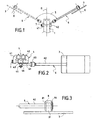
- the apparatus according to the invention is designed to be attached to the barrel 1 of a shotgun 2, such as that which is illustrated in Figure 6.
- the butt of the rifle 2 is represented decorated incidentally a dog's head, which may correspond to the head the hunter's dog user of this rifle. It must be understood that the butt of the rifle could be decorated with another head of dog, or not be decorated at all.
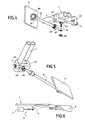
- the apparatus according to the invention is attached to the barrel of a rifle by means of a plate 4 that the device comprises ( Figure 2).
- the plate 4 has two jaws 41 and 42 whose tightening secures the device to the barrel 1. Both jaws are shown clearly in Figures 2, 4 and 5.
- the jaw 42 is fixed and the jaw 41 is movable.
- Platinum 4 has a screw 7 which allows to bring the jaw 41 of the jaw 42 and thus strongly seize the barrel 1 of the rifle between two jaws 41 and 42, as shown in FIG. head of the screw is knurled to be turned by hand more easily and his body is screwed into a tapped channel in the turntable 4, shown in FIG.
- the apparatus has at least one reflecting plane mirror 3 whose axis of reflection X is orientable in a horizontal plane, with respect to a plane of vertical symmetry defined by the plate 4, supporting an arm 6 at the end of which is mounted the mirror 3.
- the plate 4 thus supports indirectly the mirror 3.
- the freedom of orientation of the axis of mirror reflection 3 extends between two extreme positions symmetrical.
- FIG. 1 shows the two extreme positions of the mirror X axis of reflection.
- the two extreme positions of the X axis correspond respectively to two extreme positions of the mirror.
- One of the extreme positions of the mirror 3 is represented in solid lines and the other extreme position of the mirror 3 is shown in dotted lines.
- the two extreme positions of the plane of the mirror define between them an angular interval 5, represented in FIG. 1, corresponding to a safe shooting zone on either side a median line of sight D which is located in said plane of symmetry.
- the arm 6 is pivoted by one of its ends on the plate 4 between the two extreme positions shown in Figure 1, the mirror 3 being mounted at the other end of the arm 6.
- the arm 6 constitutes a means for placing the mirror 3 to distance from a hunter.
- it comprises two tubes 61 and 62 mounted telescopically sliding one into the other and a ring 63 temporarily fixing the position of these tubes relative to each other to the other.
- the hunter can vary the length of the arm 6 to move more or less away the mirror 3.
- This telescopic arm construction offers the advantage of ability to store the device in a smaller space than the one it would be necessary if the arm was not telescopic.
- the folded telescopic arm has a length which is less than that of the barrel, so that the whole consisting of the rifle and the device occupies a storage length identical to that originally planned for the rifle alone.
- two impressions 43 and 44 are arranged symmetrically with respect to the plane of symmetry in the support plate 4 (FIGS. 4 and 5).
- the two prints 43 and 44 are realized in such a way that the arm 6 is partially lodged therein.
- a knurled knob 45 screwed onto a threaded rod 16 crossing the end arm and plate ( Figure 4), allows, like a nut, to hold the arm in position in one or the other of the impressions 43 or 44.
- Each of the fingerprints 43 and 44 is provided in the platen 4 so that the arm 6 can be oriented advantageously at an angle of sixty degrees to the line of sight D, on both sides of the barrel 1 of the rifle 2.
- a third impression 46 is formed in the plate 4 following said plane of symmetry ( Figure 5). This third impression allows to place the arm 6 in the same plane as that of the rifle, by example to store it, as shown in Figure 6.
- FIG. 3 represents the mounting means of the mirror 3 to the end of the arm 6.
- the mirror 3 is mounted free to rotate about the axis of the 6.
- a tip 8 comprising a ring forming a shoulder 81, is attached to the end of the arm 6 so that the shoulder 81 is set back relative to the end of the arm 6.
- the maintaining the tip 8 on the arm 6 is done by insertion and fixation, by any known means, the end of the arm 6 (end of the tube 62 in FIG. 3) in a housing formed in the end piece 8 its axis.
- the mirror 3 has, on the opposite side to the one that is reflective and in the axis of reflection X, a ring integral 31 (also shown in Figure 4) whose diameter internal is equal to the game close to that of the tip 8 to be able to be slidably mounted around the latter at the end of the arm 6.
- the inner diameter of ring 31 is also slightly lower to that of the ring forming the shoulder 81 so that the ring 31 take support against him.
- the ring forming the shoulder 81 thus constitutes a stop for the ring 31 integral with the mirror 3.
- the ring 31 and the mirror 3 can rotate freely around the axis of the arm 6.
- a ring 64 of truncated conical section elastically deformable is fixed around the piece 8, against the ring 31 which is integral with the mirror, opposite the shoulder 81.
- the mirror 3 remains in the position that the hunter gave him if he does not exercise the necessary strength to make it turn.
- the hunter can, however, orient the mirror to its suitability by rotating it around the axis of the arm 6 if it longed for.
- the apparatus according to the invention facilitates hunting conditions. For that, it must be used in the way next:
- the hunter fixes the device on the barrel 1 of his rifle 2 by tightening the screw 7 so that the jaws 41 and 42 trap strongly the barrel of the weapon.
- the fixed hunter the device in the middle of the barrel length so as to unbalance the rifle as little as possible and to have visibility bigger than he would have if he fixed the camera on the barrel at closer to the stick.
- the hunter places himself in the line of neighboring hunters, following the imaginary beat line, for take two landmarks, among those who offer themselves around him, for limit an area in which he will allow himself to shoot.
- the fighter clears the arm 6 of the footprint 46. He then places the arm 6 in the first footprint 44 and tightens the button 45 to maintain the arm 6 in position in the footprint 44. He then looks into the extension arm 6 and mirror 3 to distinguish a first natural element that he chooses as a first limit beyond which he does not will not allow himself to shoot.
- the hunter loosens the button 45 to release the arm 6 of the impression 44. He places the arm 6 in the second footprint 43 and holding in it by turning the knob 45. It then chooses a second landmark by looking in the extension arm 6 and mirror 3 thus positioned.
- the hunter monitors this area by keeping his rifle in play, looking into the continuation of the rifle barrel.
- the hunter sees it and anticipates the passage of the animal in its safe shooting zone. It can thus more easily touch him.
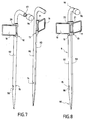
- the apparatus according to the invention is made to be fixed temporarily in the ground, to distance from a hunter user of the device.
- the device is made in the form of a cane 9. It has a foot 90 which is located in its lower part and that is realized to be sunk into the ground. The foot 90 is beveled in the manner of a stake, to enter the ground more easily.
- the cane 9 also has, at the top, a handle 91 on which the hunter can support to push the foot 90 of the cane 9 in the ground.
- the rod 9 supports two flat mirrors reflectors 10 and 11. They are mounted symmetrically by compared to the plane of symmetry of the cane 9.
- the two mirrors 10 and 11 are pivotally mounted by their edge on the side wall of the cane 9 at its upper end, in the vicinity of its handle 91. To do this, the two mirrors 10 and 11 are mounted on hinges, respectively 12 and 13, represented in particular on Figures 7 and 8.
- the hinges 12 and 13 are of known type. They each constitute a hinge element that includes two parts enclosed in one another and joined by a common axis around which at least one of them can turn freely. One of these two pieces is fixed on the side wall of the rod 9, the other piece supports a mirror by its slice.
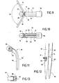
- the rod 9 comprises means for limit the orientation of the mirrors 10 and 11 in their positions extremes. As shown in Figures 9 and 10, each of mirrors 10 and 11 has a shim, respectively 20 and 21. Each of the holds is preferably attached to the back of each mirrors 10 and 11.
- the respective reflection axes of the two mirrors 10 and 11 are orientable in a horizontal plane, with respect to a plane of vertical symmetry defined by the support rod on which said mirrors are mounted (and that is the plane of symmetry of the cane), between two extreme positions defining between them an interval angular 50 (FIG. 9) corresponding to a safe firing zone on either side of a median line of sight located in plane of symmetry.
- the rod 9 comprises means for place the mirrors 10 and 11 in one or the other of two positions symmetrical remote a hunter user of the cane 9 in shooting position.
- the cane 9 has two symmetrical halves 92 and 93 made to be separated and gathered according to the plane of symmetry of the cane.
- Each of the two symmetrical halves 92 and 93 supports respectively one of the two mirrors 10 and 11 and they constitute together the means for placing the mirrors 10 and 11 in one or the other of two symmetrical positions at a distance from a hunter.
- the very realization of the cane in two halves each carrying a mirror allows to distance the two mirrors 10 and 11 of each other, and also to place the mirrors at distance from a hunter, for example in front of him, to his left and his right.
- the two halves 92 and 93 each have a flat wall, respectively 94 and 95, as seen on the Figures 11 and 7.
- the two walls planes 94 and 95 are contiguous according to the plane of symmetry of the cane 9 ( Figures 8, 9 and 10).
- the flat walls 94 and 95 constitute cue means for the hunter to place symmetrically the two halves of cane 92 and 93: it is enough for him to orient the two cane halves 92 and 93 such that the flat walls 94 and 95 are facing each other.
- the cane also comprises means the two halves of cane 92 and 93. These means are advantageously located at the ends of the rod 9, that is to say at the handle 91 ( Figures 11 and 13) and at the foot 90 ( Figure 12), for greater security of assembly of the two halves 92 and 93.
- Each of the halves 92 and 93 comprises, in part upper half of a handle 91.
- the two halves of handles are gathered in a hood 96 having a housing home of the two handle halves, the housing having a form complementary to that formed by the two halves of handle together according to the plane of symmetry.
- One of the two handle halves specifically that includes half cane 92 from Figures 7 and 11, has a protuberance 97.
- the protuberance 97 is shaped cylindrical and it is threaded.
- the cap 96 has a threaded cavity, of cylindrical shape whose dimensions are substantially equal to those of the protuberance 97 so that the protuberance 97 is screwed ( Figure 11). So, for combine the two halves of the handle, it is enough for the hunter to stick together against their flat surface and screw the cap over it by bringing the protuberance into the cavity.
- each of the halves of cane 92 and 93 comprises, in the lower part, a half foot 90.
- One of the halves of the foot, more precisely that which comprises half of rod 92 ( Figure 12) is traversed by a light 98.
- a collar 99 internally partially borders the inner rim of the light 98.
- the other half of the foot facing the light 98 presents a 14.
- a screw 15 for assembling the two is provided. foot halves, whose head is small enough to be introduced in the light 98 and big enough to abut the collar 99, the threaded body of the screw 15 having a diameter complementary to that of the threaded bore 14 to be screwed.
- the cane thus produced allows a user hunter to to choose more easily the limits of a safety zone in which he allows himself to shoot. It also allows the hunter user to anticipate the passage of an animal in this shooting zone safe.
- the cane is used in the following way: The hunter separates the two halves of cane 92 and 93 and he plants them each in the ground taking care that the flat walls 94 and 95 are arranged parallel to one another and perpendicular to the beaten line that the hunter forms with the neighboring hunters.
- the hunter then chooses two natural landmarks of his environment by looking in line with each of the flat mirrors to delimit the safety zone in which he allows himself to shoot.
- the hunter watches the safety zone holding his rifle in play and sweeping, from one landmark to another, the area with the barrel of his rifle.
- the hunter is warned of the next passage of an animal in the shooting zone that he allows himself when the image of an animal is reflected in either mirror 10 or 11. It thus anticipates the passage of this animal and he can determine if the animal comes from his right or his left. It is thus more likely to touch the animal.
Landscapes
- Engineering & Computer Science (AREA)
- General Engineering & Computer Science (AREA)
- Toys (AREA)
- Medicines Containing Material From Animals Or Micro-Organisms (AREA)
- Telephone Function (AREA)
- Adornments (AREA)
- Details Of Audible-Bandwidth Transducers (AREA)
- Mounting And Adjusting Of Optical Elements (AREA)
- Geophysics And Detection Of Objects (AREA)
- Optical Elements Other Than Lenses (AREA)
- Instruments For Viewing The Inside Of Hollow Bodies (AREA)
- Telescopes (AREA)
Abstract
Description
La présente invention concerne la conception et la réalisation d'un appareil d'équipement accessoire pour chasseur. Elle vise à améliorer les conditions de sécurité de la chasse en pratique collective tout en facilitant la visée du chasseur.The present invention relates to the design and realization of a device of accessory equipment for hunter. It aims to improve the safety conditions of hunting in collective practice while facilitating the aim of the hunter.
La chasse consiste généralement à guetter et à poursuivre
des animaux pour les tuer dans le cadre d'un loisir, ou par
nécessité. Lors des battues,
où la chasse est pratiquée en collectivité, les chasseurs
sont amenés à se placer le long d'une ligne imaginaire, appelée
ligne de battue, en conservant entre eux des distances qui sont
supposées limiter le risque qu'un animal puisse passer entre deux
chasseurs. Parallèlement, les chasseurs doivent s'assurer de ne pas
se blesser entre eux. Aussi, les chasseurs limitent leurs tirs dans
une zone appelée zone de sécurité située entre deux directions de
visée limites que les chasseurs s'imposent de part et d'autre d'un
plan perpendiculaire à la ligne de battue.Hunting usually consists of watching and chasing animals to kill them as part of a hobby, or out of necessity. When beaten,
where hunting is practiced in the community, the hunters are led to place themselves along an imaginary line, called the line of battue, while keeping between them distances which are supposed to limit the risk that an animal could pass between two hunters. At the same time, hunters must be careful not to hurt each other. Also, hunters limit their fire in an area called a safety zone between two lines of sight that the hunters impose on both sides of a plane perpendicular to the line of battue.
L'invention concerne un appareil d'équipement accessoire pour chasseur conçu pour améliorer les conditions de sécurité de la chasse en pratique collective, notamment en rendant plus facile à chaque chasseur de se fixer des limites au-delà desquelles un tir ciblé vers un animal de passage dans son champ de tir pourrait être dangereux en lui faisant courir le risque de blesser un chasseur voisin.An accessory equipment apparatus for fighter designed to improve the safety conditions of the hunting in collective practice, including making it easier to each hunter to set limits beyond which a shot targeted towards a passing animal in his shooting range could be dangerous by making him run the risk of hurting a hunter neighbour.
L'appareil selon l'invention comporte au moins un miroir réfléchissant dont l'axe de réflexion est orientable dans un plan horizontal, par rapport à un plan de symétrie vertical défini par un support sur lequel il est monté, entre deux positions extrêmes définissant entre elles un intervalle angulaire correspondant à une zone de tir en sécurité de part et d'autre d'une ligne de visée médiane située dans ledit plan de symétrie.The apparatus according to the invention comprises at least one mirror reflective whose axis of reflection is orientable in a plane horizontally, with respect to a vertical plane of symmetry defined by a support on which it is mounted, between two extreme positions defining between them an angular interval corresponding to a safe shooting zone on either side of a line of sight median located in said plane of symmetry.
Ainsi conçu, l'appareil selon l'invention permet à un chasseur de choisir plus facilement des repères pour limiter sa zone de tir en sécurité. Thus designed, the apparatus according to the invention allows a hunter to choose more easily landmarks to limit his area safe shooting.
En effet, de manière courante, pour définir la zone dans
laquelle ils s'autorisent à tirer, les chasseurs prennent des repères
naturels parmi ceux qui s'offrent autour d'eux, tels que des arbres
ou des buissons. Idéalement, les chasseurs choisissent ces repères
suivant deux directions inclinées symétriquement d'environ trente
degrés de la ligne de battue. La zone de sécurité dans laquelle les
chasseurs limitent leur visée présente un angle d'ouverture qui est
complémentaire à celles dans lesquelles les chasseurs ne
s'autorisent pas à tirer.Indeed, in order to define the area in which they allow themselves to shoot, hunters take natural landmarks from those around them, such as trees.
or bushes. Ideally, hunters choose these markers in two symmetrically inclined directions of about thirty degrees from the beat line. The safety zone in which the hunters limit their aim has an angle of opening that is complementary to those in which the hunters do not allow themselves to shoot.
Ainsi conçu, l'appareil selon l'invention permet au chasseur de choisir ses repères naturels en regardant dans le prolongement du miroir placé dans l'une ou l'autre des deux positions extrêmes.Thus designed, the apparatus according to the invention allows the hunter to choose your natural landmarks by looking in the extension of the mirror placed in one or other of the two extreme positions.
Parallèlement, l'appareil selon l'invention permet à un chasseur d'anticiper le passage d'un animal avant que l'animal ne pénètre dans la zone de sécurité que le chasseur s'est définie, sans toutefois perdre sa ligne de visée, grâce à la présence du miroir. De ce fait, les chances de toucher un animal sont augmentées.In parallel, the apparatus according to the invention allows a hunter to anticipate the passage of an animal before the animal enters the safe area the hunter has defined himself, without however, lose his line of sight, thanks to the presence of the mirror. Of therefore, the chances of touching an animal are increased.
En effet, les tirs des chasseurs sont opérés sur des animaux en mouvement. Aussi, les chasseurs ne tirent pas sur les animaux qu'ils visent mais ils tirent en avant, de façon à ce que les animaux coupent la trajectoire des plombs des cartouches. Le fait de pouvoir anticiper le passage d'un animal augmente alors les chances de le toucher.Indeed, the firing of the hunters are operated on moving animals. Also, hunters do not shoot at they are aiming at but they are pulling forward, so that animals cut the trajectory of the lead shots of the cartridges. The fact of can anticipate the passage of an animal then increases chances to touch him.
Dans le cadre d'un mode de réalisation avantageux d'un appareil selon l'invention, l'appareil comporte des moyens pour placer le miroir dans l'une ou l'autre de deux positions symétriques à distance d'un chasseur utilisateur dudit appareil en position de tir. De cette manière, l'appareil est plus facile d'utilisation pour le chasseur et le miroir placé à distance lui offre une vision plus large de ce qui se passe au-delà de sa zone de tir en sécurité.In the context of an advantageous embodiment of a apparatus according to the invention, the apparatus comprises means for place the mirror in one or the other of two symmetrical positions remote from a user hunter of said apparatus in firing position. In this way, the device is easier to use for the hunter and the mirror placed at a distance gives him a broader vision what is going on beyond his safe shooting range.
Dans le cadre d'un premier mode de réalisation de l'appareil selon l'invention, ce dernier est conçu pour être fixé sur le canon d'un fusil. L'appareil selon l'invention comporte avantageusement une platine support qui présente des moyens de fixation sur le canon d'un fusil et sur laquelle un bras est monté pivotant entre les deux dites positions symétriques, ledit miroir étant monté à une extrémité dudit bras.In the context of a first embodiment of the apparatus according to the invention, the latter is designed to be fixed on the gun of a rifle. The apparatus according to the invention comprises advantageously a support plate which has means of fixing on the barrel of a rifle and on which an arm is mounted pivoting between said two symmetrical positions, said mirror being mounted at one end of said arm.
Suivant ce premier mode de réalisation, le plan de symétrie est vertical et passe par l'axe du canon du fusil sur lequel la platine support est fixée, et le bras constitue un moyen pour placer le miroir à distance d'un chasseur utilisateur dudit appareil en position de tir.According to this first embodiment, the plane of symmetry is vertical and passes through the barrel axis of the rifle on which the platinum bracket is attached, and the arm is a way to place the mirror remote from a user hunter of said apparatus in firing position.
Suivant une caractéristique avantageuse, les moyens permettant de placer le miroir dans l'une ou l'autre de deux positions symétriques consistent en deux empreintes de logement partiel du bras qui sont ménagées symétriquement par rapport au plan de symétrie dans ladite platine, assurant un verrouillage provisoire de l'orientation du bras, et donc du miroir, suivant les deux positions extrêmes.According to an advantageous characteristic, the means allowing to place the mirror in one or the other of two positions symmetrical consist of two partial housing imprints of the arms that are arranged symmetrically with respect to the plane of symmetry in said platen, providing a temporary lock of the orientation of the arm, and therefore of the mirror, according to the two positions extremes.
Ainsi réalisé, le dispositif permet au chasseur de choisir plus commodément les repères naturels suivant les directions limites entre lesquelles le chasseur s'autorisera à tirer : Il lui suffit en effet d'utiliser l'appareil selon l'invention en plaçant le canon de son fusil droit devant lui (perpendiculairement à la ligne de battue), puis en regardant dans le prolongement du bras supportant le miroir, placé dans l'une ou l'autre des deux empreintes, pour trouver les deux éléments naturels de son environnement à prendre en considération pour limiter sa plage de tir.Thus realized, the device allows the hunter to choose more conveniently the natural landmarks following the limiting directions between which the hunter will allow himself to shoot: It is enough for him to use the apparatus according to the invention by placing the barrel of its rifle right in front of him (perpendicular to the beat line), then looking in the extension of the arm supporting the mirror, placed in either of the two footprints, to find both natural elements of its environment to consider to limit his range of fire.
Chacune des empreintes est avantageusement ménagée dans la platine de telle manière que le bras soit orienté suivant un angle de soixante degrés par rapport au plan de symétrie. L'appareil répond ainsi au choix le plus courant des chasseurs, ce choix étant de considérer un angle de tirs en sécurité de soixante degrés de part et d'autre du canon de leur fusil lorsqu'ils le dirigent droit devant eux.Each of the cavities is advantageously arranged in the plate in such a way that the arm is oriented angle of sixty degrees from the plane of symmetry. The device responds to the most common choice of hunters, this choice being to consider a safe shooting angle of sixty degrees of both sides of the barrel of their rifle when they direct it right in front of them.
Une troisième empreinte est avantageusement ménagée dans la platine suivant le plan de symétrie, de manière à positionner le bras et à verrouiller provisoirement la position du bras dans le prolongement de l'axe du canon du fusil. Ceci permet de ranger l'appareil dans un espace plus petit que celui qu'il faudrait prévoir si l'appareil ne permettait pas de rabattre le bras suivant une direction parallèle à celle du canon.A third impression is advantageously provided in the plate following the plane of symmetry, so as to position the arm and temporarily lock the position of the arm in the extension of the axis of the barrel of the rifle. This allows you to tidy up the device in a space smaller than that which would have to be provided if the device did not allow to fold the arm in one direction parallel to that of the barrel.
Avantageusement, le bras comporte deux tubes montés télescopiquement coulissants l'un dans l'autre et une bague de fixation temporaire de ces tubes l'un par rapport à l'autre. Le chasseur a ainsi la possibilité de réduire la longueur du bras. Cette réalisation permet alors de ranger l'appareil dans un espace plus petit que si le bras n'était pas réalisé télescopique. Préférentiellement, le bras télescopique, en position repliée, présente une longueur inférieure à la longueur du canon.Advantageously, the arm comprises two tubes mounted telescopically sliding one into the other and a ring of temporary fixing of these tubes relative to each other. The hunter thus has the opportunity to reduce the length of the arm. This realization allows then to store the device in a space more small if the arm was not telescopic. Preferably, the telescopic arm, in the folded position, has a length less than the length of the barrel.
Avantageusement, le miroir est monté libre en rotation autour de l'axe dudit bras, de sorte que le chasseur puisse modifier l'orientation de l'axe de réflexion du miroir suivant un plan vertical.Advantageously, the mirror is rotatably mounted around the axis of the arm, so that the hunter can modify the orientation of the reflection axis of the mirror in a vertical plane.
Suivant une variante de réalisation avantageuse d'un accessoire de chasse selon l'invention, il est réalisé pour être fixé provisoirement dans le sol.According to an advantageous embodiment of a hunting accessory according to the invention, it is made to be fixed temporarily in the soil.
L'appareil selon l'invention comporte avantageusement à cet effet une canne support de deux miroirs qui sont montés pivotants par leur tranche sur la paroi latérale de ladite canne à l'une de ses extrémités. Dans le cadre de ce mode de réalisation avantageux, le plan de symétrie considéré est celui de la canne suivant sa longueur, passant en son milieu.The apparatus according to the invention advantageously comprises this effect a cane support two mirrors that are mounted pivoting by their edge on the side wall of said rod to one of its ends. In the context of this embodiment advantageous, the plane of symmetry considered is that of the cane following its length, passing in the middle.
De manière avantageuse, l'appareil comporte deux cales, chacune des cales étant préférentiellement fixée au dos de chacun des miroirs. Les cales limitent l'orientation des miroirs dans deux positions extrêmes définissant entre elles un intervalle angulaire correspondant à une zone tir en sécurité de part et d'autre d'une ligne de visée médiane située dans ledit plan de symétrie. Advantageously, the apparatus comprises two shims, each of the shims being preferentially attached to the back of each mirrors. The wedges limit the orientation of the mirrors in two extreme positions defining between them an angular interval corresponding to a zone fired safely on both sides of a median line of sight located in said plane of symmetry.
Préférentiellement, la canne comporte deux moitiés symétriques réalisées pour être séparées et rassemblées suivant le plan de symétrie, chacune des deux moitiés présentant l'un des deux miroirs. Les deux moitiés symétriques de canne constituent les moyens pour placer les miroirs dans l'une ou l'autre de deux positions symétriques à distance du chasseur.Preferably, the cane has two halves symmetrical made to be separated and collected according to the plane of symmetry, each of the two halves presenting one of the two mirrors. The two symmetrical halves of cane constitute the means for placing the mirrors in one or the other of two symmetrical positions at a distance from the hunter.
Le chasseur peut utiliser cet accessoire ainsi réalisé selon l'invention pour déterminer sa zone de tir : Il sépare les deux moitiés de tronc symétriques, en enfonçant le pied de chacune des moitiés de tronc à sa droite et à sa gauche en prenant garde de bien disposer les deux moitiés de manière symétrique par rapport au plan de symétrie, perpendiculaire à la ligne de battue. Puis il fait pivoter les deux miroirs jusqu'à ce que leur cale vienne buter contre la paroi latérale de chacune des moitiés de tronc. Il peut ainsi facilement choisir les limites de sa zone de tir en prenant pour repère deux éléments de son environnement se trouvant chacun dans le prolongement des plans des miroirs.The hunter can use this accessory thus produced according to the invention to determine its firing range: It separates the two halves symmetrical trunk, by pressing the foot of each half trunk to his right and to his left taking care of good arrange the two halves symmetrically with respect to the plane of symmetry, perpendicular to the beat line. Then he rotates the two mirrors until their wedge comes up against the wall lateral of each of the trunk halves. It can easily choose the boundaries of your firing zone by taking two points elements of his environment each located in the extension of the plans of the mirrors.
On comprend ainsi aisément de quelle manière l'invention facilite les conditions de chasse et améliore la sécurité.It is thus easy to understand how the invention facilitates hunting conditions and improves safety.
L'appareil selon l'invention sera maintenant plus complètement décrit dans le cadre de caractéristiques préférées et de leurs avantages, en faisant référence aux figures 1 à 13 parmi lesquelles :
- la figure 1 représente partiellement le canon d'un fusil sur lequel est monté un appareil selon un premier mode de réalisation de l'invention , en vue de dessus ;
- la figure 2 illustre l'appareil de la figure 1 monté sur le canon d'un fusil coupé, en vue de face ;
- la figure 3 est un agrandissement des moyens de montage d'un miroir plan que comporte l'appareil représenté en figure 1, en vue de dessus ;
- la figure 4 montre l'appareil de la figure 1 partiellement éclaté et disposé autour d'un tronçon du canon du fusil, en vue de dessous ;
- la figure 5 illustre un tronçon de canon d'un fusil sur lequel l'appareil représenté en figure 1 est monté, en vue de dessous ;
- la figure 6 représente un fusil et l'appareil représenté en figure 1 démonté du fusil, en position de rangement ;
- la figure 7 illustre un appareil selon un second mode de réalisation de l'invention en position déployée en vue de profil ;
- la figure 8 illustre l'appareil de la figure 7 en position partiellement repliée, en vue de profil;
- la figure 9 est une vue de dessous de l'appareil représenté en figure 8 ;
- la figure 10 est une vue de dessous de l'appareil représenté sur la figure 8 et en position complètement repliée ;
- la figure 11 illustre en partie l'appareil de la figure 7 en vue de profil ;
- la figure 12 montre la partie inférieure de l'appareil représenté en figure 1 en vue de profil ;
- et la figure 13 montre l'extrémité supérieure de l'appareil représenté en figure 7 en vue de coupe.
- Figure 1 partially shows the barrel of a rifle on which is mounted an apparatus according to a first embodiment of the invention, in top view;
- Figure 2 illustrates the apparatus of Figure 1 mounted on the barrel of a shotgun, in front view;
- Figure 3 is an enlargement of the mounting means of a plane mirror that comprises the apparatus shown in Figure 1, in top view;
- Figure 4 shows the apparatus of Figure 1 partially exploded and disposed around a portion of the rifle barrel, in view from below;
- FIG. 5 illustrates a gun section of a rifle on which the apparatus represented in FIG. 1 is mounted, seen from below;
- Figure 6 shows a rifle and the apparatus shown in Figure 1 disassembled the rifle, in the storage position;
- Figure 7 illustrates an apparatus according to a second embodiment of the invention in the deployed position in profile view;
- Figure 8 illustrates the apparatus of Figure 7 in the partially folded position, in profile;
- Figure 9 is a bottom view of the apparatus shown in Figure 8;
- Figure 10 is a bottom view of the apparatus shown in Figure 8 and in the fully folded position;
- Figure 11 illustrates in part the apparatus of Figure 7 in profile view;
- Figure 12 shows the lower part of the apparatus shown in Figure 1 in profile;
- and Figure 13 shows the upper end of the apparatus shown in Figure 7 in sectional view.
Dans le cadre d'un premier mode de réalisation préféré par
les figures 1 à 6, l'appareil selon l'invention est réalisé pour être
fixé sur le canon 1 d'un fusil de chasse 2, tel que celui qui est
illustré en figure 6.In the context of a first embodiment preferred by
FIGS. 1 to 6, the apparatus according to the invention is designed to be
attached to the
La crosse du fusil 2 est représentée décorée
accessoirement d'une tête de chien, pouvant correspondre à la tête
du chien du chasseur utilisateur de ce fusil. Il doit être être compris
que la crosse du fusil pourrait être décorée avec une autre tête de
chien, ou bien ne pas être décorée du tout.The butt of the
L'appareil selon l'invention est fixé sur le canon d'un fusil
au moyen d'une platine 4 que l'appareil comporte (figure 2). The apparatus according to the invention is attached to the barrel of a rifle
by means of a
La platine 4 présente deux mâchoires 41 et 42 dont le
serrage assure la fixation de l'appareil sur le canon 1. Les deux
mâchoires sont représentées distinctement sur les figures 2, 4 et 5.
La mâchoire 42 est fixe et la mâchoire 41 est mobile. La platine 4
comporte une vis 7 qui permet de rapprocher la mâchoire 41 de la
mâchoire 42 et ainsi saisir fortement le canon 1 du fusil entre les
deux mâchoires 41 et 42, comme il est représenté en figure 5. La
tête de la vis est moletée pour être tournée à la main plus aisément
et son corps se visse dans un canal taraudé ménagé dans la platine
4, représenté en figure 4.The
Pour ne pas abímer les parois du canon du fusil, on prévoit
de recouvrir l'intérieur de chacune des mâchoires 41 et 42 de patins,
par exemple en feutre de matière non-tissée. Ces patins n'ont pas
été représentés sur les figures de manière à en faciliter la lecture.In order not to damage the walls of the barrel of the rifle,
covering the inside of each of the
Comme l'illustre la figure 1, l'appareil selon l'invention
comporte au moins un miroir plan réfléchissant 3 dont l'axe de
réflexion X est orientable dans un plan horizontal, par rapport à un
plan de symétrie vertical défini par la platine 4, supportant un bras 6
à l'extrémité duquel est monté le miroir 3. La platine 4 supporte ainsi
indirectement le miroir 3. La liberté d'orientation de l'axe de
réflexion du miroir 3 s'étend entre deux positions extrêmes
symétriques.As illustrated in FIG. 1, the apparatus according to the invention
has at least one reflecting
Sur la figure 1, on a représenté les deux positions extrêmes
de l'axe X de réflexion du miroir. Les deux positions extrêmes de
l'axe X correspondent respectivement à deux positions extrêmes du
miroir. L'une des positions extrêmes du miroir 3 est représentée en
traits pleins et l'autre position extrême du miroir 3 est représentée
en traits pointillés. Les deux positions extrêmes du plan du miroir
définissent entre elles un intervalle angulaire 5, représenté en figure
1, correspondant à une zone de tir en sécurité de part et d'autre
d'une ligne de visée médiane D qui est située dans ledit plan de
symétrie.FIG. 1 shows the two extreme positions
of the mirror X axis of reflection. The two extreme positions of
the X axis correspond respectively to two extreme positions of the
mirror. One of the extreme positions of the
Comme on peut le voir sur les figures 1 à 6, le bras 6 est
monté pivotant par l'une de ses extrémités sur la platine 4 entre les
deux positions extrêmes représentées sur la figure 1, le miroir 3
étant monté à l'autre extrémité du bras 6.As can be seen in FIGS. 1 to 6, the
Le bras 6 constitue un moyen pour placer le miroir 3 à
distance d'un chasseur. A cet effet, il comporte deux tubes 61 et 62
montés télescopiquement coulissants l'un dans l'autre et une bague
63 de fixation temporaire de la position de ces tubes l'un par rapport
à l'autre. Ainsi, le chasseur peut faire varier la longueur du bras 6
pour éloigner plus ou moins le miroir 3.The
Cette réalisation télescopique du bras offre l'avantage de pouvoir ranger le dispositif dans un espace plus réduit que celui qu'il faudrait si le bras n'était pas télescopique. Comme le montre la figure 6, le bras télescopique replié présente une longueur qui est inférieure à celle du canon, de manière à ce que l'ensemble constitué par le fusil et l'appareil occupe une longueur de rangement identique à celle prévue initialement pour le fusil seul.This telescopic arm construction offers the advantage of ability to store the device in a smaller space than the one it would be necessary if the arm was not telescopic. As shown in 6, the folded telescopic arm has a length which is less than that of the barrel, so that the whole consisting of the rifle and the device occupies a storage length identical to that originally planned for the rifle alone.
De manière à placer le miroir 3 dans l'une ou l'autre des
deux positions symétriques par rapport à la ligne de visée D
représentée sur la figure 1, deux empreintes 43 et 44 sont
ménagées symétriquement par rapport au plan de symétrie dans la
platine support 4 (figures 4 et 5). Les deux empreintes 43 et 44 sont
réalisées de telle manière que le bras 6 s'y loge partiellement. Un
bouton moleté 45, vissé sur une tige filetée 16 traversant l'extrémité
du bras et la platine (figure 4), permet, à la manière d'un écrou, de
maintenir en position le bras dans l'une ou l'autre des empreintes 43
ou 44.In order to place the
Chacune des empreintes 43 et 44 est ménagée dans la
platine 4 de telle manière que le bras 6 puisse être orienté
avantageusement suivant un angle de soixante degrés par rapport à
la ligne de visée D, de part et d'autre du canon 1 du fusil 2.Each of the
Une troisième empreinte 46 est ménagée dans la platine 4
suivant ledit plan de symétrie (figure 5). Cette troisième empreinte
permet de placer le bras 6 dans le même plan que celui du fusil, par
exemple pour le ranger, comme le montre la figure 6. A
La figure 3 représente les moyens de montage du miroir 3 à
l'extrémité du bras 6.FIG. 3 represents the mounting means of the
Le miroir 3 est monté libre en rotation autour de l'axe du
bras 6. A cet effet, un embout 8, comportant une bague formant un
épaulement 81, est fixé à l'extrémité du bras 6 de telle sorte que
l'épaulement 81 soit en retrait par rapport à l'extrémité du bras 6. Le
maintien de l'embout 8 sur le bras 6 se fait par insertion et fixation,
par tout moyen connu, de l'extrémité du bras 6 (extrémité du tube 62
sur la figure 3) dans un logement ménagé dans l'embout 8 suivant
son axe.The
Parallèlement, le miroir 3 comporte, sur la face opposée à
celle qui est réfléchissante et dans l'axe de réflexion X, un anneau
solidaire 31 (représenté également en figure 4) dont le diamètre
interne est égal au jeu près à celui de l'embout 8 pour pouvoir être
monté coulissant autour de ce dernier, à l'extrémité du bras 6. Le
diamètre intérieur de l'anneau 31 est également légèrement inférieur
à celui de la bague formant l'épaulement 81 pour que l'anneau 31
prenne appui contre ce dernier. La bague formant l'épaulement 81
constitue ainsi une butée pour l'anneau 31 solidaire du miroir 3.Meanwhile, the
Du fait que le diamètre de l'anneau 31 est égal au jeu près
à celui de la pièce 8, l'anneau 31 et le miroir 3 peuvent tourner
librement autour de l'axe du bras 6. Pour maintenir en position le
miroir 3, une bague 64 de section tronconique en matière
élastiquement déformable est fixée autour de la pièce 8, contre
l'anneau 31 qui est solidaire du miroir, à l'opposé de l'épaulement
81. De cette manière, le miroir 3 reste dans la position que le
chasseur lui a donnée si ce dernier n'exerce pas la force nécessaire
pour le faire tourner. Le chasseur peut toutefois orienter le miroir à
sa convenance en le faisant tourner autour de l'axe du bras 6 s'il le
désire.Because the diameter of the
Ainsi réalisé, l'appareil selon l'invention facilite les
conditions de chasse. Pour cela, il doit être utilisé de la manière
suivante : Le chasseur fixe l'appareil sur le canon 1 de son fusil 2
en serrant la vis 7 de sorte que les mâchoires 41 et 42 emprisonnent
fortement le canon de l'arme. De préférence, le chasseur fixe
l'appareil au milieu de la longueur du canon de manière à
déséquilibrer le moins possible le fusil et pour avoir une visibilité
plus grande que celle qu'il aurait s'il fixait l'appareil sur le canon au
plus près de la crosse.Thus produced, the apparatus according to the invention facilitates
hunting conditions. For that, it must be used in the way
next: The hunter fixes the device on the
Le chasseur se place alors dans l'alignement des chasseurs voisins, suivant la ligne de battue imaginaire, pour prendre deux repères, parmi ceux qui s'offrent autour de lui, pour limiter une zone dans laquelle il s'autorisera à tirer.The hunter then places himself in the line of neighboring hunters, following the imaginary beat line, for take two landmarks, among those who offer themselves around him, for limit an area in which he will allow himself to shoot.
En desserrant le bouton moleté 45, le chasseur dégage le
bras 6 de l'empreinte 46. Il place alors le bras 6 dans la première
empreinte 44 et resserre le bouton 45 pour maintenir le bras 6 en
position dans l'empreinte 44. Il regarde alors dans le prolongement
du bras 6 et du miroir 3 pour distinguer un premier élément naturel
qu'il choisit comme une première limite au-delà de laquelle il ne
s'autorisera pas à tirer.By loosening
Puis, le chasseur desserre le bouton 45 pour dégager le
bras 6 de l'empreinte 44. Il place le bras 6 dans la seconde
empreinte 43 et le maintien dans celle-ci en vissant le bouton 45. Il
choisit alors un second repère en regardant dans le prolongement
du bras 6 et du miroir 3 ainsi positionnés.Then, the hunter loosens the
Après avoir défini ainsi sa zone de tir en sécurité entre les
deux repères naturels choisis, le chasseur surveille cette zone en
gardant son fusil en joue, en regardant dans le prolongement du
canon du fusil. Lorsqu'un animal en mouvement passe suffisamment
à proximité du chasseur pour que son image se reflète dans le miroir
3, le chasseur le voit et anticipe le passage de l'animal dans sa
zone de tir en sécurité. Il peut ainsi plus facilement le toucher.Having thus defined his safe firing zone between
two natural landmarks chosen, the hunter monitors this area by
keeping his rifle in play, looking into the continuation of the
rifle barrel. When a moving animal passes enough
near the hunter so that his image is reflected in the
On comprend bien de ce qui précède comment l'appareil selon l'invention facilite les conditions de chasse. Il doit toutefois être entendu que l'invention n'est pas limitée au mode de réalisation qui vient d'être décrit. Pour mieux le comprendre, un second mode de réalisation préféré de l'appareil selon l'invention va maintenant être décrit en faisant référence aux figures 7 à 13.It is clear from the foregoing how the device according to the invention facilitates the hunting conditions. However, he must It should be understood that the invention is not limited to the embodiment which has just been described. To better understand it, a second mode preferred embodiment of the apparatus according to the invention will now be described with reference to Figures 7 to 13.
Suivant ce second mode de réalisation, l'appareil selon l'invention est réalisé pour être fixé provisoirement dans le sol, à distance d'un chasseur utilisateur de l'appareil.According to this second embodiment, the apparatus according to the invention is made to be fixed temporarily in the ground, to distance from a hunter user of the device.
Comme l'illustre notamment la figure 8, l'appareil est
réalisé sous la forme d'une canne 9. Elle comporte un pied 90 qui
est situé dans sa partie inférieure et qui est réalisé pour être
enfoncé dans le sol. Le pied 90 est taillé en biseau à la manière
d'un pieu, pour entrer plus facilement dans le sol. La canne 9
comporte également, en partie supérieure, une poignée 91 sur
laquelle le chasseur peut prendre appui pour enfoncer le pied 90 de
la canne 9 dans le sol.As illustrated in particular in Figure 8, the device is
made in the form of a cane 9. It has a
La canne 9 selon l'invention supporte deux miroirs plans
réfléchissants 10 et 11. Ils sont montés de manière symétrique par
rapport au plan de symétrie de la canne 9. Les deux miroirs 10 et 11
sont montés pivotants par leur tranche sur la paroi latérale de la
canne 9 à son extrémité supérieure, au voisinage de sa poignée 91.
Pour ce faire, les deux miroirs 10 et 11 sont montés sur des
charnières, respectivement 12 et 13, représentées notamment sur
les figures 7 et 8.The rod 9 according to the invention supports two
Les charnières 12 et 13 sont de type connu. Elles constituent chacune un élément d'articulation qui comporte deux pièces enclavées l'une dans l'autre et réunies par un axe commun autour duquel l'une d'elles au moins peut tourner librement. L'une de ces deux pièces est fixée sur la paroi latérale de la canne 9, l'autre pièce supporte un miroir par sa tranche.The hinges 12 and 13 are of known type. They each constitute a hinge element that includes two parts enclosed in one another and joined by a common axis around which at least one of them can turn freely. One of these two pieces is fixed on the side wall of the rod 9, the other piece supports a mirror by its slice.
Selon l'invention, la canne 9 comporte des moyens pour
limiter l'orientation des miroirs 10 et 11 dans leurs positions
extrêmes. Comme il est représenté en figures 9 et 10, chacun des
miroirs 10 et 11 comporte une cale, respectivement 20 et 21.
Chacune des cales est préférentiellement fixée au dos de chacun
des miroirs 10 et 11.According to the invention, the rod 9 comprises means for
limit the orientation of the
Ainsi, suivant ce mode de réalisation et conformément à
l'invention, les axes de réflexion respectifs des deux miroirs 10 et 11
sont orientables suivant un plan horizontal, par rapport à un plan de
symétrie vertical défini par la canne support sur laquelle lesdits
miroirs sont montés (et qui est le plan de symétrie de la canne),
entre deux positions extrêmes définissant entre elles un intervalle
angulaire 50 (figure 9) correspondant à une zone de tir en sécurité
de part et d'autre d'une ligne de visée médiane située dans ledit
plan de symétrie.Thus, according to this embodiment and in accordance with
the invention, the respective reflection axes of the two
Selon l'invention, la canne 9 comporte des moyens pour
placer les miroirs 10 et 11 dans l'une ou l'autre de deux positions
symétriques à distance d'un chasseur utilisateur de la canne 9 en
position de tir.According to the invention, the rod 9 comprises means for
place the
Pour ce faire, et comme il est illustré en figure 7, la canne
9 comporte deux moitiés symétriques 92 et 93 réalisées pour être
séparées et rassemblées suivant le plan de symétrie de la canne.
Chacune des deux moitiés symétriques 92 et 93 supporte
respectivement l'un des deux miroirs 10 et 11 et elles constituent
ensemble les moyens pour placer les miroirs 10 et 11 dans l'une ou
l'autre de deux positions symétriques à distance d'un chasseur.To do this, and as illustrated in Figure 7, the cane
9 has two
En effet, et d'une part, la réalisation même de la canne en
deux moitiés portant chacune un miroir permet d'éloigner les deux
miroirs 10 et 11 l'un de l'autre, et également de placer les miroirs à
distance d'un chasseur, par exemple devant lui, à sa gauche et à sa
droite. D'autre part, les deux moitiés 92 et 93 présentent chacune
une paroi plane, respectivement 94 et 95, comme on le voit sur les
figures 11 et 7. Lorsque la canne est assemblée, les deux parois
planes 94 et 95 sont accolées suivant le plan de symétrie de la
canne 9 (figures 8, 9 et 10). Les parois planes 94 et 95 constituent
des moyens de repère pour le chasseur pour placer symétriquement
les deux moitiés de canne 92 et 93 : il lui suffit d'orienter les deux
moitiés de canne 92 et 93 de telle manière que les parois planes 94
et 95 se trouvent en regard l'une de l'autre.Indeed, and on the one hand, the very realization of the cane in
two halves each carrying a mirror allows to distance the two
Comme il est plus particulièrement représenté sur les
figures 11, 12 et 13, la canne comporte également des moyens
d'assemblage des deux moitiés de canne 92 et 93. Ces moyens sont
avantageusement localisés aux extrémités de la canne 9, c'est à dire
au niveau de la poignée 91 (figures 11 et 13) et au niveau du pied
90 (figure 12), pour une plus grande sécurité d'assemblage des deux
moitiés 92 et 93.As he is more particularly represented on the
Figures 11, 12 and 13, the cane also comprises means
the two halves of
Chacune des moitiés 92 et 93, comporte, en partie
supérieure, une moitié de poignée 91. Les deux moitiés de poignées
sont rassemblées dans un capuchon 96 présentant un logement
d'accueil des deux moitiés de poignée, le logement présentant une
forme complémentaire à celle formée par les deux moitiés de
poignée réunies selon le plan de symétrie.Each of the
L'une des deux moitiés de poignée, plus précisément celle
que comporte la moitié de canne 92 d'après les figures 7 et 11,
présente une protubérance 97. La protubérance 97 est de forme
cylindrique et elle est filetée. Parallèlement, le capuchon 96
présente une cavité taraudée, de forme cylindrique dont les
dimensions sont sensiblement égales à celles de la protubérance 97
pour que la protubérance 97 y soit vissée (figure 11). Ainsi, pour
réunir les deux moitiés de poignée, il suffit au chasseur de les
accoler l'une contre l'autre suivant leur surface plane et de visser le
capuchon par-dessus en faisant entrer la protubérance dans la
cavité.One of the two handle halves, specifically
that includes
Parallèlement, chacune des moitiés de canne 92 et 93
comporte, en partie inférieure une moitié de pied 90. L'une des
moitiés de pied, plus précisément celle que comporte la moitié de
canne 92 (figure 12) est traversée par une lumière 98. Une collerette
interne 99 borde partiellement le rebord interne de la lumière 98.
L'autre moitié de pied venant en regard de la lumière 98 présente un
perçage taraudé 14. On prévoit une vis 15 d'assemblage des deux
moitiés de pied, dont la tête est assez petite pour être introduite
dans la lumière 98 et assez grande pour buter contre la collerette
99, le corps fileté de la vis 15 présentant un diamètre
complémentaire à celui du perçage taraudé 14 pour y être vissé.Meanwhile, each of the halves of
La canne ainsi réalisée permet à un chasseur utilisateur de choisir plus facilement les limites d'une zone de sécurité dans laquelle il s'autorise à tirer. Elle permet également au chasseur utilisateur d'anticiper le passage d'un animal dans cette zone de tir en sécurité.The cane thus produced allows a user hunter to to choose more easily the limits of a safety zone in which he allows himself to shoot. It also allows the hunter user to anticipate the passage of an animal in this shooting zone safe.
La canne s'utilise de la manière suivante : Le chasseur
sépare les deux moitiés de canne 92 et 93 et il les plante chacune
dans le sol en prenant garde à ce que les parois planes 94 et 95
soient disposées parallèles entre elles, et perpendiculaires à la
ligne de battue que le chasseur forme avec les chasseurs voisins.The cane is used in the following way: The hunter
separates the two halves of
Il fait alors pivoter les miroirs 10 et 11 autour de l'axe de
chacune des charnières 12 et 13 jusqu'à ce que les cales 20 et 21
viennent buter contre les parois latérales des moitiés de canne.It then rotates the
Le chasseur choisit alors deux repères naturels de son environnement en regardant dans le prolongement de chacun des miroirs plans pour délimiter la zone de sécurité dans laquelle il s'autorise à tirer.The hunter then chooses two natural landmarks of his environment by looking in line with each of the flat mirrors to delimit the safety zone in which he allows himself to shoot.
Le chasseur surveille du regard la zone de sécurité en tenant son fusil en joue et en balayant, d'un repère à l'autre, la zone avec le canon de son fusil.The hunter watches the safety zone holding his rifle in play and sweeping, from one landmark to another, the area with the barrel of his rifle.
Le chasseur est averti du passage prochain d'un animal
dans la zone de tir qu'il s'autorise lorsque l'image d'un animal se
reflète dans l'un ou l'autre des miroirs 10 ou 11. Il anticipe ainsi le
passage de cet animal et il sait déterminer si l'animal arrive de part
sa droite ou de part sa gauche. Il a ainsi plus de chance de toucher
l'animal.The hunter is warned of the next passage of an animal
in the shooting zone that he allows himself when the image of an animal is
reflected in either
La description qui précède explique clairement comment l'invention permet d'atteindre les objectifs qu'elle s'est fixés. En particulier, on comprend de quelle manière la présence d'un ou de plusieurs miroirs et la présence de moyens assurant leur disposition particulière permet à un chasseur utilisateur d'un appareil selon l'invention de délimiter une zone de sécurité dans laquelle il s'autorise à tirer et d'anticiper le passage d'un animal, ce qui assure non seulement au chasseur le choix d'une zone dans laquelle les risques de blesser un chasseur voisin sont limités, mais également de plus grandes chances de toucher un animal.The above description clearly explains how the invention makes it possible to achieve the objectives it has set for itself. In particular, one understands how the presence of one or several mirrors and the presence of means ensuring their provision particular allows a user hunter a device according to the invention to delimit a safety zone in which it is allowed to shoot and anticipate the passage of an animal, which ensures not only to the hunter the choice of an area in which the risk of hurting a nearby hunter are limited but also greater chances of touching an animal.
Il ressort néanmoins de ce qui précède que l'invention n'est pas limitée aux réalisations qui ont été spécifiquement décrites et représentées sur les figures.It nevertheless follows from the foregoing that the invention is not not limited to the achievements that have been specifically described and shown in the figures.
Claims (10)
Applications Claiming Priority (2)
| Application Number | Priority Date | Filing Date | Title |
|---|---|---|---|
| FR0404253 | 2004-04-21 | ||
| FR0404253A FR2869200B1 (en) | 2004-04-21 | 2004-04-21 | ACCESSORY EQUIPMENT APPARATUS FOR HUNTER |
Publications (3)
| Publication Number | Publication Date |
|---|---|
| EP1589313A2 true EP1589313A2 (en) | 2005-10-26 |
| EP1589313A3 EP1589313A3 (en) | 2006-05-17 |
| EP1589313B1 EP1589313B1 (en) | 2007-06-13 |
Family
ID=34942151
Family Applications (1)
| Application Number | Title | Priority Date | Filing Date |
|---|---|---|---|
| EP05290851A Expired - Lifetime EP1589313B1 (en) | 2004-04-21 | 2005-04-18 | Accessory for hunters |
Country Status (4)
| Country | Link |
|---|---|
| EP (1) | EP1589313B1 (en) |
| AT (1) | ATE364828T1 (en) |
| DE (1) | DE602005001346D1 (en) |
| FR (1) | FR2869200B1 (en) |
Cited By (4)
| Publication number | Priority date | Publication date | Assignee | Title |
|---|---|---|---|---|
| FR2953924A1 (en) * | 2009-12-14 | 2011-06-17 | Philippe Coste | Device for marking two ball shooting angles with respect to line on ground to practice drive hunting of large games by hunter, has case supported by leg and including cover in which spools provided with springs are introduced |
| US20190162506A1 (en) * | 2017-11-29 | 2019-05-30 | Lonnie Dale Tustison | Firearm accessory holder |
| FR3078151A1 (en) * | 2018-02-16 | 2019-08-23 | S30D | SAFETY DEVICE FOR A TIREUR |
| FR3084146A1 (en) * | 2018-07-20 | 2020-01-24 | Edouard Jacques Michel Lemarie | DEVICE FOR VISUALIZING THE SECURITY ANGLE OF 30 DEGREES REQUIRED FOR HUNTING SHOOTING |
Family Cites Families (7)
| Publication number | Priority date | Publication date | Assignee | Title |
|---|---|---|---|---|
| US370459A (en) * | 1887-09-27 | Sunshade-handle | ||
| US383598A (en) * | 1888-05-29 | Moeitz stiebeitz and adolph milleb | ||
| US1264133A (en) * | 1916-07-17 | 1918-04-23 | Ebenezer Reginald Morris | Rifle-periscope. |
| US4827652A (en) * | 1987-10-02 | 1989-05-09 | Martin Ernest J T | Cocking-bar, target-framing and range-finding, carrying, hanging and standing device |
| US6712058B2 (en) * | 2001-12-28 | 2004-03-30 | Porter Norman C | Camouflage and cover apparatus |
| US7007704B2 (en) * | 2002-01-02 | 2006-03-07 | Luckstead David G | Convertible walking aid |
| US7896508B2 (en) * | 2002-06-10 | 2011-03-01 | Dyson William E | Gun mirror |
-
2004
- 2004-04-21 FR FR0404253A patent/FR2869200B1/en not_active Expired - Fee Related
-
2005
- 2005-04-18 EP EP05290851A patent/EP1589313B1/en not_active Expired - Lifetime
- 2005-04-18 DE DE602005001346T patent/DE602005001346D1/en not_active Expired - Lifetime
- 2005-04-18 AT AT05290851T patent/ATE364828T1/en not_active IP Right Cessation
Cited By (5)
| Publication number | Priority date | Publication date | Assignee | Title |
|---|---|---|---|---|
| FR2953924A1 (en) * | 2009-12-14 | 2011-06-17 | Philippe Coste | Device for marking two ball shooting angles with respect to line on ground to practice drive hunting of large games by hunter, has case supported by leg and including cover in which spools provided with springs are introduced |
| US20190162506A1 (en) * | 2017-11-29 | 2019-05-30 | Lonnie Dale Tustison | Firearm accessory holder |
| US11079201B2 (en) * | 2017-11-29 | 2021-08-03 | Lonnie Dale Tustison | Firearm accessory holder |
| FR3078151A1 (en) * | 2018-02-16 | 2019-08-23 | S30D | SAFETY DEVICE FOR A TIREUR |
| FR3084146A1 (en) * | 2018-07-20 | 2020-01-24 | Edouard Jacques Michel Lemarie | DEVICE FOR VISUALIZING THE SECURITY ANGLE OF 30 DEGREES REQUIRED FOR HUNTING SHOOTING |
Also Published As
| Publication number | Publication date |
|---|---|
| DE602005001346D1 (en) | 2007-07-26 |
| EP1589313B1 (en) | 2007-06-13 |
| EP1589313A3 (en) | 2006-05-17 |
| FR2869200A1 (en) | 2005-10-28 |
| ATE364828T1 (en) | 2007-07-15 |
| FR2869200B1 (en) | 2006-07-07 |
Similar Documents
| Publication | Publication Date | Title |
|---|---|---|
| WO2020084044A1 (en) | Game controller comprising at least one pivoting control member with a modifiable stop angle | |
| CH619370A5 (en) | ||
| BE1022467B1 (en) | CYLINDRICAL LABYRINTH | |
| BE1026337A1 (en) | ROTATION AND ANGLE ADJUSTMENT ELEMENT | |
| WO2020084041A1 (en) | Game controller comprising at least one removable adjusting element allowing adjustment of the stop angle of a pivoting control member of the controller | |
| EP2048548A2 (en) | Hammer for a timepiece mechanism, timepiece mechanism, in particular striking mechanism, equipped with it, and timepiece comprising them | |
| EP0342108A1 (en) | Retractable arrow rest for a bow | |
| EP1349451B1 (en) | Crossbow-type underwater gun comprising a stretching device | |
| EP1304538A1 (en) | Mounting of a sighting device on firearms | |
| EP1589313B1 (en) | Accessory for hunters | |
| EP0084813B1 (en) | Safety ski binding | |
| BE1016061A5 (en) | Grenade launcher improved and rifle team of such grenade launcher. | |
| FR2654358A1 (en) | SECURITY FASTENING PLATE. | |
| WO1997017569A1 (en) | Supporting assembly for a sound recording boom | |
| WO1998018041A1 (en) | Method for linking a branch and front part of spectacles and spectacle hinge | |
| EP1224958B1 (en) | Improvement for a snow-shoe and its binding | |
| FR3004658A1 (en) | GOLF BAG | |
| EP4080154A1 (en) | Rifle stock with adjustable positioning | |
| EP1748195B1 (en) | Locking ring for angling accessory | |
| BE502011A (en) | ||
| FR2760604A1 (en) | FIXABLE CLAMP DEVICE FOR FOOTBALL SHOES | |
| WO2025074182A1 (en) | Multi-function system for a pair of roller skis | |
| EP4265997A1 (en) | Ambidextrous arch handle formed by a grip and a handle body and associated arch | |
| FR3158242A1 (en) | Toy, of the spinning top type, comprising weights | |
| FR2887125A1 (en) | REMOVABLE MOUNTING DEVICE FOR A GROUND SUPPORT SKATE ON A WORKSTREAM |
Legal Events
| Date | Code | Title | Description |
|---|---|---|---|
| PUAI | Public reference made under article 153(3) epc to a published international application that has entered the european phase |
Free format text: ORIGINAL CODE: 0009012 |
|
| AK | Designated contracting states |
Kind code of ref document: A2 Designated state(s): AT BE BG CH CY CZ DE DK EE ES FI FR GB GR HU IE IS IT LI LT LU MC NL PL PT RO SE SI SK TR |
|
| AX | Request for extension of the european patent |
Extension state: AL BA HR LV MK YU |
|
| PUAL | Search report despatched |
Free format text: ORIGINAL CODE: 0009013 |
|
| AK | Designated contracting states |
Kind code of ref document: A3 Designated state(s): AT BE BG CH CY CZ DE DK EE ES FI FR GB GR HU IE IS IT LI LT LU MC NL PL PT RO SE SI SK TR |
|
| AX | Request for extension of the european patent |
Extension state: AL BA HR LV MK YU |
|
| 17P | Request for examination filed |
Effective date: 20060926 |
|
| GRAP | Despatch of communication of intention to grant a patent |
Free format text: ORIGINAL CODE: EPIDOSNIGR1 |
|
| AKX | Designation fees paid |
Designated state(s): AT BE BG CH CY CZ DE DK EE ES FI FR GB GR HU IE IS IT LI LT LU MC NL PL PT RO SE SI SK TR |
|
| GRAS | Grant fee paid |
Free format text: ORIGINAL CODE: EPIDOSNIGR3 |
|
| GRAA | (expected) grant |
Free format text: ORIGINAL CODE: 0009210 |
|
| AK | Designated contracting states |
Kind code of ref document: B1 Designated state(s): AT BE BG CH CY CZ DE DK EE ES FI FR GB GR HU IE IS IT LI LT LU MC NL PL PT RO SE SI SK TR |
|
| REG | Reference to a national code |
Ref country code: GB Ref legal event code: FG4D Free format text: NOT ENGLISH |
|
| REG | Reference to a national code |
Ref country code: CH Ref legal event code: EP |
|
| REG | Reference to a national code |
Ref country code: IE Ref legal event code: FG4D Free format text: LANGUAGE OF EP DOCUMENT: FRENCH |
|
| REF | Corresponds to: |
Ref document number: 602005001346 Country of ref document: DE Date of ref document: 20070726 Kind code of ref document: P |
|
| PG25 | Lapsed in a contracting state [announced via postgrant information from national office to epo] |
Ref country code: SE Free format text: LAPSE BECAUSE OF FAILURE TO SUBMIT A TRANSLATION OF THE DESCRIPTION OR TO PAY THE FEE WITHIN THE PRESCRIBED TIME-LIMIT Effective date: 20070913 |
|
| PG25 | Lapsed in a contracting state [announced via postgrant information from national office to epo] |
Ref country code: AT Free format text: LAPSE BECAUSE OF FAILURE TO SUBMIT A TRANSLATION OF THE DESCRIPTION OR TO PAY THE FEE WITHIN THE PRESCRIBED TIME-LIMIT Effective date: 20070613 Ref country code: PL Free format text: LAPSE BECAUSE OF FAILURE TO SUBMIT A TRANSLATION OF THE DESCRIPTION OR TO PAY THE FEE WITHIN THE PRESCRIBED TIME-LIMIT Effective date: 20070613 |
|
| NLV1 | Nl: lapsed or annulled due to failure to fulfill the requirements of art. 29p and 29m of the patents act | ||
| GBV | Gb: ep patent (uk) treated as always having been void in accordance with gb section 77(7)/1977 [no translation filed] |
Effective date: 20070613 |
|
| REG | Reference to a national code |
Ref country code: IE Ref legal event code: FD4D |
|
| PG25 | Lapsed in a contracting state [announced via postgrant information from national office to epo] |
Ref country code: SI Free format text: LAPSE BECAUSE OF FAILURE TO SUBMIT A TRANSLATION OF THE DESCRIPTION OR TO PAY THE FEE WITHIN THE PRESCRIBED TIME-LIMIT Effective date: 20070613 Ref country code: PT Free format text: LAPSE BECAUSE OF FAILURE TO SUBMIT A TRANSLATION OF THE DESCRIPTION OR TO PAY THE FEE WITHIN THE PRESCRIBED TIME-LIMIT Effective date: 20071113 Ref country code: ES Free format text: LAPSE BECAUSE OF FAILURE TO SUBMIT A TRANSLATION OF THE DESCRIPTION OR TO PAY THE FEE WITHIN THE PRESCRIBED TIME-LIMIT Effective date: 20070924 Ref country code: CZ Free format text: LAPSE BECAUSE OF FAILURE TO SUBMIT A TRANSLATION OF THE DESCRIPTION OR TO PAY THE FEE WITHIN THE PRESCRIBED TIME-LIMIT Effective date: 20070613 Ref country code: BG Free format text: LAPSE BECAUSE OF FAILURE TO SUBMIT A TRANSLATION OF THE DESCRIPTION OR TO PAY THE FEE WITHIN THE PRESCRIBED TIME-LIMIT Effective date: 20070913 Ref country code: IS Free format text: LAPSE BECAUSE OF FAILURE TO SUBMIT A TRANSLATION OF THE DESCRIPTION OR TO PAY THE FEE WITHIN THE PRESCRIBED TIME-LIMIT Effective date: 20071013 Ref country code: NL Free format text: LAPSE BECAUSE OF FAILURE TO SUBMIT A TRANSLATION OF THE DESCRIPTION OR TO PAY THE FEE WITHIN THE PRESCRIBED TIME-LIMIT Effective date: 20070613 Ref country code: IE Free format text: LAPSE BECAUSE OF FAILURE TO SUBMIT A TRANSLATION OF THE DESCRIPTION OR TO PAY THE FEE WITHIN THE PRESCRIBED TIME-LIMIT Effective date: 20070613 |
|
| PG25 | Lapsed in a contracting state [announced via postgrant information from national office to epo] |
Ref country code: LT Free format text: LAPSE BECAUSE OF FAILURE TO SUBMIT A TRANSLATION OF THE DESCRIPTION OR TO PAY THE FEE WITHIN THE PRESCRIBED TIME-LIMIT Effective date: 20070613 Ref country code: SK Free format text: LAPSE BECAUSE OF FAILURE TO SUBMIT A TRANSLATION OF THE DESCRIPTION OR TO PAY THE FEE WITHIN THE PRESCRIBED TIME-LIMIT Effective date: 20070613 |
|
| PLBE | No opposition filed within time limit |
Free format text: ORIGINAL CODE: 0009261 |
|
| STAA | Information on the status of an ep patent application or granted ep patent |
Free format text: STATUS: NO OPPOSITION FILED WITHIN TIME LIMIT |
|
| PG25 | Lapsed in a contracting state [announced via postgrant information from national office to epo] |
Ref country code: DE Free format text: LAPSE BECAUSE OF FAILURE TO SUBMIT A TRANSLATION OF THE DESCRIPTION OR TO PAY THE FEE WITHIN THE PRESCRIBED TIME-LIMIT Effective date: 20070914 Ref country code: IT Free format text: LAPSE BECAUSE OF FAILURE TO SUBMIT A TRANSLATION OF THE DESCRIPTION OR TO PAY THE FEE WITHIN THE PRESCRIBED TIME-LIMIT Effective date: 20070613 Ref country code: GR Free format text: LAPSE BECAUSE OF FAILURE TO SUBMIT A TRANSLATION OF THE DESCRIPTION OR TO PAY THE FEE WITHIN THE PRESCRIBED TIME-LIMIT Effective date: 20070914 Ref country code: DK Free format text: LAPSE BECAUSE OF FAILURE TO SUBMIT A TRANSLATION OF THE DESCRIPTION OR TO PAY THE FEE WITHIN THE PRESCRIBED TIME-LIMIT Effective date: 20070613 Ref country code: GB Free format text: LAPSE BECAUSE OF FAILURE TO SUBMIT A TRANSLATION OF THE DESCRIPTION OR TO PAY THE FEE WITHIN THE PRESCRIBED TIME-LIMIT Effective date: 20070613 |
|
| 26N | No opposition filed |
Effective date: 20080314 |
|
| PG25 | Lapsed in a contracting state [announced via postgrant information from national office to epo] |
Ref country code: RO Free format text: LAPSE BECAUSE OF FAILURE TO SUBMIT A TRANSLATION OF THE DESCRIPTION OR TO PAY THE FEE WITHIN THE PRESCRIBED TIME-LIMIT Effective date: 20070613 |
|
| BERE | Be: lapsed |
Owner name: ARMURERIE BILLAULT Effective date: 20080430 |
|
| PG25 | Lapsed in a contracting state [announced via postgrant information from national office to epo] |
Ref country code: MC Free format text: LAPSE BECAUSE OF NON-PAYMENT OF DUE FEES Effective date: 20080430 |
|
| PG25 | Lapsed in a contracting state [announced via postgrant information from national office to epo] |
Ref country code: EE Free format text: LAPSE BECAUSE OF FAILURE TO SUBMIT A TRANSLATION OF THE DESCRIPTION OR TO PAY THE FEE WITHIN THE PRESCRIBED TIME-LIMIT Effective date: 20070613 |
|
| PG25 | Lapsed in a contracting state [announced via postgrant information from national office to epo] |
Ref country code: FI Free format text: LAPSE BECAUSE OF FAILURE TO SUBMIT A TRANSLATION OF THE DESCRIPTION OR TO PAY THE FEE WITHIN THE PRESCRIBED TIME-LIMIT Effective date: 20070613 |
|
| PG25 | Lapsed in a contracting state [announced via postgrant information from national office to epo] |
Ref country code: BE Free format text: LAPSE BECAUSE OF NON-PAYMENT OF DUE FEES Effective date: 20080430 |
|
| PG25 | Lapsed in a contracting state [announced via postgrant information from national office to epo] |
Ref country code: CY Free format text: LAPSE BECAUSE OF FAILURE TO SUBMIT A TRANSLATION OF THE DESCRIPTION OR TO PAY THE FEE WITHIN THE PRESCRIBED TIME-LIMIT Effective date: 20070613 |
|
| REG | Reference to a national code |
Ref country code: CH Ref legal event code: PL |
|
| PG25 | Lapsed in a contracting state [announced via postgrant information from national office to epo] |
Ref country code: CH Free format text: LAPSE BECAUSE OF NON-PAYMENT OF DUE FEES Effective date: 20090430 Ref country code: LI Free format text: LAPSE BECAUSE OF NON-PAYMENT OF DUE FEES Effective date: 20090430 |
|
| PG25 | Lapsed in a contracting state [announced via postgrant information from national office to epo] |
Ref country code: LU Free format text: LAPSE BECAUSE OF NON-PAYMENT OF DUE FEES Effective date: 20080418 Ref country code: HU Free format text: LAPSE BECAUSE OF FAILURE TO SUBMIT A TRANSLATION OF THE DESCRIPTION OR TO PAY THE FEE WITHIN THE PRESCRIBED TIME-LIMIT Effective date: 20071214 |
|
| PG25 | Lapsed in a contracting state [announced via postgrant information from national office to epo] |
Ref country code: TR Free format text: LAPSE BECAUSE OF FAILURE TO SUBMIT A TRANSLATION OF THE DESCRIPTION OR TO PAY THE FEE WITHIN THE PRESCRIBED TIME-LIMIT Effective date: 20070613 |
|
| REG | Reference to a national code |
Ref country code: FR Ref legal event code: PLFP Year of fee payment: 12 |
|
| PGFP | Annual fee paid to national office [announced via postgrant information from national office to epo] |
Ref country code: FR Payment date: 20160330 Year of fee payment: 12 |
|
| REG | Reference to a national code |
Ref country code: FR Ref legal event code: ST Effective date: 20171229 |
|
| PG25 | Lapsed in a contracting state [announced via postgrant information from national office to epo] |
Ref country code: FR Free format text: LAPSE BECAUSE OF NON-PAYMENT OF DUE FEES Effective date: 20170502 |