EP1589253A1 - Abrollrohr für einen Luftfederrollbalg - Google Patents
Abrollrohr für einen Luftfederrollbalg Download PDFInfo
- Publication number
- EP1589253A1 EP1589253A1 EP05007728A EP05007728A EP1589253A1 EP 1589253 A1 EP1589253 A1 EP 1589253A1 EP 05007728 A EP05007728 A EP 05007728A EP 05007728 A EP05007728 A EP 05007728A EP 1589253 A1 EP1589253 A1 EP 1589253A1
- Authority
- EP
- European Patent Office
- Prior art keywords
- roll
- tube according
- tube
- individual elements
- rolling
- Prior art date
- Legal status (The legal status is an assumption and is not a legal conclusion. Google has not performed a legal analysis and makes no representation as to the accuracy of the status listed.)
- Granted
Links
- 238000005096 rolling process Methods 0.000 title claims description 21
- 238000007789 sealing Methods 0.000 claims abstract description 13
- 230000002093 peripheral effect Effects 0.000 claims description 2
- 239000000463 material Substances 0.000 description 4
- 238000001816 cooling Methods 0.000 description 2
- 238000009826 distribution Methods 0.000 description 2
- 230000002349 favourable effect Effects 0.000 description 2
- 239000002991 molded plastic Substances 0.000 description 2
- 230000035508 accumulation Effects 0.000 description 1
- 238000009825 accumulation Methods 0.000 description 1
- 239000003795 chemical substances by application Substances 0.000 description 1
- 230000001419 dependent effect Effects 0.000 description 1
- 238000006073 displacement reaction Methods 0.000 description 1
- 238000002347 injection Methods 0.000 description 1
- 239000007924 injection Substances 0.000 description 1
- 238000009434 installation Methods 0.000 description 1
- 238000004519 manufacturing process Methods 0.000 description 1
- 239000004033 plastic Substances 0.000 description 1
- 239000000565 sealant Substances 0.000 description 1
- 239000000725 suspension Substances 0.000 description 1
Images


Classifications
-
- F—MECHANICAL ENGINEERING; LIGHTING; HEATING; WEAPONS; BLASTING
- F16—ENGINEERING ELEMENTS AND UNITS; GENERAL MEASURES FOR PRODUCING AND MAINTAINING EFFECTIVE FUNCTIONING OF MACHINES OR INSTALLATIONS; THERMAL INSULATION IN GENERAL
- F16F—SPRINGS; SHOCK-ABSORBERS; MEANS FOR DAMPING VIBRATION
- F16F9/00—Springs, vibration-dampers, shock-absorbers, or similarly-constructed movement-dampers using a fluid or the equivalent as damping medium
- F16F9/02—Springs, vibration-dampers, shock-absorbers, or similarly-constructed movement-dampers using a fluid or the equivalent as damping medium using gas only or vacuum
- F16F9/04—Springs, vibration-dampers, shock-absorbers, or similarly-constructed movement-dampers using a fluid or the equivalent as damping medium using gas only or vacuum in a chamber with a flexible wall
- F16F9/05—Springs, vibration-dampers, shock-absorbers, or similarly-constructed movement-dampers using a fluid or the equivalent as damping medium using gas only or vacuum in a chamber with a flexible wall the flexible wall being of the rolling diaphragm type
- F16F9/057—Springs, vibration-dampers, shock-absorbers, or similarly-constructed movement-dampers using a fluid or the equivalent as damping medium using gas only or vacuum in a chamber with a flexible wall the flexible wall being of the rolling diaphragm type characterised by the piston
-
- B—PERFORMING OPERATIONS; TRANSPORTING
- B60—VEHICLES IN GENERAL
- B60G—VEHICLE SUSPENSION ARRANGEMENTS
- B60G2206/00—Indexing codes related to the manufacturing of suspensions: constructional features, the materials used, procedures or tools
- B60G2206/01—Constructional features of suspension elements, e.g. arms, dampers, springs
- B60G2206/40—Constructional features of dampers and/or springs
- B60G2206/42—Springs
- B60G2206/424—Plunger or top retainer construction for bellows or rolling lobe type air springs
Definitions
- the invention relates to a roll-off tube according to the preamble of claim 1.
- the object of the present invention is a Abrollrohr for an air spring continue to develop so that even more complicated inner contours of the roll tube possible are.
- the Abrollrohr from at least consists of two bowl-shaped individual elements.
- the great advantage of the invention is that regardless of the production the Abrollrohres can produce a more functional inner contour per se. at a roll of a molded plastic can thus favorable material distributions and stiffening ribs are made.
- the dividing joint is parallel to the longitudinal axis of the roll-off tube runs.
- a favorable sealing of the single-piece elements runs at least one dividing joint between the individual elements obliquely to the longitudinal axis. With an axial load of the individual elements they become clamped to each other in the area of the dividing joint
- sealing means are between the individual elements arranged. If the sealant are sprayed onto the single element, you can make the contour of the dividing joint (s) structurally more free, because you do not open prefabricated sealing strips or sealing rings must fall back. Furthermore, deleted the installation effort for a separate sealing ring.
- a single element at least one Axialstützamide for the at least one further individual element.
- the axial support surface prevents that the two individual elements beyond their final assembly position against each other can be moved.
- At least one securing means secures to at least one of the individual elements the final assembly position of the individual elements to each other. This forms the Abrollrohr a self-contained unit.
- the securing means formed by at least one snap hook, the at least one other Single element attacks.
- a single element has at least one radial holder for the at least another single element on. This allows the roll-off tube in the final assembly state no longer be dismantled by a radial load.
- the fixing ring can, for. B. from a clamp for the Rolling bellows of the air spring are formed.
- At least one of the individual elements fastening means have, which interact with the fixing ring in operative connection.
- the operative connection between the fixing ring and the at least one individual element are formed by pins that engage in recordings.
- Logically have at least two individual elements on the said pin and are of the fixing ring secured radially to each other.
- the pins are provided with locking catches.
- the safety catches act like barbs.
- the fixing ring can be used to provide a clamping force on a rolling bellows to exercise the air spring.
- the Fixiering So that the necessary clamping force the Fixiering be kept small, has the roll tube a circumferential edge over which the rolling bellows is slipped, wherein the Fixing ring clamps the rolling bellows on the roll tube.
- the pressure inside the bellows and the frictional force between the rolling bellows and the rolling tube support the clamping action.
- Fig. 1 shows an air spring 1, as is known from DE 88 13 045 U1.
- the Air spring 1 comprises a rolling bellows 3, with its one end via a clamping ring with a cover 5 and with its other end connected to a roll tube 7 is.
- the sealed cover 5, the rolling bellows 3 and the roll tube 7 determine a gas-filled spring chamber 9, which exerts a carrying capacity.
- an air spring is arranged coaxially to the roll tube a vibration damper, having a container tube 11 to which a support ring 13 is attached. With a lower end face 15, the roll-off tube is supported axially on the container tube. So no Pressure losses occur, the air spring has at least one sealing ring 17th
- the rolling bellows rolls in a suspension movement on the outer wall 19 of the roll-off tube from.
- a constriction 21 provides a stroke-dependent spring force characteristic the air spring.
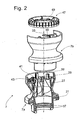
- the roll-off tube 7 consists of two bowl-shaped Individual elements 7a; 7b.
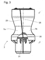
- a dividing joint 23 is parallel or preferred obliquely to the longitudinal axis 25 of the roll-off tube, as shown in FIG. 3 can be seen.
- stiffening ribs 27 At the inner wall of the individual elements may be integrally formed stiffening ribs 27, which preferably extend transversely to a dividing plane determined by the dividing joint.
- the roll tube consists of a urformbaren material, eg. B. an injection molded Plastic. In this orientation of the stiffening ribs, the individual elements be easily removed from the mold.
- FIG. 3 shows the mode of action of the axial support surface 31, which is designed like a finger is and a support web 35 of the single element 7b surrounds.
- the finger-like axial support surface 31 also acts as a radial holder to prevent the two drifting apart Preventing individual elements. From Fig. 2 it is further apparent that annular grooves 37 for the sealing rings 17 (corresponding to FIG. 1) are easy to produce.
- a securing means in Form arranged by at least one snap hook 39, which is the final assembly position secures the individual elements to each other. Furthermore, extend on the upper End face 41 axially extending pin 43, in the receptacles 45, the retaining webs 33 engage and thus enter into operative connection.
- the cones and the shots in Connection with the retaining webs also act as a radial holder, so that the individual elements can form a self-contained unit.
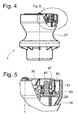
- Fixing ring 47 are used, with the effective as fastening means pin 43 occurs in operative connection by the pins 43 in the clamping openings 49 of the fixing ring 47 dive. So that the fixing ring is captive mountable, the pins provided with sawtooth-shaped locking catches 51.
- the roll-off tube 7 has a peripheral edge 51 on the inside with its together forms an annular channel 53 with the outside of the fixing ring 47.
- the rolling bellows 1 is inserted into the end of the ring channel, slipped over the edge 51, so that it can rest on the outer wall 19.
- the fixing ring 47 can then clamp the rollblag on the roll tube.
- FIG. 6 shows a cross section through the roll-off tube in the region of the constriction 21.
- FIG. 7 it can be seen that between the individual elements 7a; 7b arranged within the dividing joint sealing means 55, z. B. are molded as a soft component.
- the individual elements can also be welded or glued together be to prevent a pressure drop in the spring chamber.
Landscapes
- Engineering & Computer Science (AREA)
- General Engineering & Computer Science (AREA)
- Mechanical Engineering (AREA)
- Fluid-Damping Devices (AREA)
- Diaphragms And Bellows (AREA)
- Exhaust Gas After Treatment (AREA)
Abstract
Description
- Fig. 1
- Luftfeder in einer Gesamtschnittdarstellung
- Fig. 2
- Erfindungsgemäßes Abrollrohr für eine Luftfeder in einer Explosionsdarstellung
- Fig. 3
- Abrollrohr mit Teilausschnitt zur Darstellung einer Axialstützfläche
- Fig. 4
- Abrollrohr mit Darstellung der Wirkungsweise des Fixierrings
- Fig. 5
- Detaildarstellung zur Fig. 4
- Fig. 6
- Querschnittdarstellung zur Fig. 4
- Fig. 7
- Ausschnitt aus Fig. 6
Claims (16)
- Abrollrohr für eine Luftfeder,
dadurch gekennzeichnet, dass das Abrollrohr aus mindestens zwei schalenförmigen Einzelelementen (7a; 7b) besteht. - Abrollrohr nach Anspruch 1,
dadurch gekennzeichnet, dass mindestens eine Teilungsfuge (23) zwischen den Einzelelementen (7a; 7b) schräg zur Längsachse (25) verläuft. - Abrollrohr nach Anspruch 1,
dadurch gekennzeichnet, dass zwischen den Einzelelement (7a; 7b) Dichtmittel (55) angeordnet sind. - Abrollrohr nach Anspruch 3,
dadurch gekennzeichnet, dass die Dichtmittel (55) auf das Einzelelement (7a; 7b) aufgespritzt sind. - Abrollrohr nach Anspruch 1,
dadurch gekennzeichnet, dass ein Einzelelement (7a; 7b) mindestens eine Axialstützfläche(29; 31) für das mindestens eine weitere Einzelelement (7a; 7b) aufweist. - Abrollrohr nach Anspruch 1,
dadurch gekennzeichnet, dass mindestens ein Sicherungsmittel (39) an mindestens einem der Einzelelemente (7a; 7b) die Endmontageposition der Einzelelemente (7a; 7b) zueinander sichert. - Abrollrohr nach Anspruch 6,
dadurch gekennzeichnet, dass das Sicherungsmittel von mindestens einem Schnapphaken (39) gebildet wird, der an dem mindestens einen anderen Einzelelement (7a; 7b) angreift. - Abrollrohr nach Anspruch 1,
dadurch gekennzeichnet, dass ein Einzelelement (7a; 7b) mindestens einen Radialhalter (31) für das mindestens eine weitere Einzelelement (7a; 7b) aufweist. - Abrollrohr nach Anspruch 1,
dadurch gekennzeichnet, dass die Einzelelemente (7a; 7b) des Abrollrohrs von einem Fixierring (47) gesichert werden. - Abrollrohr nach Anspruch 9,
dadurch gekennzeichnet, dass mindestens eines der Einzelelemente (7a; 7b) Befestigungsmittel aufweist, die mit dem Fixierring (47) in Wirkverbindung treten. - Abrollrohr nach Anspruch 10,
dadurch gekennzeichnet, dass die Wirkverbindung von Zapfen (43) gebildet werden, die in Aufnahmen (49) eingreifen. - Abrollrohr nach Anspruch 11,
dadurch gekennzeichnet, dass die Zapfen(43) mit Sicherungsrasten (51) versehen sind. - Abrollrohr nach Anspruch 9,
dadurch gekennzeichnet, dass der Fixierring (47) eine Klemmkraft auf einen Rollbalg (3) der Luftfeder ausübt. - Abrollrohr nach Anspruch 13,
dadurch gekennzeichnet, dass das Abrollrohr (7) einen umlaufenden Rand (51) aufweist, über den der Rollbalg (3) gestülpt ist, wobei der Fixierring (47) den Rollbalg (3) am Abrollrohr (7) klemmt. - Abrollrohr nach Anspruch 1,
dadurch gekennzeichnet, dass die Einzelelemente (7a; 7b) miteinander verschweißt sind. - Abrollrohr nach Anspruch 1,
dadurch gekennzeichnet, dass die Einzelelemente (7a; 7b) miteinander verklebt sind.
Applications Claiming Priority (4)
| Application Number | Priority Date | Filing Date | Title |
|---|---|---|---|
| DE102004020211 | 2004-04-22 | ||
| DE102004020211 | 2004-04-22 | ||
| DE102004031873 | 2004-07-01 | ||
| DE102004031873A DE102004031873B3 (de) | 2004-04-22 | 2004-07-01 | Abrollrohr für einen Luftfederrollbalg |
Publications (2)
| Publication Number | Publication Date |
|---|---|
| EP1589253A1 true EP1589253A1 (de) | 2005-10-26 |
| EP1589253B1 EP1589253B1 (de) | 2006-11-15 |
Family
ID=34934901
Family Applications (1)
| Application Number | Title | Priority Date | Filing Date |
|---|---|---|---|
| EP05007728A Expired - Lifetime EP1589253B1 (de) | 2004-04-22 | 2005-04-08 | Luftfeder |
Country Status (5)
| Country | Link |
|---|---|
| US (1) | US20050236748A1 (de) |
| EP (1) | EP1589253B1 (de) |
| AT (1) | ATE345455T1 (de) |
| DE (2) | DE102004031873B3 (de) |
| ES (1) | ES2276366T3 (de) |
Cited By (4)
| Publication number | Priority date | Publication date | Assignee | Title |
|---|---|---|---|---|
| WO2015086315A1 (de) * | 2013-12-10 | 2015-06-18 | Trelleborgvibracoustic Gmbh | Luftfederkomponente |
| CN105365515A (zh) * | 2014-08-11 | 2016-03-02 | 现代摩比斯株式会社 | 车辆用空气弹簧的盖子及其制造方法 |
| WO2021138174A1 (en) * | 2019-12-31 | 2021-07-08 | Firestone Industrial Products Company, Llc | Gas spring and damper assemblies as well as suspension systems including same |
| WO2021138173A1 (en) * | 2019-12-31 | 2021-07-08 | Firestone Industrial Products Company, Llc | Gas spring and damper assemblies as well as suspension systems including same |
Families Citing this family (5)
| Publication number | Priority date | Publication date | Assignee | Title |
|---|---|---|---|---|
| US7500659B2 (en) * | 2005-04-07 | 2009-03-10 | Bfs Diversified Products, Llc | Air spring assembly and method |
| DE102006037034B4 (de) * | 2006-08-08 | 2009-01-02 | Saf-Holland Gmbh | Luftfeder für ein Fahrzeug |
| DE102011085323A1 (de) * | 2011-02-11 | 2012-08-16 | Continental Teves Ag & Co. Ohg | Kolben für eine Luftfeder |
| JP6438258B2 (ja) * | 2014-09-30 | 2018-12-12 | 株式会社ショーワ | 反力調整部材及びサスペンション |
| US10618366B2 (en) * | 2016-07-08 | 2020-04-14 | Continental Automotive Systems, Inc. | Vehicle air strut with twist lock closure cover |
Citations (4)
| Publication number | Priority date | Publication date | Assignee | Title |
|---|---|---|---|---|
| US2915088A (en) * | 1957-04-17 | 1959-12-01 | John V Felter | Seamed pipe of sheet material |
| US4502673A (en) * | 1982-02-11 | 1985-03-05 | Applied Power Inc. | Integral shock absorber and spring assembly |
| DE19522459C1 (de) * | 1995-06-21 | 1996-10-02 | Fichtel & Sachs Ag | Abdichtung eines Abrollrohres bei einer Luftfeder |
| DE10041927A1 (de) * | 1999-09-17 | 2001-03-22 | Phoenix Ag | Luftfederanordnung |
Family Cites Families (14)
| Publication number | Priority date | Publication date | Assignee | Title |
|---|---|---|---|---|
| US90572A (en) * | 1869-05-25 | Improvement in lamp-extinguishers | ||
| US128512A (en) * | 1872-07-02 | Improvement in churns | ||
| US5129634A (en) * | 1986-09-02 | 1992-07-14 | The Goodyear Tire & Rubber Company | Airspring with partial restraining sleeve |
| DE3824542A1 (de) * | 1988-07-20 | 1990-01-25 | Sauer Achsenfab | Tauchkolbenanordnung |
| DE8813045U1 (de) * | 1988-10-17 | 1988-12-29 | Fichtel & Sachs Ag, 97424 Schweinfurt | Luftfeder |
| DE3907462A1 (de) * | 1989-03-08 | 1990-09-13 | Continental Ag | Rollbalg-luftfeder |
| DE4135900C2 (de) * | 1991-10-31 | 1995-04-13 | Bayerische Motoren Werke Ag | Luftfeder, insbesondere für Kraftfahrzeuge |
| ES2122828B1 (es) * | 1993-11-03 | 1999-07-01 | Fichtel & Sachs Ag | Resorte neumatico |
| US5649691A (en) * | 1993-11-03 | 1997-07-22 | Fichtel & Sachs Ag | Shock absorber and pneumatic spring assembly |
| DE29608223U1 (de) * | 1996-05-07 | 1996-07-18 | Otto Sauer Achsenfabrik Keilberg, 63856 Bessenbach | Tauchkolbenanordnung |
| SE507531C2 (sv) * | 1996-10-28 | 1998-06-15 | Volvo Ab | Stötdämparanordning vid en hjulupphängning hos ett fordon |
| US6443436B1 (en) * | 2001-05-29 | 2002-09-03 | Tenneco Automotive Inc. | Air spring assembly on shock absorber with combined seal |
| DE10200553C1 (de) * | 2002-01-09 | 2003-07-31 | Zf Sachs Ag | Luftfeder mit integriertem Steuerventil |
| DE10242436A1 (de) * | 2002-09-11 | 2004-04-01 | Bpw Bergische Achsen Kg | Tauchkolben für eine Luftfeder |
-
2004
- 2004-07-01 DE DE102004031873A patent/DE102004031873B3/de not_active Expired - Fee Related
-
2005
- 2005-04-08 ES ES05007728T patent/ES2276366T3/es not_active Expired - Lifetime
- 2005-04-08 DE DE502005000185T patent/DE502005000185D1/de not_active Expired - Lifetime
- 2005-04-08 AT AT05007728T patent/ATE345455T1/de not_active IP Right Cessation
- 2005-04-08 EP EP05007728A patent/EP1589253B1/de not_active Expired - Lifetime
- 2005-04-21 US US11/111,448 patent/US20050236748A1/en not_active Abandoned
Patent Citations (4)
| Publication number | Priority date | Publication date | Assignee | Title |
|---|---|---|---|---|
| US2915088A (en) * | 1957-04-17 | 1959-12-01 | John V Felter | Seamed pipe of sheet material |
| US4502673A (en) * | 1982-02-11 | 1985-03-05 | Applied Power Inc. | Integral shock absorber and spring assembly |
| DE19522459C1 (de) * | 1995-06-21 | 1996-10-02 | Fichtel & Sachs Ag | Abdichtung eines Abrollrohres bei einer Luftfeder |
| DE10041927A1 (de) * | 1999-09-17 | 2001-03-22 | Phoenix Ag | Luftfederanordnung |
Cited By (8)
| Publication number | Priority date | Publication date | Assignee | Title |
|---|---|---|---|---|
| WO2015086315A1 (de) * | 2013-12-10 | 2015-06-18 | Trelleborgvibracoustic Gmbh | Luftfederkomponente |
| US10161472B2 (en) | 2013-12-10 | 2018-12-25 | Vibracoustic Gmbh | Air spring component |
| CN105365515A (zh) * | 2014-08-11 | 2016-03-02 | 现代摩比斯株式会社 | 车辆用空气弹簧的盖子及其制造方法 |
| CN105365515B (zh) * | 2014-08-11 | 2018-08-24 | 现代摩比斯株式会社 | 车辆用空气弹簧的盖子及其制造方法 |
| WO2021138174A1 (en) * | 2019-12-31 | 2021-07-08 | Firestone Industrial Products Company, Llc | Gas spring and damper assemblies as well as suspension systems including same |
| WO2021138173A1 (en) * | 2019-12-31 | 2021-07-08 | Firestone Industrial Products Company, Llc | Gas spring and damper assemblies as well as suspension systems including same |
| US11685214B2 (en) | 2019-12-31 | 2023-06-27 | Firestone Industrial Products Company, Llc | Gas spring and damper assemblies as well as suspension systems including same |
| US11859688B2 (en) | 2019-12-31 | 2024-01-02 | Firestone Industrial Products Company, Llc | Gas spring and damper assemblies as well as suspension systems including same |
Also Published As
| Publication number | Publication date |
|---|---|
| ATE345455T1 (de) | 2006-12-15 |
| DE502005000185D1 (de) | 2006-12-28 |
| EP1589253B1 (de) | 2006-11-15 |
| ES2276366T3 (es) | 2007-06-16 |
| DE102004031873B3 (de) | 2005-11-17 |
| US20050236748A1 (en) | 2005-10-27 |
Similar Documents
| Publication | Publication Date | Title |
|---|---|---|
| EP2070738B1 (de) | Kolben-Zylinderaggregat mit einem Kolbenstangenschutz | |
| DE102007004037B4 (de) | Anordnung eines Faltenbalgs als Schutzmanschette an einer Luftfeder | |
| DE10122796B4 (de) | Kolben-Zylinderaggregat mit einem Faltbalg | |
| DE1500257C2 (de) | Rückschlagventil für Rohrleitungen | |
| DE7718677U1 (de) | Federelement, insbesondere zur elastischen Lagerung von Antriebs- oder sonstigen Aggregaten in Kraftfahrzeugen | |
| EP0651177B1 (de) | Schwingungstilger | |
| EP3408556B1 (de) | Luftfeder mit faltenbalg | |
| DE2816742C2 (de) | ||
| DE102011051013A1 (de) | Vorrichtung zur Befestigung eines Anbauteils, zum Beispiel einer Reling, an einer Fahrzeugkarosserie | |
| DE202013011533U1 (de) | Ringförmige Steckkupplung sowie ein Herstellungs- und ein Verbindungsverfahren dafür | |
| DE2952176A1 (de) | Fuehrungslenker fuer radaufhaengungen von kraftfahrzeugen | |
| DE102004031873B3 (de) | Abrollrohr für einen Luftfederrollbalg | |
| DE202014008476U1 (de) | Radsatzwellenschutz | |
| DE10163818B4 (de) | Schlauchrollbalg-Feder | |
| DE102016200307A1 (de) | Federteller für einen Schwingungsdämpfer | |
| EP1546574B1 (de) | Tauchkolben f r eine luftfeder | |
| DE102012213275A1 (de) | Federbeinstützlager | |
| EP3498504A1 (de) | Federlenker für eine radaufhängung eines kraftfahrzeuges | |
| DE102005008045B3 (de) | Kolben-Zylinderaggregat mit einem Schutzrohr | |
| DE10126680C1 (de) | Lagerung für ein Federbein | |
| DE60309066T2 (de) | Flanschverbindung und verfahren zur befestigung einer gasfeder | |
| DE2943137A1 (de) | Radblende, insbesondere fuer die raeder von personenkraftwagen | |
| EP0327810A2 (de) | Gummilager für Federn, Achsen und ähnliche Teile an Kraftfahrzeugen | |
| DE29521734U1 (de) | Gleitringdichtung | |
| EP1852617B1 (de) | Einrichtung zur Befestigung eines Dichtungsbalgs |
Legal Events
| Date | Code | Title | Description |
|---|---|---|---|
| PUAI | Public reference made under article 153(3) epc to a published international application that has entered the european phase |
Free format text: ORIGINAL CODE: 0009012 |
|
| 17P | Request for examination filed |
Effective date: 20050809 |
|
| AK | Designated contracting states |
Kind code of ref document: A1 Designated state(s): AT BE BG CH CY CZ DE DK EE ES FI FR GB GR HU IE IS IT LI LT LU MC NL PL PT RO SE SI SK TR |
|
| AX | Request for extension of the european patent |
Extension state: AL BA HR LV MK YU |
|
| GRAP | Despatch of communication of intention to grant a patent |
Free format text: ORIGINAL CODE: EPIDOSNIGR1 |
|
| RTI1 | Title (correction) |
Free format text: GAS SPRING |
|
| AKX | Designation fees paid |
Designated state(s): AT BE BG CH CY CZ DE DK EE ES FI FR GB GR HU IE IS IT LI LT LU MC NL PL PT RO SE SI SK TR |
|
| GRAS | Grant fee paid |
Free format text: ORIGINAL CODE: EPIDOSNIGR3 |
|
| GRAA | (expected) grant |
Free format text: ORIGINAL CODE: 0009210 |
|
| AK | Designated contracting states |
Kind code of ref document: B1 Designated state(s): AT BE BG CH CY CZ DE DK EE ES FI FR GB GR HU IE IS IT LI LT LU MC NL PL PT RO SE SI SK TR |
|
| PG25 | Lapsed in a contracting state [announced via postgrant information from national office to epo] |
Ref country code: IT Free format text: LAPSE BECAUSE OF FAILURE TO SUBMIT A TRANSLATION OF THE DESCRIPTION OR TO PAY THE FEE WITHIN THE PRESCRIBED TIME-LIMIT;WARNING: LAPSES OF ITALIAN PATENTS WITH EFFECTIVE DATE BEFORE 2007 MAY HAVE OCCURRED AT ANY TIME BEFORE 2007. THE CORRECT EFFECTIVE DATE MAY BE DIFFERENT FROM THE ONE RECORDED. Effective date: 20061115 Ref country code: SI Free format text: LAPSE BECAUSE OF FAILURE TO SUBMIT A TRANSLATION OF THE DESCRIPTION OR TO PAY THE FEE WITHIN THE PRESCRIBED TIME-LIMIT Effective date: 20061115 Ref country code: CZ Free format text: LAPSE BECAUSE OF FAILURE TO SUBMIT A TRANSLATION OF THE DESCRIPTION OR TO PAY THE FEE WITHIN THE PRESCRIBED TIME-LIMIT Effective date: 20061115 Ref country code: RO Free format text: LAPSE BECAUSE OF FAILURE TO SUBMIT A TRANSLATION OF THE DESCRIPTION OR TO PAY THE FEE WITHIN THE PRESCRIBED TIME-LIMIT Effective date: 20061115 Ref country code: NL Free format text: LAPSE BECAUSE OF FAILURE TO SUBMIT A TRANSLATION OF THE DESCRIPTION OR TO PAY THE FEE WITHIN THE PRESCRIBED TIME-LIMIT Effective date: 20061115 Ref country code: IE Free format text: LAPSE BECAUSE OF FAILURE TO SUBMIT A TRANSLATION OF THE DESCRIPTION OR TO PAY THE FEE WITHIN THE PRESCRIBED TIME-LIMIT Effective date: 20061115 Ref country code: PL Free format text: LAPSE BECAUSE OF FAILURE TO SUBMIT A TRANSLATION OF THE DESCRIPTION OR TO PAY THE FEE WITHIN THE PRESCRIBED TIME-LIMIT Effective date: 20061115 Ref country code: LT Free format text: LAPSE BECAUSE OF FAILURE TO SUBMIT A TRANSLATION OF THE DESCRIPTION OR TO PAY THE FEE WITHIN THE PRESCRIBED TIME-LIMIT Effective date: 20061115 Ref country code: FI Free format text: LAPSE BECAUSE OF FAILURE TO SUBMIT A TRANSLATION OF THE DESCRIPTION OR TO PAY THE FEE WITHIN THE PRESCRIBED TIME-LIMIT Effective date: 20061115 Ref country code: SK Free format text: LAPSE BECAUSE OF FAILURE TO SUBMIT A TRANSLATION OF THE DESCRIPTION OR TO PAY THE FEE WITHIN THE PRESCRIBED TIME-LIMIT Effective date: 20061115 |
|
| REG | Reference to a national code |
Ref country code: GB Ref legal event code: FG4D Free format text: NOT ENGLISH |
|
| REG | Reference to a national code |
Ref country code: CH Ref legal event code: EP |
|
| REF | Corresponds to: |
Ref document number: 502005000185 Country of ref document: DE Date of ref document: 20061228 Kind code of ref document: P |
|
| REG | Reference to a national code |
Ref country code: IE Ref legal event code: FG4D Free format text: LANGUAGE OF EP DOCUMENT: GERMAN |
|
| PG25 | Lapsed in a contracting state [announced via postgrant information from national office to epo] |
Ref country code: DK Free format text: LAPSE BECAUSE OF FAILURE TO SUBMIT A TRANSLATION OF THE DESCRIPTION OR TO PAY THE FEE WITHIN THE PRESCRIBED TIME-LIMIT Effective date: 20070215 Ref country code: BG Free format text: LAPSE BECAUSE OF FAILURE TO SUBMIT A TRANSLATION OF THE DESCRIPTION OR TO PAY THE FEE WITHIN THE PRESCRIBED TIME-LIMIT Effective date: 20070215 |
|
| REG | Reference to a national code |
Ref country code: SE Ref legal event code: TRGR |
|
| PG25 | Lapsed in a contracting state [announced via postgrant information from national office to epo] |
Ref country code: IS Free format text: LAPSE BECAUSE OF FAILURE TO SUBMIT A TRANSLATION OF THE DESCRIPTION OR TO PAY THE FEE WITHIN THE PRESCRIBED TIME-LIMIT Effective date: 20070315 |
|
| PGFP | Annual fee paid to national office [announced via postgrant information from national office to epo] |
Ref country code: SE Payment date: 20070404 Year of fee payment: 3 |
|
| PG25 | Lapsed in a contracting state [announced via postgrant information from national office to epo] |
Ref country code: PT Free format text: LAPSE BECAUSE OF FAILURE TO SUBMIT A TRANSLATION OF THE DESCRIPTION OR TO PAY THE FEE WITHIN THE PRESCRIBED TIME-LIMIT Effective date: 20070416 |
|
| NLV1 | Nl: lapsed or annulled due to failure to fulfill the requirements of art. 29p and 29m of the patents act | ||
| PGFP | Annual fee paid to national office [announced via postgrant information from national office to epo] |
Ref country code: ES Payment date: 20070521 Year of fee payment: 3 |
|
| ET | Fr: translation filed | ||
| GBV | Gb: ep patent (uk) treated as always having been void in accordance with gb section 77(7)/1977 [no translation filed] |
Effective date: 20061115 |
|
| REG | Reference to a national code |
Ref country code: ES Ref legal event code: FG2A Ref document number: 2276366 Country of ref document: ES Kind code of ref document: T3 |
|
| REG | Reference to a national code |
Ref country code: IE Ref legal event code: FD4D |
|
| PLBE | No opposition filed within time limit |
Free format text: ORIGINAL CODE: 0009261 |
|
| STAA | Information on the status of an ep patent application or granted ep patent |
Free format text: STATUS: NO OPPOSITION FILED WITHIN TIME LIMIT |
|
| 26N | No opposition filed |
Effective date: 20070817 |
|
| PG25 | Lapsed in a contracting state [announced via postgrant information from national office to epo] |
Ref country code: GB Free format text: LAPSE BECAUSE OF FAILURE TO SUBMIT A TRANSLATION OF THE DESCRIPTION OR TO PAY THE FEE WITHIN THE PRESCRIBED TIME-LIMIT Effective date: 20061115 |
|
| BERE | Be: lapsed |
Owner name: ZF FRIEDRICHSHAFEN A.G. Effective date: 20070430 |
|
| PG25 | Lapsed in a contracting state [announced via postgrant information from national office to epo] |
Ref country code: BE Free format text: LAPSE BECAUSE OF NON-PAYMENT OF DUE FEES Effective date: 20070430 |
|
| PG25 | Lapsed in a contracting state [announced via postgrant information from national office to epo] |
Ref country code: GR Free format text: LAPSE BECAUSE OF FAILURE TO SUBMIT A TRANSLATION OF THE DESCRIPTION OR TO PAY THE FEE WITHIN THE PRESCRIBED TIME-LIMIT Effective date: 20070216 |
|
| PGFP | Annual fee paid to national office [announced via postgrant information from national office to epo] |
Ref country code: FR Payment date: 20070411 Year of fee payment: 3 |
|
| PG25 | Lapsed in a contracting state [announced via postgrant information from national office to epo] |
Ref country code: AT Free format text: LAPSE BECAUSE OF NON-PAYMENT OF DUE FEES Effective date: 20070408 |
|
| EUG | Se: european patent has lapsed | ||
| PG25 | Lapsed in a contracting state [announced via postgrant information from national office to epo] |
Ref country code: EE Free format text: LAPSE BECAUSE OF FAILURE TO SUBMIT A TRANSLATION OF THE DESCRIPTION OR TO PAY THE FEE WITHIN THE PRESCRIBED TIME-LIMIT Effective date: 20061115 |
|
| REG | Reference to a national code |
Ref country code: FR Ref legal event code: ST Effective date: 20081231 |
|
| PG25 | Lapsed in a contracting state [announced via postgrant information from national office to epo] |
Ref country code: MC Free format text: LAPSE BECAUSE OF NON-PAYMENT OF DUE FEES Effective date: 20070430 |
|
| PG25 | Lapsed in a contracting state [announced via postgrant information from national office to epo] |
Ref country code: FR Free format text: LAPSE BECAUSE OF NON-PAYMENT OF DUE FEES Effective date: 20080430 |
|
| REG | Reference to a national code |
Ref country code: ES Ref legal event code: FD2A Effective date: 20080409 |
|
| PG25 | Lapsed in a contracting state [announced via postgrant information from national office to epo] |
Ref country code: ES Free format text: LAPSE BECAUSE OF NON-PAYMENT OF DUE FEES Effective date: 20080409 |
|
| PG25 | Lapsed in a contracting state [announced via postgrant information from national office to epo] |
Ref country code: LU Free format text: LAPSE BECAUSE OF NON-PAYMENT OF DUE FEES Effective date: 20070408 Ref country code: CY Free format text: LAPSE BECAUSE OF FAILURE TO SUBMIT A TRANSLATION OF THE DESCRIPTION OR TO PAY THE FEE WITHIN THE PRESCRIBED TIME-LIMIT Effective date: 20061115 |
|
| PG25 | Lapsed in a contracting state [announced via postgrant information from national office to epo] |
Ref country code: HU Free format text: LAPSE BECAUSE OF FAILURE TO SUBMIT A TRANSLATION OF THE DESCRIPTION OR TO PAY THE FEE WITHIN THE PRESCRIBED TIME-LIMIT Effective date: 20070516 Ref country code: TR Free format text: LAPSE BECAUSE OF FAILURE TO SUBMIT A TRANSLATION OF THE DESCRIPTION OR TO PAY THE FEE WITHIN THE PRESCRIBED TIME-LIMIT Effective date: 20061115 |
|
| REG | Reference to a national code |
Ref country code: CH Ref legal event code: PL |
|
| PG25 | Lapsed in a contracting state [announced via postgrant information from national office to epo] |
Ref country code: CH Free format text: LAPSE BECAUSE OF NON-PAYMENT OF DUE FEES Effective date: 20090430 Ref country code: LI Free format text: LAPSE BECAUSE OF NON-PAYMENT OF DUE FEES Effective date: 20090430 |
|
| PG25 | Lapsed in a contracting state [announced via postgrant information from national office to epo] |
Ref country code: SE Free format text: LAPSE BECAUSE OF NON-PAYMENT OF DUE FEES Effective date: 20080409 |
|
| PGFP | Annual fee paid to national office [announced via postgrant information from national office to epo] |
Ref country code: DE Payment date: 20130403 Year of fee payment: 9 |
|
| REG | Reference to a national code |
Ref country code: DE Ref legal event code: R119 Ref document number: 502005000185 Country of ref document: DE |
|
| REG | Reference to a national code |
Ref country code: DE Ref legal event code: R119 Ref document number: 502005000185 Country of ref document: DE Effective date: 20141101 |
|
| PG25 | Lapsed in a contracting state [announced via postgrant information from national office to epo] |
Ref country code: DE Free format text: LAPSE BECAUSE OF NON-PAYMENT OF DUE FEES Effective date: 20141101 |