EP1589234A1 - Befestigungseinheit - Google Patents
Befestigungseinheit Download PDFInfo
- Publication number
- EP1589234A1 EP1589234A1 EP04009660A EP04009660A EP1589234A1 EP 1589234 A1 EP1589234 A1 EP 1589234A1 EP 04009660 A EP04009660 A EP 04009660A EP 04009660 A EP04009660 A EP 04009660A EP 1589234 A1 EP1589234 A1 EP 1589234A1
- Authority
- EP
- European Patent Office
- Prior art keywords
- attachment
- load
- fastening
- fastening unit
- unit according
- Prior art date
- Legal status (The legal status is an assumption and is not a legal conclusion. Google has not performed a legal analysis and makes no representation as to the accuracy of the status listed.)
- Granted
Links
- 239000004567 concrete Substances 0.000 claims abstract description 12
- 239000000463 material Substances 0.000 claims description 12
- 239000011449 brick Substances 0.000 abstract 1
- 238000013461 design Methods 0.000 description 10
- 229910000831 Steel Inorganic materials 0.000 description 8
- 239000010959 steel Substances 0.000 description 8
- 230000003068 static effect Effects 0.000 description 6
- 238000011161 development Methods 0.000 description 5
- 230000018109 developmental process Effects 0.000 description 5
- 238000010276 construction Methods 0.000 description 4
- 238000005516 engineering process Methods 0.000 description 3
- 238000000034 method Methods 0.000 description 3
- 238000013459 approach Methods 0.000 description 2
- 230000008901 benefit Effects 0.000 description 2
- 238000009434 installation Methods 0.000 description 2
- 230000002028 premature Effects 0.000 description 2
- 241000163925 Bembidion minimum Species 0.000 description 1
- XAGFODPZIPBFFR-UHFFFAOYSA-N aluminium Chemical compound [Al] XAGFODPZIPBFFR-UHFFFAOYSA-N 0.000 description 1
- 229910052782 aluminium Inorganic materials 0.000 description 1
- 238000004873 anchoring Methods 0.000 description 1
- 239000002131 composite material Substances 0.000 description 1
- 230000001419 dependent effect Effects 0.000 description 1
- 238000006073 displacement reaction Methods 0.000 description 1
- 230000000694 effects Effects 0.000 description 1
- 230000005489 elastic deformation Effects 0.000 description 1
- 230000000977 initiatory effect Effects 0.000 description 1
- 238000003780 insertion Methods 0.000 description 1
- 230000037431 insertion Effects 0.000 description 1
- 230000003993 interaction Effects 0.000 description 1
- 238000011835 investigation Methods 0.000 description 1
- 239000004570 mortar (masonry) Substances 0.000 description 1
- 238000004382 potting Methods 0.000 description 1
- 239000011150 reinforced concrete Substances 0.000 description 1
- 230000002787 reinforcement Effects 0.000 description 1
- 230000007704 transition Effects 0.000 description 1
Images

Classifications
-
- F—MECHANICAL ENGINEERING; LIGHTING; HEATING; WEAPONS; BLASTING
- F16—ENGINEERING ELEMENTS AND UNITS; GENERAL MEASURES FOR PRODUCING AND MAINTAINING EFFECTIVE FUNCTIONING OF MACHINES OR INSTALLATIONS; THERMAL INSULATION IN GENERAL
- F16B—DEVICES FOR FASTENING OR SECURING CONSTRUCTIONAL ELEMENTS OR MACHINE PARTS TOGETHER, e.g. NAILS, BOLTS, CIRCLIPS, CLAMPS, CLIPS OR WEDGES; JOINTS OR JOINTING
- F16B5/00—Joining sheets or plates, e.g. panels, to one another or to strips or bars parallel to them
- F16B5/02—Joining sheets or plates, e.g. panels, to one another or to strips or bars parallel to them by means of fastening members using screw-thread
-
- E—FIXED CONSTRUCTIONS
- E04—BUILDING
- E04B—GENERAL BUILDING CONSTRUCTIONS; WALLS, e.g. PARTITIONS; ROOFS; FLOORS; CEILINGS; INSULATION OR OTHER PROTECTION OF BUILDINGS
- E04B1/00—Constructions in general; Structures which are not restricted either to walls, e.g. partitions, or floors or ceilings or roofs
- E04B1/18—Structures comprising elongated load-supporting parts, e.g. columns, girders, skeletons
- E04B1/24—Structures comprising elongated load-supporting parts, e.g. columns, girders, skeletons the supporting parts consisting of metal
- E04B1/2403—Connection details of the elongated load-supporting parts
- E04B2001/2415—Brackets, gussets, joining plates
-
- E—FIXED CONSTRUCTIONS
- E04—BUILDING
- E04B—GENERAL BUILDING CONSTRUCTIONS; WALLS, e.g. PARTITIONS; ROOFS; FLOORS; CEILINGS; INSULATION OR OTHER PROTECTION OF BUILDINGS
- E04B1/00—Constructions in general; Structures which are not restricted either to walls, e.g. partitions, or floors or ceilings or roofs
- E04B1/18—Structures comprising elongated load-supporting parts, e.g. columns, girders, skeletons
- E04B1/24—Structures comprising elongated load-supporting parts, e.g. columns, girders, skeletons the supporting parts consisting of metal
- E04B1/2403—Connection details of the elongated load-supporting parts
- E04B2001/2442—Connections with built-in weakness points
Definitions
- the present invention relates to a fastening unit for fixing objects to a structural section concrete, masonry or the like, or for connection of structural sections, under dynamic loading, according to the preamble of claim 1.
- Fasteners such as dowels, headed bolts, anchor channels, So-called concrete screws or the like can be found in construction wide application. They are on the one hand for attachment light or heavy objects such as piping, Machine parts, air conditioners, lighting etc. at concrete or Masonry structures used, but also on the other hand for connecting structural sections made of concrete, masonry or the like used.
- the invention is based on the idea, a Mounting unit of one or more Fasteners and an attachment so to design that a failure of one or even more Fasteners largely excluded from the outset is, without being complicated in each individual case extensive investigations are required.
- the attachment such that at each individual or combined load in at least two Load directions the elastic load capacity of the Attachment is at least partially exceeded, before the maximum load capacity of a fastener or all fasteners is reached.
- the invention eliminates Fastening unit the need that in each Case by case a complicated and expensive design for dynamic loads must be carried out, and eliminated thereby also considerable sources of error, which individual case assessment is unavoidable. It is also too Note that attachment units for seismic Applications are often high in safety relevant facilities are used, such as (Nuclear) power plants, public buildings and the like.
- a fastener further increase and larger
- the attachment such that at each individual or combined load in at least two Load directions the elastic load capacity of the Attachment is at least partially exceeded, before the elastic load capacity of a fastener or all fasteners is reached.
- the at least one Fastening element in case of dynamic stress none undergoes non-elastic deformations, so a Replace or renovate the at least one Fastener after passing through the dynamic Load is not required. Accordingly, it is enough regularly, only in the course of dynamic demands possibly heavily deformed attachment to replace what can be carried out inexpensively and quickly.
- the terms "elastic Load capacity or maximum load capacity refers to Points in the load shift curve of a Fastening element or an attachment that in a certain direction is charged. It describes the elastic load capacity the transition of the load-displacement curve from a linear to a nonlinear one Course, while the maximum carrying capacity that point describes at which the highest load is reached.
- ductile components such as For example, attachments made of steel
- the attachment after Exceeding the elastic load capacity depending on Ductility of the material used to considerable additional deformations until reaching the elongation at break can be able.
- the attachment at least partially made of a ductile material, d. H. a material which, after exceeding its elastic Carrying capacity allows considerable further deformations. On this way can be a complete break of the Mounting unit, for example, to a Falling down attached objects can be avoided become.
- the orientation of the individual load directions leaves advance in a variety of ways to the respective Combination of attachment, fasteners, anchor and and adjust the installation situation if necessary.
- the Load directions a first load direction, which is substantially perpendicular to the axis of the first Fastener extends, and a second Loading direction, which is substantially perpendicular to the first load direction and / or the axis of the first Fastening element extends, have. This will Achieved that even with multi-axial transverse load, as they When earthquakes occur frequently, a failure of at least a fastener is excluded.
- the Loading directions also a third load direction include perpendicular to the first and / or second loading direction and preferably substantially parallel to the axis of the first fastener extends. In this way is also combined, train and Queryakbe pipeung the at least one Fastening element failure of the same excluded.
- the attachment according to the invention can basically with a any number of fasteners combined be, for example, with a single Fastener. For absorbing dynamic loads and it is to avoid twisting the attachment
- at least two Fasteners are provided.
- the attachment at least two Has passage openings.
- the Loading directions preferably a first loading direction, which is substantially perpendicular to the axis of the first Fastener extends, and a second Loading direction, which is essentially in the direction in the at least two passage openings next to each other are arranged, and / or substantially perpendicular to the first loading direction extends to.
- the present The invention thus provides an attachment in which even in the direction in which known attachments a have undesirably high rigidity, the desired Ensures ductility and thus premature failure a fastener is excluded.
- the Attachment be designed in a variety of ways. According to one embodiment of the present invention, it is however, it is preferred that the attachment be a first section for connection to the at least one fastening element, a second section for connection to at least one to be fastened component, and a third section, which connects the first and the second section, having the elastic load capacity of the third Section less in at least one direction of loading is as that of the first and / or second section.
- the third section in any Loading direction, the load capacity of the attachment so to agree that an overload of the at least one Fastener is excluded, which in known Attachments was not possible.
- the third section is integral with the first and / or second section may be formed, or even a may be separate, possibly multi-part element, which connects the first and the second section.
- the third section the most diverse Materials and geometries in question, as long as they are the fulfill the desired function. In a particularly simple way If the third section can be configured according to the invention, by having a smaller cross-section than the first and / or second section.
- the first section of the attachment a Device for reducing slippage, in particular Hole play, compared to at least one fastener having. This will ensure that the actually carrying capacity of at least one Fastener or all fasteners not is reduced by unwanted slippage and thereby a early failure of at least one Fastening element occurs. It should be noted that between the attachment and the at least one Fastening element of the fastening unit according to the invention Usually a certain hole play is present to the Allow installation of the individual components before this be permanently clamped together.
- the present Invention to an attachment for attachment of objects a structural section of concrete, masonry or the like, or for connecting structural sections, under dynamic load ready, provided for that purpose is, by means of at least one in the structural section anchorable fastener with the structural section be connected, and that is dimensioned so that at each single or combined load in at least two load directions the elastic load capacity of the Attachment is at least partially exceeded, before the maximum load capacity of a fastener or all fasteners is reached.
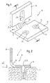
- Fig. 1 shows schematically a perspective view of a Attachment 10 according to a first embodiment of present invention.
- the attachment 10 is generally L-shaped formed and has a first, plate-like Section 16, a second, plate-like section 18th and a web connecting them 20.
- the attachment exists in the present embodiment of steel, however also consist of other suitable materials, such as for example aluminum. These are ductile materials prefers.
- the first section 16 of the attachment 10 comprises in the present embodiment, two through holes 12, 14, for passing fasteners, such as For example, dowels, concrete screws or the like serve.
- fasteners such as For example, dowels, concrete screws or the like serve.
- only one Through hole or multiple through holes for Fastening means can be provided.
- second section 18 of the attachment 10 a single, slot-like through hole 26 is provided, which also for passing through fasteners.
- Fig. 2 schematically shows a lateral Sectional view of the attachment shown in Fig. 1 shows, the section taken along the line II-II in Fig. 1 is.
- the attachment 10 by means of two dowels 2, 4th attached to a structural section T and forms with these a fastening unit according to the invention 1.
- the Structural section T can be made of reinforced concrete or may consist of another suitable structural material
- T is also a steel construction or a Composite construction act, in these cases the Fasteners 2, 4 are to be selected accordingly.
- the plate-shaped second section 18 can any object such as piping, machine parts, Air conditioners, lighting and the like are attached, for example, by conventional screws or bolts through the passage opening 26 passed and with the Attachment 10 are clamped.
- another Attach structural section such as Prefabricated or semi-finished parts for walls, columns and like.
- the web 20 of the Attachment 10 a significantly smaller cross-section than the plate-shaped portions 16 and 18, so that the web 20 in the present embodiment, a much lower Carrying capacity and rigidity has as the sections 16th and 18.
- This in particular avoids that the Attachment 10, for example, at loads in the in Fig. 1st specified Y-direction excessive rigidity and Has strength that does not have sufficient Deformability under dynamic loads would allow.
- the plate-shaped sections 16 and 18 often due constructive specifications, such.
- Minimum distances of Fastener or design of the to be fastened Items that have great dimensions are for use under dynamic, in particular seismic stress to stiff and therefore not suitable.
- an attachment is made by the present invention 10 provides any connection geometry to fastening components or structures with a bearing behavior united, for dynamic, especially seismic Stress is suitable. So is the carrying behavior of the Attachment 10 according to the invention on the Fasteners 2 and 4 designed that elastic Load capacity of the attachment 10 in the region of the web 20 in at least two load directions is less than that elastic load capacity of the fastening elements through the second and 4 formed group. As elastic load capacity of Steges 20 is the load referred to, at which at least partially the material of the web 20 reached the yield point.
- the reduced load capacity of the web 20 is in the present embodiment by a reduced Cross-sectional area achieved.
- other Measures to reduce the carrying capacity of the section 20 are possible, such as the use of another Material or the like.
- FIG. 3 shows schematically different views of a second Embodiment of the attachment according to the invention.
- Fig. 3 purely exemplary dimensions in mm for the Attachment 10 indicated that in no way limiting for the present invention are.
- the shown in Fig. 3 Attachment 10 differs from that in FIGS. 1 and 2 Attachment shown mainly in that the third Section 20 by two spaced apart Part sections 20 ', 20 "is formed.
- the third Section 20 by two spaced apart Part sections 20 ', 20 "is formed.
- the carrying capacity of the fixture 10 even better on the Load capacity, number, arrangement etc. of Fasteners and other boundary conditions be matched.
- the attachment 10 is suitable to be used in the present embodiment, for example, with two dowels type Würth W-HAZ-B size M12 (steel grade 8.8) as a fastening unit 1 according to the invention.
- FIG Attachment 10 also with other fasteners a Forming unit according to the invention can form as long as the in the claims specified conditions and features are fulfilled.
- This also results from a basic idea of the invention, according to which not an attachment to the combination is limited to a particular fastener, but certain, inventive combinations of Attachments and fasteners always ensure that a (brittle) failure of the fasteners by the Design of the attachment is excluded.
- the inventors have a non-linear computer computation the basis of the finite element method.
- the attachment 10 was in the range the through holes 12, 14 held immovably, and the second section 18 was in the area of his Through hole with a load in each X-, Y- and Z direction acted upon.
- the load was increased until at least at one location of the attachment 10 the characteristic yield strength of the material exceeded and finally reached the breaking elongation of the material has been.
- the location of the start of flow was always in the third section 20 of the fixture 10th
- the difference between load at start of flow and tensile stress of the anchor group in the X direction is due to the fact that the attachment is supported on the anchoring ground under tensile stress, resulting in an additional load (here in the amount of 3 kN) of the anchor group.
- the attachment according to the invention or the Mounting unit according to the invention that the design an attachment for dynamic, especially seismic Stresses in a simple and secure way can be made.
- the load-bearing and deformation behavior the attachment is according to the invention already on the matched at least one fastener that the scheduling engineer no nonlinear and / or dynamic Analyzes must perform, but the attachment in principle as in static load cases can make.
Landscapes
- Engineering & Computer Science (AREA)
- General Engineering & Computer Science (AREA)
- Mechanical Engineering (AREA)
- Joining Of Building Structures In Genera (AREA)
- Basic Packing Technique (AREA)
- Seal Device For Vehicle (AREA)
- Paper (AREA)
- Connection Of Plates (AREA)
- Led Device Packages (AREA)
- Polarising Elements (AREA)
- Liquid Developers In Electrophotography (AREA)
Abstract
Description
alternativ a) derart ausgelegt werden, dass "duktiles" Stahlversagen des Befestigungselements selbst maßgebend wird, oder b) in Verbindung mit einem Anbauteil eingesetzt werden, das "duktil" versagt, bevor die Tragfähigkeit des Befestigungselements erreicht ist.
- Fig. 1
- zeigt schematisch eine Perspektivansicht einer ersten Ausführungsform des erfindungsgemäßen Anbauteils;
- Fig. 2
- zeigt schematisch eine seitliche Schnittansicht einer ersten Ausführungsform der erfindungsgemäßen Befestigungseinheit, wobei der Schnitt entlang der Linie II-II in Fig. 1 geführt ist;
- Fig. 3
- zeigt schematisch verschiedene Ansichten einer zweiten Ausführungsform des erfindungsgemäßen Anbauteils;

Claims (13)
- Befestigungseinheit (1) zur Befestigung von Gegenständen an einem Tragwerksabschnitt (T) aus Beton, Mauerwerk oder dergleichen, oder zur Verbindung von Tragwerksabschnitten (T), unter dynamischer Beanspruchung, mit
mindestens einem Befestigungselement (2, 4), das in dem Tragwerksabschnitt (T) verankerbar ist, und
einem Anbauteil (10), das dazu vorgesehen ist, mittels des mindestens einen Befestigungselements (2, 4) mit dem Tragwerksabschnitt (T) verbunden zu werden,
dadurch gekennzeichnet, dass das Anbauteil (10) derart bemessen ist, dass bei jeweils einzelner oder kombinierter Belastung in mindestens zwei Belastungsrichtungen (X, Y, Z) die elastische Tragfähigkeit (RA) des Anbauteils zumindest abschnittsweise überschritten wird, bevor die Maximaltragfähigkeit eines Befestigungselements oder aller Befestigungselemente (2, 4) erreicht ist. - Befestigungseinheit nach Anspruch 1, dadurch gekennzeichnet, dass das Anbauteil (10) derart bemessen ist, dass bei jeweils einzelner oder kombinierter Belastung in mindestens zwei Belastungsrichtungen (X, Y, Z) die elastische Tragfähigkeit (RA) des Anbauteils zumindest abschnittsweise überschritten wird, bevor die elastische Tragfähigkeit (RX, RY, RZ) eines Befestigungselements oder aller Befestigungselemente (2, 4) erreicht ist.
- Befestigungseinheit nach Anspruch 1 oder 2, dadurch gekennzeichnet, dass die Anzahl der Belastungsrichtungen (X, Y, Z) drei beträgt.
- Befestigungseinheit nach einem der vorhergehenden Ansprüche, dadurch gekennzeichnet, dass die Belastungsrichtungen eine erste Belastungsrichtung (X), die sich im wesentlichen senkrecht zu der Achse des ersten Befestigungselements (2) erstreckt, und eine zweite Belastungsrichtung (Y), die sich im wesentlichen senkrecht zu der ersten Belastungsrichtung (X) und/oder der Achse des ersten Befestigungselements (2) erstreckt, aufweisen.
- Befestigungseinheit nach Anspruch 4, dadurch gekennzeichnet, dass die Belastungsrichtungen ferner eine dritte Belastungsrichtung (Z) einschließen, die sich senkrecht zu der ersten (X) und/oder zweiten (Y) Belastungsrichtung und bevorzugt im wesentlichen parallel zu der Achse des ersten Befestigungselements (2) erstreckt.
- Befestigungseinheit nach einem der vorhergehenden Ansprüche, dadurch gekennzeichnet, dass das Anbauteil (10) mindestens zwei Durchgangsöffnungen (12, 14) aufweist, wobei die Belastungsrichtungen eine erste Belastungsrichtung (X), die sich im wesentlichen senkrecht zu der Achse des ersten Befestigungselements (2) erstreckt, und eine zweite Belastungsrichtung (Y), die sich im wesentlichen in der Richtung, in der mindestens zwei Durchgangsöffnungen (12, 14) nebeneinander angeordnet sind, und/oder im wesentlichen senkrecht zu der ersten Belastungsrichtung (X) erstreckt, aufweisen.
- Befestigungseinheit nach einem der vorhergehenden Ansprüche, dadurch gekennzeichnet, dass das Anbauteil (10) einen ersten Abschnitt (16) zur Verbindung mit dem mindestens einen Befestigungselement (2, 4), einen zweiten Abschnitt (18) zur Verbindung mit mindestens einem zu befestigenden Bauteil, und einen dritten Abschnitt (20), welcher den ersten und den zweiten Abschnitt verbindet, aufweist, wobei die elastische Tragfähigkeit des dritten Abschnitts (20) in mindestens einer Belastungsrichtung geringer ist als diejenige des ersten und/oder zweiten Abschnitts (16, 18).
- Befestigungseinheit nach Anspruch 7, dadurch gekennzeichnet, dass der dritte Abschnitt (20) einen geringeren Querschnitt aufweist als der erste und/oder zweite Abschnitt (16, 18).
- Befestigungseinheit nach Anspruch 8 oder 9, dadurch gekennzeichnet, dass der dritte Abschnitt (20) durch mehrere Teilabschnitte (20', 20'') gebildet ist.
- Befestigungseinheit nach einem der vorhergehenden Ansprüche, dadurch gekennzeichnet, dass das Anbauteil (10) zumindest abschnittsweise, insbesondere der dritte Abschnitt (20), aus einem duktilen Werkstoff besteht.
- Befestigungseinheit nach einem der vorhergehenden Ansprüche, dadurch gekennzeichnet, dass der erste Abschnitt (16) des Anbauteils (10) eine Einrichtung (22, 24) zur Verminderung von Schlupf gegenüber dem mindestens einen Befestigungselement (2, 4) aufweist.
- Anbauteil (10) für eine Befestigungseinheit (1) nach einem der Ansprüche 1 bis 11.
- Verbindung eines Tragwerksabschnitts (T) mit mindestens eines weiteren Tragwerksabschnitt oder Gegenstand, umfassend eine Befestigungseinheit (1) nach einem der Ansprüche 1 bis 11, dadurch gekennzeichnet, dass sich zumindest zwei der Belastungsrichtungen (X, Y) im Wesentlichen horizontal erstrecken.
Priority Applications (7)
| Application Number | Priority Date | Filing Date | Title |
|---|---|---|---|
| PT04009660T PT1589234E (pt) | 2004-04-23 | 2004-04-23 | Unidade de fixação |
| SI200430613T SI1589234T1 (sl) | 2004-04-23 | 2004-04-23 | Pritrdilna enota |
| DE502004005647T DE502004005647D1 (de) | 2004-04-23 | 2004-04-23 | Befestigungseinheit |
| ES04009660T ES2297298T3 (es) | 2004-04-23 | 2004-04-23 | Unidad de fijacion. |
| EP04009660A EP1589234B1 (de) | 2004-04-23 | 2004-04-23 | Befestigungseinheit |
| AT04009660T ATE380299T1 (de) | 2004-04-23 | 2004-04-23 | Befestigungseinheit |
| HK06104945.2A HK1084997B (en) | 2006-04-25 | Fastening device |
Applications Claiming Priority (1)
| Application Number | Priority Date | Filing Date | Title |
|---|---|---|---|
| EP04009660A EP1589234B1 (de) | 2004-04-23 | 2004-04-23 | Befestigungseinheit |
Publications (2)
| Publication Number | Publication Date |
|---|---|
| EP1589234A1 true EP1589234A1 (de) | 2005-10-26 |
| EP1589234B1 EP1589234B1 (de) | 2007-12-05 |
Family
ID=34924706
Family Applications (1)
| Application Number | Title | Priority Date | Filing Date |
|---|---|---|---|
| EP04009660A Expired - Lifetime EP1589234B1 (de) | 2004-04-23 | 2004-04-23 | Befestigungseinheit |
Country Status (6)
| Country | Link |
|---|---|
| EP (1) | EP1589234B1 (de) |
| AT (1) | ATE380299T1 (de) |
| DE (1) | DE502004005647D1 (de) |
| ES (1) | ES2297298T3 (de) |
| PT (1) | PT1589234E (de) |
| SI (1) | SI1589234T1 (de) |
Cited By (1)
| Publication number | Priority date | Publication date | Assignee | Title |
|---|---|---|---|---|
| ITMI20100928A1 (it) * | 2010-05-21 | 2011-11-22 | Gl Locatelli S R L | Dispositivo per la connessione strutturale antisismica di manufatti cementizi |
Citations (2)
| Publication number | Priority date | Publication date | Assignee | Title |
|---|---|---|---|---|
| WO2002020910A1 (en) * | 2000-09-04 | 2002-03-14 | Imperial College Innovations Limited | Khonsar replaceable energy-dissipating structural connection |
| US20020184836A1 (en) * | 2001-06-06 | 2002-12-12 | Toru Takeuchi | Column-and-beam join structure |
-
2004
- 2004-04-23 DE DE502004005647T patent/DE502004005647D1/de not_active Expired - Lifetime
- 2004-04-23 SI SI200430613T patent/SI1589234T1/sl unknown
- 2004-04-23 AT AT04009660T patent/ATE380299T1/de active
- 2004-04-23 PT PT04009660T patent/PT1589234E/pt unknown
- 2004-04-23 ES ES04009660T patent/ES2297298T3/es not_active Expired - Lifetime
- 2004-04-23 EP EP04009660A patent/EP1589234B1/de not_active Expired - Lifetime
Patent Citations (2)
| Publication number | Priority date | Publication date | Assignee | Title |
|---|---|---|---|---|
| WO2002020910A1 (en) * | 2000-09-04 | 2002-03-14 | Imperial College Innovations Limited | Khonsar replaceable energy-dissipating structural connection |
| US20020184836A1 (en) * | 2001-06-06 | 2002-12-12 | Toru Takeuchi | Column-and-beam join structure |
Non-Patent Citations (1)
| Title |
|---|
| ELIGEHAUSEN, MALLEE: "Befestigungstechnik im Beton- und Mauerwerksbau", 2000, ERNST & SOHN, BERLIN |
Cited By (1)
| Publication number | Priority date | Publication date | Assignee | Title |
|---|---|---|---|---|
| ITMI20100928A1 (it) * | 2010-05-21 | 2011-11-22 | Gl Locatelli S R L | Dispositivo per la connessione strutturale antisismica di manufatti cementizi |
Also Published As
| Publication number | Publication date |
|---|---|
| HK1084997A1 (zh) | 2006-08-11 |
| PT1589234E (pt) | 2008-03-10 |
| ES2297298T3 (es) | 2008-05-01 |
| ATE380299T1 (de) | 2007-12-15 |
| SI1589234T1 (sl) | 2008-04-30 |
| EP1589234B1 (de) | 2007-12-05 |
| DE502004005647D1 (de) | 2008-01-17 |
Similar Documents
| Publication | Publication Date | Title |
|---|---|---|
| EP3365564B1 (de) | Verfahren zur befestigung von anbauteilen an beton oder mauerwerk | |
| DE102004044208B4 (de) | Anordnung zur Stabilisierung von Stützkonstruktionen | |
| EP2817465B1 (de) | Vorrichtung zur krafteinleitung in zugglieder aus faserverstärkten kunststoff-flachbandlamellen | |
| EP3181772A1 (de) | Bewehrungselement für einbauten in betonkonstruktionen | |
| EP3234271B1 (de) | Geländersystem | |
| DE102014000316A1 (de) | Hochleistungsbewehrter Beton | |
| DE102014003022A1 (de) | Verbundschraube für ein Holz-Beton-Tragwerk | |
| DE102011102825B4 (de) | Verbindungsanordnung und Verfahren zur Herstellung einer Durchstanzsicherung | |
| EP2725155A1 (de) | System zum Verbinden einer ersten Komponente und einer zweiten Komponente zur Ausbildung eines biegesteifen Rahmenecks | |
| EP1589234B1 (de) | Befestigungseinheit | |
| EP2459812B1 (de) | Stahlbetonbauteil mit bewehrung aus z-förmigen blechteilen | |
| EP2898158A1 (de) | Befestigungselement für eine sicherheitseinrichtung | |
| EP3705657B1 (de) | Textile bewehrungsstruktur für ein bauteil, herstellungsverfahren für eine bewehrungsstruktur, bauteil und halbfertigteil | |
| EP2520719B1 (de) | Fahrzeugrückhaltesystem mit Anprallmatten | |
| DE102010037201A1 (de) | Bauwerk, insbesondere Bauwerk eines Kernkraftwerkes | |
| EP4124703A1 (de) | Verstärkte stahlbetonkonstruktion | |
| DE202013104418U1 (de) | Fassadenkonsole sowie Fassadenkonstruktion | |
| AT505270B1 (de) | Stahlbeton-stütze | |
| DE102009005456B4 (de) | Befestigungsanker zum Befestigen einer Fassade an einem Gebäude | |
| EP3591130B1 (de) | Deckenkonstruktion | |
| DE29923408U1 (de) | Vorrichtung zur Aufnahme von Lasten an Betonbauwerken | |
| EP4299861A1 (de) | Anordnung und verfahren zum nachträglichen verstärken eines bauteils mit mindestens einem diskontinuitätsbereich | |
| AT505465B1 (de) | Leitplanke | |
| DE102009012527A1 (de) | Fassadenelement und Verfahren zur Herstellung | |
| EP3333350A1 (de) | Beschlag zum sichern von fenster- und türrahmen an einer laibung |
Legal Events
| Date | Code | Title | Description |
|---|---|---|---|
| PUAI | Public reference made under article 153(3) epc to a published international application that has entered the european phase |
Free format text: ORIGINAL CODE: 0009012 |
|
| 17P | Request for examination filed |
Effective date: 20050405 |
|
| AK | Designated contracting states |
Kind code of ref document: A1 Designated state(s): AT BE BG CH CY CZ DE DK EE ES FI FR GB GR HU IE IT LI LU MC NL PL PT RO SE SI SK TR |
|
| AX | Request for extension of the european patent |
Extension state: AL HR LT LV MK |
|
| AKX | Designation fees paid |
Designated state(s): AT BE BG CH CY CZ DE DK EE ES FI FR GB GR HU IE IT LI LU MC NL PL PT RO SE SI SK TR |
|
| REG | Reference to a national code |
Ref country code: HK Ref legal event code: DE Ref document number: 1084997 Country of ref document: HK |
|
| GRAP | Despatch of communication of intention to grant a patent |
Free format text: ORIGINAL CODE: EPIDOSNIGR1 |
|
| RTI1 | Title (correction) |
Free format text: FASTENING DEVICE |
|
| GRAS | Grant fee paid |
Free format text: ORIGINAL CODE: EPIDOSNIGR3 |
|
| GRAA | (expected) grant |
Free format text: ORIGINAL CODE: 0009210 |
|
| AK | Designated contracting states |
Kind code of ref document: B1 Designated state(s): AT BE BG CH CY CZ DE DK EE ES FI FR GB GR HU IE IT LI LU MC NL PL PT RO SE SI SK TR |
|
| REG | Reference to a national code |
Ref country code: GB Ref legal event code: FG4D Free format text: NOT ENGLISH |
|
| REG | Reference to a national code |
Ref country code: IE Ref legal event code: FG4D Free format text: LANGUAGE OF EP DOCUMENT: GERMAN |
|
| REG | Reference to a national code |
Ref country code: CH Ref legal event code: EP |
|
| REF | Corresponds to: |
Ref document number: 502004005647 Country of ref document: DE Date of ref document: 20080117 Kind code of ref document: P |
|
| REG | Reference to a national code |
Ref country code: PT Ref legal event code: SC4A Free format text: AVAILABILITY OF NATIONAL TRANSLATION Effective date: 20080227 |
|
| REG | Reference to a national code |
Ref country code: CH Ref legal event code: NV Representative=s name: E. BLUM & CO. AG PATENT- UND MARKENANWAELTE VSP |
|
| REG | Reference to a national code |
Ref country code: GR Ref legal event code: EP Ref document number: 20080400596 Country of ref document: GR |
|
| PG25 | Lapsed in a contracting state [announced via postgrant information from national office to epo] |
Ref country code: NL Free format text: LAPSE BECAUSE OF FAILURE TO SUBMIT A TRANSLATION OF THE DESCRIPTION OR TO PAY THE FEE WITHIN THE PRESCRIBED TIME-LIMIT Effective date: 20071205 Ref country code: SE Free format text: LAPSE BECAUSE OF FAILURE TO SUBMIT A TRANSLATION OF THE DESCRIPTION OR TO PAY THE FEE WITHIN THE PRESCRIBED TIME-LIMIT Effective date: 20080305 |
|
| REG | Reference to a national code |
Ref country code: ES Ref legal event code: FG2A Ref document number: 2297298 Country of ref document: ES Kind code of ref document: T3 |
|
| PG25 | Lapsed in a contracting state [announced via postgrant information from national office to epo] |
Ref country code: PL Free format text: LAPSE BECAUSE OF FAILURE TO SUBMIT A TRANSLATION OF THE DESCRIPTION OR TO PAY THE FEE WITHIN THE PRESCRIBED TIME-LIMIT Effective date: 20071205 Ref country code: FI Free format text: LAPSE BECAUSE OF FAILURE TO SUBMIT A TRANSLATION OF THE DESCRIPTION OR TO PAY THE FEE WITHIN THE PRESCRIBED TIME-LIMIT Effective date: 20071205 |
|
| NLV1 | Nl: lapsed or annulled due to failure to fulfill the requirements of art. 29p and 29m of the patents act | ||
| GBV | Gb: ep patent (uk) treated as always having been void in accordance with gb section 77(7)/1977 [no translation filed] | ||
| PG25 | Lapsed in a contracting state [announced via postgrant information from national office to epo] |
Ref country code: CZ Free format text: LAPSE BECAUSE OF FAILURE TO SUBMIT A TRANSLATION OF THE DESCRIPTION OR TO PAY THE FEE WITHIN THE PRESCRIBED TIME-LIMIT Effective date: 20071205 |
|
| REG | Reference to a national code |
Ref country code: HK Ref legal event code: GR Ref document number: 1084997 Country of ref document: HK |
|
| PG25 | Lapsed in a contracting state [announced via postgrant information from national office to epo] |
Ref country code: RO Free format text: LAPSE BECAUSE OF FAILURE TO SUBMIT A TRANSLATION OF THE DESCRIPTION OR TO PAY THE FEE WITHIN THE PRESCRIBED TIME-LIMIT Effective date: 20071205 Ref country code: SK Free format text: LAPSE BECAUSE OF FAILURE TO SUBMIT A TRANSLATION OF THE DESCRIPTION OR TO PAY THE FEE WITHIN THE PRESCRIBED TIME-LIMIT Effective date: 20071205 |
|
| REG | Reference to a national code |
Ref country code: IE Ref legal event code: FD4D |
|
| EN | Fr: translation not filed | ||
| PLBE | No opposition filed within time limit |
Free format text: ORIGINAL CODE: 0009261 |
|
| STAA | Information on the status of an ep patent application or granted ep patent |
Free format text: STATUS: NO OPPOSITION FILED WITHIN TIME LIMIT |
|
| BERE | Be: lapsed |
Owner name: ADOLF WURTH G.M.B.H. & CO. KG Effective date: 20080430 |
|
| PG25 | Lapsed in a contracting state [announced via postgrant information from national office to epo] |
Ref country code: DK Free format text: LAPSE BECAUSE OF FAILURE TO SUBMIT A TRANSLATION OF THE DESCRIPTION OR TO PAY THE FEE WITHIN THE PRESCRIBED TIME-LIMIT Effective date: 20071205 Ref country code: IE Free format text: LAPSE BECAUSE OF FAILURE TO SUBMIT A TRANSLATION OF THE DESCRIPTION OR TO PAY THE FEE WITHIN THE PRESCRIBED TIME-LIMIT Effective date: 20071205 |
|
| 26N | No opposition filed |
Effective date: 20080908 |
|
| PG25 | Lapsed in a contracting state [announced via postgrant information from national office to epo] |
Ref country code: MC Free format text: LAPSE BECAUSE OF NON-PAYMENT OF DUE FEES Effective date: 20080430 Ref country code: GB Free format text: LAPSE BECAUSE OF FAILURE TO SUBMIT A TRANSLATION OF THE DESCRIPTION OR TO PAY THE FEE WITHIN THE PRESCRIBED TIME-LIMIT Effective date: 20071205 |
|
| PG25 | Lapsed in a contracting state [announced via postgrant information from national office to epo] |
Ref country code: EE Free format text: LAPSE BECAUSE OF FAILURE TO SUBMIT A TRANSLATION OF THE DESCRIPTION OR TO PAY THE FEE WITHIN THE PRESCRIBED TIME-LIMIT Effective date: 20071205 |
|
| PG25 | Lapsed in a contracting state [announced via postgrant information from national office to epo] |
Ref country code: BE Free format text: LAPSE BECAUSE OF NON-PAYMENT OF DUE FEES Effective date: 20080430 |
|
| PG25 | Lapsed in a contracting state [announced via postgrant information from national office to epo] |
Ref country code: FR Free format text: LAPSE BECAUSE OF FAILURE TO SUBMIT A TRANSLATION OF THE DESCRIPTION OR TO PAY THE FEE WITHIN THE PRESCRIBED TIME-LIMIT Effective date: 20081003 Ref country code: BG Free format text: LAPSE BECAUSE OF FAILURE TO SUBMIT A TRANSLATION OF THE DESCRIPTION OR TO PAY THE FEE WITHIN THE PRESCRIBED TIME-LIMIT Effective date: 20080305 |
|
| PG25 | Lapsed in a contracting state [announced via postgrant information from national office to epo] |
Ref country code: CY Free format text: LAPSE BECAUSE OF FAILURE TO SUBMIT A TRANSLATION OF THE DESCRIPTION OR TO PAY THE FEE WITHIN THE PRESCRIBED TIME-LIMIT Effective date: 20071205 |
|
| PG25 | Lapsed in a contracting state [announced via postgrant information from national office to epo] |
Ref country code: IT Free format text: LAPSE BECAUSE OF NON-PAYMENT OF DUE FEES Effective date: 20080423 |
|
| PG25 | Lapsed in a contracting state [announced via postgrant information from national office to epo] |
Ref country code: HU Free format text: LAPSE BECAUSE OF FAILURE TO SUBMIT A TRANSLATION OF THE DESCRIPTION OR TO PAY THE FEE WITHIN THE PRESCRIBED TIME-LIMIT Effective date: 20080606 Ref country code: LU Free format text: LAPSE BECAUSE OF NON-PAYMENT OF DUE FEES Effective date: 20080423 |
|
| PG25 | Lapsed in a contracting state [announced via postgrant information from national office to epo] |
Ref country code: TR Free format text: LAPSE BECAUSE OF FAILURE TO SUBMIT A TRANSLATION OF THE DESCRIPTION OR TO PAY THE FEE WITHIN THE PRESCRIBED TIME-LIMIT Effective date: 20071205 |
|
| PGRI | Patent reinstated in contracting state [announced from national office to epo] |
Ref country code: IT Effective date: 20110616 |
|
| REG | Reference to a national code |
Ref country code: CH Ref legal event code: PUE Owner name: WUERTH INTERNATIONAL AG Free format text: ADOLF WUERTH GMBH & CO. KG#REINHOLD-WUERTH-STRASSE#74653 KUENZELSAU (DE) -TRANSFER TO- WUERTH INTERNATIONAL AG#ASPERMONTSTRASSE 1#7000 CHUR (CH) |
|
| REG | Reference to a national code |
Ref country code: PT Ref legal event code: PC4A Owner name: WUERTH INTERNATIONAL AG, CH Effective date: 20120507 |
|
| PGFP | Annual fee paid to national office [announced via postgrant information from national office to epo] |
Ref country code: CH Payment date: 20120420 Year of fee payment: 9 Ref country code: DE Payment date: 20120420 Year of fee payment: 9 |
|
| PGFP | Annual fee paid to national office [announced via postgrant information from national office to epo] |
Ref country code: GR Payment date: 20120425 Year of fee payment: 9 |
|
| REG | Reference to a national code |
Ref country code: ES Ref legal event code: PC2A Owner name: WUERTH INTERNATIONAL AG Effective date: 20120906 |
|
| PGFP | Annual fee paid to national office [announced via postgrant information from national office to epo] |
Ref country code: IT Payment date: 20120420 Year of fee payment: 9 |
|
| PGFP | Annual fee paid to national office [announced via postgrant information from national office to epo] |
Ref country code: SI Payment date: 20120330 Year of fee payment: 9 |
|
| PGFP | Annual fee paid to national office [announced via postgrant information from national office to epo] |
Ref country code: ES Payment date: 20120424 Year of fee payment: 9 |
|
| REG | Reference to a national code |
Ref country code: AT Ref legal event code: PC Ref document number: 380299 Country of ref document: AT Kind code of ref document: T Owner name: WUERTH INTERNATIONAL AG, CH Effective date: 20121127 |
|
| PGFP | Annual fee paid to national office [announced via postgrant information from national office to epo] |
Ref country code: PT Payment date: 20120419 Year of fee payment: 9 |
|
| PGFP | Annual fee paid to national office [announced via postgrant information from national office to epo] |
Ref country code: AT Payment date: 20120411 Year of fee payment: 9 |
|
| REG | Reference to a national code |
Ref country code: SI Ref legal event code: SP73 Owner name: WUERTH INTERNATIONAL AG; CH Effective date: 20130212 |
|
| REG | Reference to a national code |
Ref country code: PT Ref legal event code: MM4A Free format text: LAPSE DUE TO NON-PAYMENT OF FEES Effective date: 20131023 |
|
| REG | Reference to a national code |
Ref country code: CH Ref legal event code: PL |
|
| REG | Reference to a national code |
Ref country code: AT Ref legal event code: MM01 Ref document number: 380299 Country of ref document: AT Kind code of ref document: T Effective date: 20130430 |
|
| REG | Reference to a national code |
Ref country code: GR Ref legal event code: ML Ref document number: 20080400596 Country of ref document: GR Effective date: 20131104 |
|
| PG25 | Lapsed in a contracting state [announced via postgrant information from national office to epo] |
Ref country code: PT Free format text: LAPSE BECAUSE OF NON-PAYMENT OF DUE FEES Effective date: 20131023 Ref country code: LI Free format text: LAPSE BECAUSE OF NON-PAYMENT OF DUE FEES Effective date: 20130430 Ref country code: AT Free format text: LAPSE BECAUSE OF NON-PAYMENT OF DUE FEES Effective date: 20130430 Ref country code: CH Free format text: LAPSE BECAUSE OF NON-PAYMENT OF DUE FEES Effective date: 20130430 Ref country code: DE Free format text: LAPSE BECAUSE OF NON-PAYMENT OF DUE FEES Effective date: 20131101 |
|
| REG | Reference to a national code |
Ref country code: DE Ref legal event code: R119 Ref document number: 502004005647 Country of ref document: DE Effective date: 20131101 |
|
| PG25 | Lapsed in a contracting state [announced via postgrant information from national office to epo] |
Ref country code: IT Free format text: LAPSE BECAUSE OF NON-PAYMENT OF DUE FEES Effective date: 20130423 Ref country code: GR Free format text: LAPSE BECAUSE OF NON-PAYMENT OF DUE FEES Effective date: 20131104 |
|
| REG | Reference to a national code |
Ref country code: SI Ref legal event code: KO00 Effective date: 20140129 |
|
| PG25 | Lapsed in a contracting state [announced via postgrant information from national office to epo] |
Ref country code: SI Free format text: LAPSE BECAUSE OF NON-PAYMENT OF DUE FEES Effective date: 20130424 |
|
| REG | Reference to a national code |
Ref country code: ES Ref legal event code: FD2A Effective date: 20140613 |
|
| PG25 | Lapsed in a contracting state [announced via postgrant information from national office to epo] |
Ref country code: ES Free format text: LAPSE BECAUSE OF NON-PAYMENT OF DUE FEES Effective date: 20130424 |