EP1589189B1 - Befestigungssystem für Gewindestiftverbindungen mit Auskragung - Google Patents
Befestigungssystem für Gewindestiftverbindungen mit Auskragung Download PDFInfo
- Publication number
- EP1589189B1 EP1589189B1 EP05290893A EP05290893A EP1589189B1 EP 1589189 B1 EP1589189 B1 EP 1589189B1 EP 05290893 A EP05290893 A EP 05290893A EP 05290893 A EP05290893 A EP 05290893A EP 1589189 B1 EP1589189 B1 EP 1589189B1
- Authority
- EP
- European Patent Office
- Prior art keywords
- parts
- studs
- axis
- fact
- flange
- Prior art date
- Legal status (The legal status is an assumption and is not a legal conclusion. Google has not performed a legal analysis and makes no representation as to the accuracy of the status listed.)
- Expired - Lifetime
Links
Images

Classifications
-
- F—MECHANICAL ENGINEERING; LIGHTING; HEATING; WEAPONS; BLASTING
- F01—MACHINES OR ENGINES IN GENERAL; ENGINE PLANTS IN GENERAL; STEAM ENGINES
- F01D—NON-POSITIVE DISPLACEMENT MACHINES OR ENGINES, e.g. STEAM TURBINES
- F01D25/00—Component parts, details, or accessories, not provided for in, or of interest apart from, other groups
- F01D25/24—Casings; Casing parts, e.g. diaphragms, casing fastenings
- F01D25/243—Flange connections; Bolting arrangements
-
- F—MECHANICAL ENGINEERING; LIGHTING; HEATING; WEAPONS; BLASTING
- F01—MACHINES OR ENGINES IN GENERAL; ENGINE PLANTS IN GENERAL; STEAM ENGINES
- F01D—NON-POSITIVE DISPLACEMENT MACHINES OR ENGINES, e.g. STEAM TURBINES
- F01D5/00—Blades; Blade-carrying members; Heating, heat-insulating, cooling or antivibration means on the blades or the members
- F01D5/02—Blade-carrying members, e.g. rotors
- F01D5/06—Rotors for more than one axial stage, e.g. of drum or multiple disc type; Details thereof, e.g. shafts, shaft connections
- F01D5/066—Connecting means for joining rotor-discs or rotor-elements together, e.g. by a central bolt, by clamps
-
- F—MECHANICAL ENGINEERING; LIGHTING; HEATING; WEAPONS; BLASTING
- F16—ENGINEERING ELEMENTS AND UNITS; GENERAL MEASURES FOR PRODUCING AND MAINTAINING EFFECTIVE FUNCTIONING OF MACHINES OR INSTALLATIONS; THERMAL INSULATION IN GENERAL
- F16L—PIPES; JOINTS OR FITTINGS FOR PIPES; SUPPORTS FOR PIPES, CABLES OR PROTECTIVE TUBING; MEANS FOR THERMAL INSULATION IN GENERAL
- F16L23/00—Flanged joints
- F16L23/02—Flanged joints the flanges being connected by members tensioned axially
- F16L23/036—Flanged joints the flanges being connected by members tensioned axially characterised by the tensioning members, e.g. specially adapted bolts or C-clamps
-
- F—MECHANICAL ENGINEERING; LIGHTING; HEATING; WEAPONS; BLASTING
- F05—INDEXING SCHEMES RELATING TO ENGINES OR PUMPS IN VARIOUS SUBCLASSES OF CLASSES F01-F04
- F05B—INDEXING SCHEME RELATING TO WIND, SPRING, WEIGHT, INERTIA OR LIKE MOTORS, TO MACHINES OR ENGINES FOR LIQUIDS COVERED BY SUBCLASSES F03B, F03D AND F03G
- F05B2260/00—Function
- F05B2260/30—Retaining components in desired mutual position
- F05B2260/301—Retaining bolts or nuts
-
- F—MECHANICAL ENGINEERING; LIGHTING; HEATING; WEAPONS; BLASTING
- F16—ENGINEERING ELEMENTS AND UNITS; GENERAL MEASURES FOR PRODUCING AND MAINTAINING EFFECTIVE FUNCTIONING OF MACHINES OR INSTALLATIONS; THERMAL INSULATION IN GENERAL
- F16B—DEVICES FOR FASTENING OR SECURING CONSTRUCTIONAL ELEMENTS OR MACHINE PARTS TOGETHER, e.g. NAILS, BOLTS, CIRCLIPS, CLAMPS, CLIPS OR WEDGES; JOINTS OR JOINTING
- F16B2200/00—Constructional details of connections not covered for in other groups of this subclass
- F16B2200/50—Flanged connections
- F16B2200/506—Flanged connections bolted or riveted
-
- Y—GENERAL TAGGING OF NEW TECHNOLOGICAL DEVELOPMENTS; GENERAL TAGGING OF CROSS-SECTIONAL TECHNOLOGIES SPANNING OVER SEVERAL SECTIONS OF THE IPC; TECHNICAL SUBJECTS COVERED BY FORMER USPC CROSS-REFERENCE ART COLLECTIONS [XRACs] AND DIGESTS
- Y10—TECHNICAL SUBJECTS COVERED BY FORMER USPC
- Y10T—TECHNICAL SUBJECTS COVERED BY FORMER US CLASSIFICATION
- Y10T403/00—Joints and connections
- Y10T403/75—Joints and connections having a joining piece extending through aligned openings in plural members
Definitions
- the invention relates to a system for fastening at least two annular parts by a plurality of studs having flanges for anti-rotation.
- the invention applies in particular to turbine rotors comprising upstream and downstream flanges themselves linked to wiping rings, but it can be applied to the connection of any two parts by clamping.
- the studs are metal rods used to assemble two parts and whose ends are threaded. They are usually fixed at one end in one of the pieces, pass through the second piece from one side to the other and receive at the other end a clamping nut.
- the document EP 1462664 unpublished at the filing date of this application, discloses a stud whose central portion is intended to cooperate with a hollow portion of a support so as to avoid rotation of the stud when screwing elements at these ends. This solution requires an adaptation of the support and is not suitable for fixing a plurality of contiguous studs. This document discloses the features of the preamble of claim 1.
- the studs In aeronautics, the studs usually pass through both parts and receive clamping nuts at both ends. In turbine rotors, the clamping nuts are difficult to access, so it is sometimes necessary to mount and secure the studs on one of the parts before mounting the other part. They make it possible to form assembled modular assemblies that facilitate maintenance operations.
- the studs have in their central zone a collar with a non-circular contour, which accommodates in a groove formed in the bearing surface of one of the two parts, and which, when tightening the nut on this piece, comes to press on an axial wall delimiting the throat.
- all the studs are first fixed on the first piece, and all that remains is to position the second piece and tighten the second set of tightening nuts.
- the periphery of the flanges is shaped to have flats that press against the wall of the first part during the tightening of the first nuts, thus preventing the rotation of the studs. There is then a risk of damaging the first part, which is an expensive structural part, while the stud is a consumable product. This risk occurs during the first assembly of the turbine and also during subsequent maintenance operations requiring disassembly of the rotor.
- the object of the invention is to overcome these disadvantages, and to propose a new fastening system by means of flange studs ensuring the antirotation in which the collars are shaped not to bear on the parts to be assembled.
- the invention therefore relates to a fastening system of at least two parts, one of which comprises at least one flange resting on one surface of the other part, by means of a plurality of studs, such stud comprising two threaded ends and having in its central region a non-circular contour flange housed in a groove in a bearing surface of one of said parts, said flanges being intended to ensure the antirotation of said studs.
- this system is characterized in that the contour of each flange comprises two substantially opposite flat surfaces which act as a mutual abutment providing antirotation to the flanges of the adjacent studs.
- the flat surfaces of the flanges extend in planes containing said axis.
- the system is particularly applicable in the case where one of the parts is a turbine wheel and the other part is a flange.
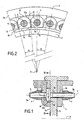
- the Figures 1 and 2 show the fastening system of three parts substantially of revolution about an axis X, which can be for example, a flange 2 of a turbine wheel, a flange 3 of a support bearing, and a flange 4 carrying a labyrinth sealing device.
- This system consists of a plurality of pins 5 whose ends 5a and 5b are threaded to receive clamping nuts 6 and 7 and which have in their central zone a flange 8.
- the studs 5 are regularly distributed around the X axis and through holes 9a, 9b and 9c formed respectively in correspondence in parts 2, 3 and 4.
- the Y axes of the studs 5 are parallel to the axis X.
- the bearing surfaces of the parts 2, 3 and 4 are parallel to each other and extend in planes perpendicular to the X axis.
- the piece 2 has on its face 2a bearing against the face 3a of the piece 3, an annular groove 10 for housing the flanges 8 of the studs 5.
- This groove 10 has a U-shaped section in a radial plane containing the axis X and is delimited by a bottom 11 perpendicular to the axis X, and two cylindrical walls 12a and 12b of axis X and spaced radially by a distance d.
- the holes 9a open into the bottom 11 substantially midway between the cylindrical walls 12a and 12b.
- the contour of the flanges 8 is defined in such a way that, during the tightening of any one of the tightening nuts 6, 7, the flanges can not bear against the cylindrical walls 12a and 12b, but block each other to ensure anti-rotation of the studs 5.
- each flange 8 has four faces, namely a radially inner face 14 and a radially outer face 15, substantially cylindrical and spaced by a distance d1 less than the width d of the groove 10, and two flat lateral faces 16 and 17 which form between them an angle A substantially equal to the angular distance B between two adjacent holes 9a, as is shown in FIG. figure 2 .
- the studs 5 are first fixed on the piece 2, placing the flanges 8 side by side in the groove 10.
- the flat face 16 of a flange 8 and the face 17 of the adjacent flange are thus in the same radial plane containing the axis X, then proceeds to the establishment and tightening of the nuts 6.
- the adjacent flat faces 16 and 17 of two adjacent studs thus come to bear one against the other and immobilize in rotation the studs 5, after a slight rotation of the collars 8 (as shown in FIG. figure 4 ) related to the game between two studs.
- This flat support between the studs, by their faces 16, 17 allows a good distribution of stresses, which increases the lifetime of the studs.
- the parts 3 and 4 are then mounted on the ends of the studs 5 which emerge on the face 2a of the part 2 and the nuts 7 are put in place and tightened.
Landscapes
- Engineering & Computer Science (AREA)
- General Engineering & Computer Science (AREA)
- Mechanical Engineering (AREA)
- Connection Of Plates (AREA)
- Turbine Rotor Nozzle Sealing (AREA)
Claims (6)
- System zur Befestigung von wenigstens zwei Teilen, von denen das eine (2, 3) wenigstens einen in Anlage an einer Fläche des anderen Teils befindlichen Flansch aufweist, mit Hilfe einer Vielzahl von Bolzen (5), wobei ein solcher Bolzen zwei mit Gewinde versehene Enden umfaßt und in seinem mittleren Bereich einen Kragen (8) mit nicht kreisförmiger Kontur aufweist, der in einer Nut (10) aufgenommen ist, welche in einer Anlagefläche (2a) von einem (2) der Teile ausgebildet ist, wobei die Kragen dazu bestimmt sind, die Verdrehsicherung der Bolzen (5) sicherzustellen, dadurch gekennzeichnet, daß die Kontur eines jeden Kragens (8) zwei im wesentlichen einander gegenüberliegende plane Flächen (16, 17) aufweist, die als gegenseitiger Anschlag dienen, der die Verdrehsicherung der benachbarten Bolzen gegenüber den Kragen sicherstellt.
- System nach Anspruch 1, dadurch gekennzeichnet, daß die beiden Teile (2, 3) im wesentlichen rotationssymmetrisch um eine Achse (X) sind und daß die Anlageflächen senkrecht zu der Achse (X) verlaufen.
- System nach Anspruch 2, dadurch gekennzeichnet, daß die planen Flächen (16, 17) der Kragen in die Achse (X) enthaltenden Ebenen erstrecken.
- System nach Anspruch 3, dadurch gekennzeichnet, daß der durch die Ebenen gebildete Winkel (A) im wesentlichen gleich dem Winkelabstand (B) zwischen zwei benachbarten Bolzen (5) ist.
- System nach einem der Ansprüche 1 bis 4, dadurch gekennzeichnet, daß das eine der Teile ein Turbinenrad und das andere Teil ein Flansch ist.
- System nach Anspruch 1, dadurch gekennzeichnet, daß die planen Flächen (16, 17) von zwei benachbarten Bolzen in Plananlage aneinander liegen.
Applications Claiming Priority (2)
| Application Number | Priority Date | Filing Date | Title |
|---|---|---|---|
| FR0404313 | 2004-04-23 | ||
| FR0404313A FR2869374B1 (fr) | 2004-04-23 | 2004-04-23 | Systeme de fixation de pieces par des goujons a collerettes |
Publications (2)
| Publication Number | Publication Date |
|---|---|
| EP1589189A1 EP1589189A1 (de) | 2005-10-26 |
| EP1589189B1 true EP1589189B1 (de) | 2009-09-02 |
Family
ID=34942189
Family Applications (1)
| Application Number | Title | Priority Date | Filing Date |
|---|---|---|---|
| EP05290893A Expired - Lifetime EP1589189B1 (de) | 2004-04-23 | 2005-04-22 | Befestigungssystem für Gewindestiftverbindungen mit Auskragung |
Country Status (8)
| Country | Link |
|---|---|
| US (1) | US7766574B2 (de) |
| EP (1) | EP1589189B1 (de) |
| JP (1) | JP4948780B2 (de) |
| CA (1) | CA2503657C (de) |
| DE (1) | DE602005016333D1 (de) |
| ES (1) | ES2332919T3 (de) |
| FR (1) | FR2869374B1 (de) |
| RU (1) | RU2360153C2 (de) |
Families Citing this family (18)
| Publication number | Priority date | Publication date | Assignee | Title |
|---|---|---|---|---|
| FR2920492B1 (fr) * | 2007-08-30 | 2009-10-30 | Snecma Sa | Etage d'aubes a calage variable pour une turbomachine |
| FR2922588B1 (fr) * | 2007-10-22 | 2013-11-01 | Snecma | Disque ou tambour de rotor d'une turbomachine |
| FR2933887B1 (fr) * | 2008-07-18 | 2010-09-17 | Snecma | Procede de reparation ou de reprise d'un disque de turbomachine et disque de turbomachine repare ou repris |
| GB201111666D0 (en) * | 2011-07-08 | 2011-08-24 | Rolls Royce Plc | A joint assembly for an annular structure |
| FR2982907B1 (fr) * | 2011-11-23 | 2013-12-27 | Snecma | Systeme mecanique pour turbomachine, turbomachine et procede de fixation d'un systeme mecanique dans une turbomachine |
| RU2506427C1 (ru) * | 2012-11-07 | 2014-02-10 | Российская Федерация, от имени которой выступает Министерство промышленности и торговли Российской Федерации (Минпромторг России) | Ротор турбины газотурбинного двигателя |
| FR3001515B1 (fr) * | 2013-01-25 | 2015-03-20 | Snecma | Assemblage de masselotte d'equilibrage a un element de rotor |
| US9328764B2 (en) * | 2013-07-01 | 2016-05-03 | Hamilton Sundstrand Corporation | Fastening system including removable stud and retaining plate |
| JP6096639B2 (ja) * | 2013-10-29 | 2017-03-15 | 三菱日立パワーシステムズ株式会社 | 回転機械 |
| DE102014222060A1 (de) * | 2014-10-29 | 2016-05-04 | Siemens Aktiengesellschaft | Schraubenbolzen, Gehäuse für eine Turbine, Turbine sowie Verfahren zur Montage eines Gehäuses einer Turbine |
| US10344675B2 (en) | 2016-05-26 | 2019-07-09 | Rolls-Royce Corporation | Fastener and method of restricting fluid flow using same |
| US10385874B2 (en) * | 2017-05-08 | 2019-08-20 | Solar Turbines Incorporated | Pin to reduce relative rotational movement of disk and spacer of turbine engine |
| US10577976B2 (en) * | 2017-10-30 | 2020-03-03 | United Technologies Corporation | Mounting assembly with rotatable and/or translatable retainer pins |
| CN111485955A (zh) * | 2020-04-16 | 2020-08-04 | 中国航发沈阳发动机研究所 | 一种转子轮盘装配结构 |
| FR3118790B1 (fr) * | 2021-01-14 | 2024-09-06 | Safran Aircraft Engines | Module de turbomachine comportant des plaques de verrouillage mutuel. |
| FR3139594B1 (fr) * | 2022-09-13 | 2024-08-09 | Safran Aircraft Engines | Jeu d’éléments de fixation autobloquants et ensemble de rotor de turbomachine équipé d’un tel jeu. |
| FR3140648B1 (fr) * | 2022-10-05 | 2025-10-10 | Safran Aircraft Engines | Procédé de fixation d’au moins deux brides de disques de turbine |
| EP4575190A3 (de) * | 2023-12-22 | 2025-10-29 | Rohr, Inc. | Befestigungsanordnung für einen gasturbinenmotormittelkörper und verfahren zur befestigung eines mittelkörpers |
Family Cites Families (20)
| Publication number | Priority date | Publication date | Assignee | Title |
|---|---|---|---|---|
| US2525217A (en) * | 1949-07-06 | 1950-10-10 | Glitsch Engineering Company | Manway clamp |
| BE507205A (de) * | 1950-12-08 | |||
| US3371644A (en) * | 1966-10-13 | 1968-03-05 | Oscar A. Yost | Propeller drive shaft and bearing assembly |
| US3739451A (en) * | 1972-09-29 | 1973-06-19 | R Jacobson | Multiple-bolt installation jig |
| FR2367943A1 (fr) * | 1976-10-15 | 1978-05-12 | Europ Turb Vapeur | Dispositif de liaison entre deux rotors |
| US4190397A (en) * | 1977-11-23 | 1980-02-26 | General Electric Company | Windage shield |
| US4245959A (en) * | 1978-11-13 | 1981-01-20 | General Electric Company | Windage nut |
| JPS61157815A (ja) * | 1984-12-27 | 1986-07-17 | 川崎重工業株式会社 | 両ねじボルト |
| US4747750A (en) * | 1986-01-17 | 1988-05-31 | United Technologies Corporation | Transition duct seal |
| FR2607866B1 (fr) * | 1986-12-03 | 1991-04-12 | Snecma | Axes de fixation de rotors de turbomachine, procede de montage et rotors ainsi montes |
| DE3641290C1 (de) * | 1986-12-03 | 1988-05-11 | Messerschmitt Boelkow Blohm | Modul- und Montagesystem |
| DE3924829A1 (de) * | 1989-07-27 | 1991-02-07 | Mtu Muenchen Gmbh | Verdichter-oder turbinenlaeufer, insbesondere fuer gasturbinentriebwerke |
| US5215335A (en) * | 1991-08-26 | 1993-06-01 | Air-Way Manufacturing Company | Fitting for pressurized fluid lines and method for making same |
| US5226788A (en) * | 1991-12-23 | 1993-07-13 | General Electric Company | Turbine heat shield and bolt retainer assembly |
| US5211541A (en) * | 1991-12-23 | 1993-05-18 | General Electric Company | Turbine support assembly including turbine heat shield and bolt retainer assembly |
| GB2303188B (en) * | 1995-07-13 | 1999-04-28 | Bmw Rolls Royce Gmbh | An assembly of two turbine rotor discs |
| RU2140023C1 (ru) * | 1998-06-10 | 1999-10-20 | Открытое акционерное общество Научно-производственное объединение "Искра" | Стык рамных конструкций |
| US6231287B1 (en) * | 2000-02-28 | 2001-05-15 | General Electric Co. | Rotor windage nut |
| US6641326B2 (en) * | 2001-12-21 | 2003-11-04 | General Electric Company | Removable stud for joining casing flanges |
| US6887043B2 (en) | 2003-03-28 | 2005-05-03 | General Electric Company | Methods and apparatus for assembling gas turbine engines |
-
2004
- 2004-04-23 FR FR0404313A patent/FR2869374B1/fr not_active Expired - Fee Related
-
2005
- 2005-04-18 US US11/107,854 patent/US7766574B2/en not_active Expired - Lifetime
- 2005-04-21 JP JP2005123378A patent/JP4948780B2/ja not_active Expired - Lifetime
- 2005-04-21 CA CA2503657A patent/CA2503657C/fr not_active Expired - Lifetime
- 2005-04-22 RU RU2005112102/11A patent/RU2360153C2/ru active
- 2005-04-22 EP EP05290893A patent/EP1589189B1/de not_active Expired - Lifetime
- 2005-04-22 ES ES05290893T patent/ES2332919T3/es not_active Expired - Lifetime
- 2005-04-22 DE DE602005016333T patent/DE602005016333D1/de not_active Expired - Lifetime
Also Published As
| Publication number | Publication date |
|---|---|
| US20050238423A1 (en) | 2005-10-27 |
| ES2332919T3 (es) | 2010-02-15 |
| EP1589189A1 (de) | 2005-10-26 |
| JP2005308223A (ja) | 2005-11-04 |
| FR2869374B1 (fr) | 2009-01-30 |
| CA2503657A1 (fr) | 2005-10-23 |
| CA2503657C (fr) | 2011-09-20 |
| JP4948780B2 (ja) | 2012-06-06 |
| DE602005016333D1 (de) | 2009-10-15 |
| FR2869374A1 (fr) | 2005-10-28 |
| US7766574B2 (en) | 2010-08-03 |
| RU2360153C2 (ru) | 2009-06-27 |
| RU2005112102A (ru) | 2006-10-27 |
Similar Documents
| Publication | Publication Date | Title |
|---|---|---|
| EP1589189B1 (de) | Befestigungssystem für Gewindestiftverbindungen mit Auskragung | |
| EP1717415B1 (de) | Turbinenmodul für einen Gasturbinentriebwerk | |
| EP1584785B1 (de) | Kompensationsmasse zur Auswuchtung eines Rotors für einen Rotor eines Flugtriebwerks | |
| EP1606860B1 (de) | Elektrisches und mechanisches verbindungssystem mindestens eines leiters in form einer platte auf einem träger | |
| EP3325827B1 (de) | Anordnung mit verriegeltem sicherungsbolzen | |
| EP3306164B1 (de) | Spannsystem in kontrollierter winkelposition für anschluss von zwei rohren | |
| FR2618870A1 (fr) | Collier de serrage pour le raccordement de deux tubes metalliques | |
| FR3090052A1 (fr) | Assemblage à pièces vissées auto-freinantes | |
| WO2013076417A1 (fr) | Systeme mecanique pour turbomachine, turbomachine et procede de fixation d'un systeme mecanique dans une turbomachine | |
| EP1491778B1 (de) | Befestigungsvorrichtung durch Schrauben und Muttern | |
| FR3082874A1 (fr) | Piece annulaire de fonderie et frettee d'une turbomachine d'aeronef | |
| EP2060751B1 (de) | Turbinen- oder Kompressorstufe eines Turbotriebwerks | |
| CA3066174A1 (fr) | Fixation a verrouillage positif | |
| EP3074596B1 (de) | Ausgewuchtetes gasturbinenmotorteil und zugehöriges verfahren | |
| EP1223309B1 (de) | Doppelte Schaufelblatthalterung | |
| EP2427658B1 (de) | Lüfterrotor für ein mantelstrom-triebwerk eines flugzeuges | |
| EP2060744B1 (de) | Turbinen- oder Kompressorstufe eines Turbotriebwerks | |
| FR3051014A1 (fr) | Ensemble pour turbomachine comprenant un distributeur, un element de structure de turbomachine, et un dispositif de fixation | |
| EP3969663B1 (de) | Passierbare dehnungsfuge | |
| EP4229280B1 (de) | Turbomaschinenmodul mit platten zum verriegeln von laschenpaaren | |
| EP4519127B1 (de) | Vorrichtung zum reinigen einer optischen oberfläche eines optischen sensors eines fahrzeugs und detektionssystem | |
| FR3139855A1 (fr) | Ensemble rotatif de turbomachine comprenant un dispositif de retenue axiale de pieds d’aube dans les alvéoles d’un disque de rotor | |
| FR3033175B1 (fr) | Escalier a vis | |
| FR3151064A1 (fr) | Rondelle de blocage robuste à déblocage rapide et système de fixation pourvu d’une telle rondelle de blocage. | |
| FR3049318A1 (fr) | Systeme de bouchage pour bague de roulement |
Legal Events
| Date | Code | Title | Description |
|---|---|---|---|
| PUAI | Public reference made under article 153(3) epc to a published international application that has entered the european phase |
Free format text: ORIGINAL CODE: 0009012 |
|
| 17P | Request for examination filed |
Effective date: 20050503 |
|
| AK | Designated contracting states |
Kind code of ref document: A1 Designated state(s): AT BE BG CH CY CZ DE DK EE ES FI FR GB GR HU IE IS IT LI LT LU MC NL PL PT RO SE SI SK TR |
|
| AX | Request for extension of the european patent |
Extension state: AL BA HR LV MK YU |
|
| AKX | Designation fees paid |
Designated state(s): DE ES FR GB IT SE |
|
| 17Q | First examination report despatched |
Effective date: 20081107 |
|
| GRAP | Despatch of communication of intention to grant a patent |
Free format text: ORIGINAL CODE: EPIDOSNIGR1 |
|
| GRAC | Information related to communication of intention to grant a patent modified |
Free format text: ORIGINAL CODE: EPIDOSCIGR1 |
|
| GRAS | Grant fee paid |
Free format text: ORIGINAL CODE: EPIDOSNIGR3 |
|
| GRAA | (expected) grant |
Free format text: ORIGINAL CODE: 0009210 |
|
| AK | Designated contracting states |
Kind code of ref document: B1 Designated state(s): DE ES FR GB IT SE |
|
| REF | Corresponds to: |
Ref document number: 602005016333 Country of ref document: DE Date of ref document: 20091015 Kind code of ref document: P |
|
| REG | Reference to a national code |
Ref country code: SE Ref legal event code: TRGR |
|
| REG | Reference to a national code |
Ref country code: ES Ref legal event code: FG2A Ref document number: 2332919 Country of ref document: ES Kind code of ref document: T3 |
|
| PLBE | No opposition filed within time limit |
Free format text: ORIGINAL CODE: 0009261 |
|
| STAA | Information on the status of an ep patent application or granted ep patent |
Free format text: STATUS: NO OPPOSITION FILED WITHIN TIME LIMIT |
|
| 26N | No opposition filed |
Effective date: 20100603 |
|
| PGFP | Annual fee paid to national office [announced via postgrant information from national office to epo] |
Ref country code: ES Payment date: 20120410 Year of fee payment: 8 |
|
| REG | Reference to a national code |
Ref country code: ES Ref legal event code: FD2A Effective date: 20140606 |
|
| PG25 | Lapsed in a contracting state [announced via postgrant information from national office to epo] |
Ref country code: ES Free format text: LAPSE BECAUSE OF NON-PAYMENT OF DUE FEES Effective date: 20130423 |
|
| REG | Reference to a national code |
Ref country code: FR Ref legal event code: PLFP Year of fee payment: 12 |
|
| REG | Reference to a national code |
Ref country code: FR Ref legal event code: PLFP Year of fee payment: 13 |
|
| REG | Reference to a national code |
Ref country code: FR Ref legal event code: CD Owner name: SAFRAN AIRCRAFT ENGINES, FR Effective date: 20170719 |
|
| REG | Reference to a national code |
Ref country code: FR Ref legal event code: PLFP Year of fee payment: 14 |
|
| PGFP | Annual fee paid to national office [announced via postgrant information from national office to epo] |
Ref country code: GB Payment date: 20240320 Year of fee payment: 20 |
|
| PGFP | Annual fee paid to national office [announced via postgrant information from national office to epo] |
Ref country code: SE Payment date: 20240320 Year of fee payment: 20 Ref country code: IT Payment date: 20240320 Year of fee payment: 20 Ref country code: FR Payment date: 20240320 Year of fee payment: 20 |
|
| PGFP | Annual fee paid to national office [announced via postgrant information from national office to epo] |
Ref country code: DE Payment date: 20240320 Year of fee payment: 20 |
|
| REG | Reference to a national code |
Ref country code: DE Ref legal event code: R071 Ref document number: 602005016333 Country of ref document: DE |
|
| REG | Reference to a national code |
Ref country code: GB Ref legal event code: PE20 Expiry date: 20250421 |
|
| REG | Reference to a national code |
Ref country code: SE Ref legal event code: EUG |
|
| PG25 | Lapsed in a contracting state [announced via postgrant information from national office to epo] |
Ref country code: GB Free format text: LAPSE BECAUSE OF EXPIRATION OF PROTECTION Effective date: 20250421 |