EP1588733B1 - Punktionsballon mit endoskop - Google Patents
Punktionsballon mit endoskop Download PDFInfo
- Publication number
- EP1588733B1 EP1588733B1 EP04706835A EP04706835A EP1588733B1 EP 1588733 B1 EP1588733 B1 EP 1588733B1 EP 04706835 A EP04706835 A EP 04706835A EP 04706835 A EP04706835 A EP 04706835A EP 1588733 B1 EP1588733 B1 EP 1588733B1
- Authority
- EP
- European Patent Office
- Prior art keywords
- balloon
- endoscope
- extreme end
- puncture
- mpa
- Prior art date
- Legal status (The legal status is an assumption and is not a legal conclusion. Google has not performed a legal analysis and makes no representation as to the accuracy of the status listed.)
- Expired - Fee Related
Links
Images


Classifications
-
- A—HUMAN NECESSITIES
- A61—MEDICAL OR VETERINARY SCIENCE; HYGIENE
- A61M—DEVICES FOR INTRODUCING MEDIA INTO, OR ONTO, THE BODY; DEVICES FOR TRANSDUCING BODY MEDIA OR FOR TAKING MEDIA FROM THE BODY; DEVICES FOR PRODUCING OR ENDING SLEEP OR STUPOR
- A61M25/00—Catheters; Hollow probes
- A61M25/10—Balloon catheters
-
- A—HUMAN NECESSITIES
- A61—MEDICAL OR VETERINARY SCIENCE; HYGIENE
- A61B—DIAGNOSIS; SURGERY; IDENTIFICATION
- A61B17/00—Surgical instruments, devices or methods, e.g. tourniquets
- A61B17/34—Trocars; Puncturing needles
- A61B17/3403—Needle locating or guiding means
-
- A—HUMAN NECESSITIES
- A61—MEDICAL OR VETERINARY SCIENCE; HYGIENE
- A61B—DIAGNOSIS; SURGERY; IDENTIFICATION
- A61B17/00—Surgical instruments, devices or methods, e.g. tourniquets
- A61B17/34—Trocars; Puncturing needles
- A61B17/3417—Details of tips or shafts, e.g. grooves, expandable, bendable; Multiple coaxial sliding cannulas, e.g. for dilating
- A61B17/3421—Cannulas
-
- A—HUMAN NECESSITIES
- A61—MEDICAL OR VETERINARY SCIENCE; HYGIENE
- A61B—DIAGNOSIS; SURGERY; IDENTIFICATION
- A61B90/00—Instruments, implements or accessories specially adapted for surgery or diagnosis and not covered by any of the groups A61B1/00 - A61B50/00, e.g. for luxation treatment or for protecting wound edges
- A61B90/39—Markers, e.g. radio-opaque or breast lesions markers
-
- A—HUMAN NECESSITIES
- A61—MEDICAL OR VETERINARY SCIENCE; HYGIENE
- A61B—DIAGNOSIS; SURGERY; IDENTIFICATION
- A61B17/00—Surgical instruments, devices or methods, e.g. tourniquets
- A61B17/34—Trocars; Puncturing needles
- A61B17/3494—Trocars; Puncturing needles with safety means for protection against accidental cutting or pricking, e.g. limiting insertion depth, pressure sensors
-
- A—HUMAN NECESSITIES
- A61—MEDICAL OR VETERINARY SCIENCE; HYGIENE
- A61B—DIAGNOSIS; SURGERY; IDENTIFICATION
- A61B17/00—Surgical instruments, devices or methods, e.g. tourniquets
- A61B17/00234—Surgical instruments, devices or methods, e.g. tourniquets for minimally invasive surgery
- A61B2017/00292—Surgical instruments, devices or methods, e.g. tourniquets for minimally invasive surgery mounted on or guided by flexible, e.g. catheter-like, means
-
- A—HUMAN NECESSITIES
- A61—MEDICAL OR VETERINARY SCIENCE; HYGIENE
- A61B—DIAGNOSIS; SURGERY; IDENTIFICATION
- A61B17/00—Surgical instruments, devices or methods, e.g. tourniquets
- A61B17/22—Implements for squeezing-off ulcers or the like on the inside of inner organs of the body; Implements for scraping-out cavities of body organs, e.g. bones; Calculus removers; Calculus smashing apparatus; Apparatus for removing obstructions in blood vessels, not otherwise provided for
- A61B2017/22051—Implements for squeezing-off ulcers or the like on the inside of inner organs of the body; Implements for scraping-out cavities of body organs, e.g. bones; Calculus removers; Calculus smashing apparatus; Apparatus for removing obstructions in blood vessels, not otherwise provided for with an inflatable part, e.g. balloon, for positioning, blocking, or immobilisation
- A61B2017/22065—Functions of balloons
- A61B2017/22068—Centering
-
- A—HUMAN NECESSITIES
- A61—MEDICAL OR VETERINARY SCIENCE; HYGIENE
- A61B—DIAGNOSIS; SURGERY; IDENTIFICATION
- A61B17/00—Surgical instruments, devices or methods, e.g. tourniquets
- A61B17/22—Implements for squeezing-off ulcers or the like on the inside of inner organs of the body; Implements for scraping-out cavities of body organs, e.g. bones; Calculus removers; Calculus smashing apparatus; Apparatus for removing obstructions in blood vessels, not otherwise provided for
- A61B2017/22051—Implements for squeezing-off ulcers or the like on the inside of inner organs of the body; Implements for scraping-out cavities of body organs, e.g. bones; Calculus removers; Calculus smashing apparatus; Apparatus for removing obstructions in blood vessels, not otherwise provided for with an inflatable part, e.g. balloon, for positioning, blocking, or immobilisation
- A61B2017/22065—Functions of balloons
- A61B2017/22069—Immobilising; Stabilising
-
- A—HUMAN NECESSITIES
- A61—MEDICAL OR VETERINARY SCIENCE; HYGIENE
- A61B—DIAGNOSIS; SURGERY; IDENTIFICATION
- A61B17/00—Surgical instruments, devices or methods, e.g. tourniquets
- A61B17/34—Trocars; Puncturing needles
- A61B2017/348—Means for supporting the trocar against the body or retaining the trocar inside the body
- A61B2017/3482—Means for supporting the trocar against the body or retaining the trocar inside the body inside
- A61B2017/3484—Anchoring means, e.g. spreading-out umbrella-like structure
- A61B2017/3486—Balloon
-
- A—HUMAN NECESSITIES
- A61—MEDICAL OR VETERINARY SCIENCE; HYGIENE
- A61B—DIAGNOSIS; SURGERY; IDENTIFICATION
- A61B90/00—Instruments, implements or accessories specially adapted for surgery or diagnosis and not covered by any of the groups A61B1/00 - A61B50/00, e.g. for luxation treatment or for protecting wound edges
- A61B90/39—Markers, e.g. radio-opaque or breast lesions markers
- A61B2090/3925—Markers, e.g. radio-opaque or breast lesions markers ultrasonic
Definitions
- the present invention relates to a tool for safely and reliably securing a route for endermically approaching the interior of the body, and more specifically, to a puncture balloon that is designed to allow a balloon that does not immediately burst when punctured by a puncturing needle or the like to be used as a target, and that can be used by installing or inserting an endoscope in a tube holding such balloon.
- PEG percutaneous endoscopic gastrostomy
- Nakano et al developed a method of forming a cervical esophagus fistula under the X-ray clairvoyance in 1993.
- An indwelling method is such that a tube with a balloon is nasogastrically inserted in the esophagus, barium meal is injected into the balloon in the cervical esophagus, and the lumen of the cervical esophagus is expanded. Then, the cervical esophagus is endermically punctured under the X-ray clairvoyance to thereby form a cervical esophagus fistula, and a nutrition tube is indwelled therein.
- the indwelling method is simple, a patient is less invaded and pained, and the forming method is effective to a long-term nutrition management.
- puncturing is executed only under the X-ray clairvoyance, there is a possibility of danger from the viewpoint of the anatomical structure of the neck.
- the tube with the balloon uses a Foley catheter, whether or not a puncturing needle reaches the lumen of the esophagus when punctured is determined by that the balloon bursts.
- the wall of the esophagus may be damaged by the extreme end of the needle after the balloon bursts and that since the puncturing needle is punctured shallow, it may be removed from the wall of the esophagus.
- Ohishi et al who are the inventors of the present invention, improved the method of forming the cervical esophagus fistula under the X-ray clairvoyance of Nakano et al and devised a method of safely and reliably puncturing the balloon of a balloon catheter by a puncturing needle while confirming the position of the balloon from the outside of the body using an ultrasonic probe (refer to, for example, non-patent documents 1 and 2).
- this method also employs a Foley catheter likewise Nakano et al and still has a worry in that the wall of the esophagus may be damaged by the extreme end of a puncturing needle after the balloon bursts and that the needle may be removed from the wall of the esophagus.
- the inventors of the present invention further improved the method of forming the cervical esophagus fistula and intended to form the cervical esophagus fistula at a bedside by composing the balloon of a balloon catheter to be punctured of a balloon which does not burst even it is punctured and combining the balloon with a dedicated introduction tool (refer to, for example, patent document 2) without using an X-ray apparatus and an endoscope.
- a dedicated introduction tool reference to, for example, patent document 2
- JP 09 117454 A describes a kit for safe and secure cure for the stomach originating in liver disease and an esophageal varix.
- the kit has an installation member having a cylindrical device fixed on the top end of an endoscope for fixing a ligature kit for pulling in varicosis on a stomach or esophagus, etc., and for knotting it with an O-ring and a balloon part.
- An air duct tube for expanding a cuff is disposed on the rear end of the cuff and an air tight closing apparatus is disposed on the near end of the air duct tube communicated to the balloon part.
- the balloon part comprises an inside layer directly being in contact with the endoscope and an outside layer to be expanded as a balloon.
- the ligature kit has a sliding cylinder between the inside cylinder and the outside cylinder, and an air driving system for thrusting a sliding cylinder out by pressing a fluid therein and thereby for dropping the O ring out.
- An object of the present invention which was made in view of the above circumstances, is to provide a tool for safely and reliably securing a route for endermically approaching the interior of the body, and more specifically, toprovideanendoscope-equipped puncture balloon that is designed to allow a balloon that does not immediately burst when punctured by a puncturing needle or the like to be used as a target, and that can be used by installing or inserting an endoscope in a tube holding such balloon.
- a first invention is arranged as described below.
- Endermic routes for various purposes can be made safely and reliably to all the duct cavities and the internal organs (esophagus, stomach, bile duct, pancreatic duct, bowel, urinary duct, bladder, and the like) using the puncture balloon of the present invention equipped with the endoscope.
- Fig. 1 is a side sectional view of an endoscope-equipped puncture balloon as a first embodiment of a first invention
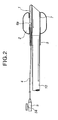
- Fig. 2 is a side sectional view of the endoscope-equipped puncture balloon of Fig. 1 that uses another example as the main body tube thereof
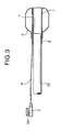
- Fig. 3 is a side sectional view of an endoscope-equipped puncture balloon as another example of the first invention
- Fig. 4 is a schematic view showing an example of a method of using the puncture balloons of Figs. 1 to 3
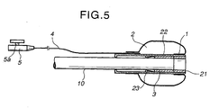
- FIG. 5 is a side sectional view of an example of an endoscope-equipped puncture balloon as a first embodiment of a second invention in which a balloon is disposed at a retreat position
- Fig. 6 is a side sectional view of the endoscope-equipped puncture balloon of Fig. 5
- Fig. 7 is a schematic view showing an example in which the puncture balloon of the second invention exemplified in Fig. 6 is inserted into an esophagus inlet
- Fig. 8 is a schematic view showing a state in which an endoscope is pulled while expanding the puncture balloon inserted beyond the esophagus inlet in Fig. 7
- FIG. 9 is a schematic view showing a state in which a puncture needle is punctured into the puncture balloon of Fig. 8
- Fig. 10 is a side sectional view of a puncture balloon as a first embodiment of a third invention
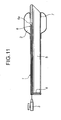
- Fig. 11 is a side sectional view showing another example of an overtube of the puncture balloon of Fig. 10
- Fig. 12 is a schematic view explaining how the puncture balloon having the endoscope insertion overtube of Fig. 11 is used.
- the puncture balloon of the first invention is composed of a main body tube 1, a balloon 2, an endoscope-installed section 3, a branch tube 4, and a connector 5.
- the main body tube 1 of Fig. 1 is a thin-walled main body tube and has one or more lumens, and one of the lumens is a balloon expansion lumen 6 which has a closed extreme end and a side hole 6a that opens in the lumen of the balloon.
- the main body tube 1 be formed in a diameter approximately the same as that of an endoscope 10 to be used according to the constitution of a patient and an insert position, it is preferable that the main body tube 1 have a projecting length of 50 mm or less from the extreme end of the endoscope so that the inserting property thereof is not deteriorated by that the length from angle section of the endoscope at the extreme end thereof is made too long, and it is more preferable that the main body tube 1 have the projecting length of 30 mm or less together with the length of the balloon.
- the main body tube 1 has appropriate flexibility and elasticity due to ordinary room and body temperatures, and synthetic resin, for example, soft vinyl chloride resin, polyurethane resin, silicone rubber, or the like is ordinarily preferably used as a material for forming the main body tube 1.
- synthetic resin for example, soft vinyl chloride resin, polyurethane resin, silicone rubber, or the like is ordinarily preferably used as a material for forming the main body tube 1.
- the material of the main body tube 1 is by no means limited thereto, and it is preferable that the material used to the main body tube 1 have such a degree of transparency as to allow the interior of the balloon to be visually recognized through the endoscope.
- the branch tube 4 to be described later may be directly disposed in the balloon 2 to be installed as shown in Fig. 3 . It is preferable to install the branch tube 4 as exemplified in Fig. 3 because this is advantageous in that the main body tube 1 has improved flexibility, no directionality, and the like.
- the extreme end of the main body tube 1 is subjected to chamfering and the like to improve the insertion property thereof, and further it is preferable to cut the extreme end of the tube obliquely in place of cutting it at right angles to improve the insertion property thereof refer to Fig.2 .
- the balloon 2 is formed to a length of 1 - 20 cm, an expanded diameter of 5 - 200 mm, and a wall thickness of 0.01-1mm depending on a section into which it is inserted.
- the wall thickness thereof is set to, for example, 0.1 - 0.3 mm to prevent it from being made bulky as much as possible.
- the length thereof is approximately 3 - 10 cm, and the expanded diameter thereof is set to approximately 30 mm, and when the balloon 2 is used to the stomach, the length thereof is set to approximately 5 - 20 cm, and the expanded diameter thereof is set to approximately 200 mm.
- selected as a material for forming the balloon 2 is ordinarily synthetic resin having hardness of JIS SA 20 - 80°, tensile strength of 8 - 25 MPa, tearing strength of 20 - 60 kg/cm, 100% modulus of 3 - 6 MPa, elongation of 300 - 460%, and balloon inside pressure of 19.3 MPa-517,106 MPa (2.8 - 75 psi).
- soft vinyl chloride resin, polyurethane resin, silicone rubber, or the like for example, are preferably used, the material is by no means limited thereto, and polyethylene, polyester, natural rubber latex, and the like may be used.
- the balloon 2 when the balloon 2 is formed using silicone rubber, natural rubber, or the like, there is a possibility that the balloon 2 immediately bursts due to the elasticity thereof when punched by a puncturing needle. Accordingly, the balloon 2 may be impregnated or laminated with nylon meshes and the like so that it does not immediately burst even if punctured by the puncturing needle.
- the balloon 2 to be orally inserted into the esophagus is formed of soft vinyl chloride resin
- a material having hardness of approximately 60°, tensile strength of approximately 16 MPa, tear strength of approximately 45 kg/cm, 100% modulus of approximately 4.5 MPa, and elongation of approximately 400% is selected, and the wall thickness of the balloon is set to approximately 0.1 - 0.3 mm, and the outside diameter thereof is set to approximately 2/3 the desired expanded diameter thereof.
- a balloon-installed section 7 on the extreme end side of the main body tube 1 be installed by being bent backward so that it is disposed inside of the balloon 2, and a means such as bonding, welding, or the like is selected to install the balloon 2.
- the rear end of the main body tube 1 itself may be used as the endoscope-installed section 3 as long as the mounting/dismounting operationality of the rear end to the endoscope 10 can be satisfied by the material selected to the main body tube 1.
- the branch tube 4 is used to couple the balloon 2 with the connector 5 to be described later in a gas-liquid flow manner and causes a liquid to flow to expand and contract the balloon 2.
- a material to be used to the branch tube 4 is not particularly limited as long as it has flexibility and sufficient strength, and soft vinyl chloride resin, polyurethane resin, silicone rubber, or the like are preferably used.
- the connector 5 must be formed to have a lure taper so that it is connected to a syringe to inject a balloon expanding liquid and a liquid medicine.
- a valve member 5a one-way valve, two-way turncock, three-way turncock, and the like
- a connector having a lock type end may be used in some cases.
- the materials of the connector 5 and the valve member 5a are not particularly limited, synthetic resin such as soft vinyl chloride resin, polycarbonate resin, ABS resin, and the like may be preferably used.
- the puncture balloon 2 is orally inserted together with the endoscope-installed section 3 thereof installed to the extreme end of the endoscope 10 used to the upper digestive organ, the bronchial tube, and the other internal organs and tubes, the balloon 2 is expanded at a position beyond an esophagus inlet 13 by physiological saline or the like injected thereinto from the connector 5 to which the syringe 11 and the like is previously connected, further the endoscope 10 is pulled to secure a wide puncture region, and the position of the balloon 2 is confirmed by an ultrasonic probe applied to the cervical region from a body surface.
- the ultrasonic probe is more strongly pressed against the body surface to secure a state in which the thyroid, the throat, the artery, the vein, and the like are offset from the balloon 2, and a puncturing needle 12 is punctured to the balloon 2. It is confirmed by an endoscope image and an ultrasonic image that the balloon 2 neither burst nor contracts at the moment at which the puncturing needle 12 is punctured and that the extreme end of the puncturing needle 12 is reliably located in the interior of the balloon 2.
- a necessary amount of a guide wire (not shown) is inserted from the tail end of the puncturing needle 12, and the puncturing needle 12 is extracted.
- the guide wire is eliminated from the interior of the puncture balloon 2 while being directed toward the stomach while pushing the endoscope 10 and the balloon 2 inward.
- the physiological saline or the like in the balloon 2 is absorbed by the syringe 11, thereby the balloon 2 is contracted and the endoscope 10 is pulled so as to return to the upper region of the esophagus.
- a dilator (not shown) with a sheath is inserted from the tail end of the guide wire while visually recognizing and conforming it also by the endoscope 10 to thereby enlarge the punctured region, and the route to the interior the esophagus is secured by extracting only the dilator. With this operation, a catheter can be appropriately inserted thereafter.
- the region in which the puncture balloon of the present invention is used and the method of using the puncture balloon have been explained above by the method of forming the route for endermically approaching from the cervical region to the interior of the esophagus.
- the puncture balloon of the second invention is obtained by forming the main body tube 1 of the first invention to a two-piece type in which the main body tube 1 is composed of an inner cylinder 21 installed on the extreme end of an endoscope 10 and a slide cylinder 22 to which a balloon 2 is installed.
- the puncture balloon is composed of the inner cylinder 21 having an endoscope-installed section 3, the slide cylinder 22 having the balloon 2 on the surface thereof, a branch tube 4, and a connector 5.
- the inner cylinder 21 is composed of a thin wall molded cylinder and formed to a diameter approximately the same as that of the endoscope 10 according to the constitution of a patient and an insert position. It is preferable that the inner cylinder 21 have a projecting length of 10 mm or less from the extreme end of the endoscope so that the inserting property thereof is not deteriorated by that the length thereof from the curved section of the endoscope at the extreme end thereof is increased.
- the endoscope-installed section 3 which is fitted on and fixed to the extreme end of the endoscope 10, is installed at the rear end of the inner cylinder 21 which is integrated with the endoscope-installed section 3 by a means such as bonding, welding, and the like.
- the inner cylinder 21 having the endoscope-installed section 3 must be transparent and have a thin wall thickness, appropriate mechanical strength, and pinpoint dimensional accuracy so that the slide cylinder 22 to be described later can be fitted on the inner cylinder 21 so as to be free to slide on the inner cylinder 21 forward and backward without resistance (to cover the outside surface of the inner cylinder 21 in the form of a layer) and that the interior of the balloon can be visually recognized. Accordingly, it is preferable that the inner cylinder 21 be molded of resin that satisfies the above conditions.
- Materials to be used in these components are not particularly limited as long as they satisfy the above requirements, and, for example, polycarbonate resin, polyvinyl chloride resin, acrylic resin, ABS resin, polymethylpentene resin, polyamide resin, polyurethane resin, polyester resin, and the polymer alloys thereof are preferably used.
- the endoscope-installed section 3 integrated with the inner cylinder 21 is preferably molded of a material having appropriate flexibility so that it is unlike to separate from the endoscope 10 and does not damage the endoscope 10 by being engaged therewith too tightly on the contrary.
- the material is not particularly limited as long as it satisfies the conditions, and, for example, thermoplastic elastomer and various kinds of rubber are particularly preferably used.
- the slide cylinder 22 is composed of a thin wall molded cylinder and fitted on the inner cylinder 21 so as to be free to slide thereon forward and backward without resistance, and the balloon 2 is disposed on the surface thereof.
- the extreme end position of the slide cylinder 22 is located at the position approximately the same position as the extreme end of the inner cylinder 21 (refer to Fig. 5 ) so that the inserting property of the endoscope is not deteriorated when it is inserted, and it is important that the rear end position of the slide cylinder 22 at the time have a length that does not interfere with the adjustment of the curving of the extreme end of the endoscope.
- a stopper 23 is disposed to the lumen of the slide cylinder 22 to prevent the slide cylinder 22 from moving backward when it is moved forward to the initial moving end thereof (refer to Fig. 6 ).
- the shape of the stopper 23 is not particularly limited, and, for example, a projection may be disposed to the slide cylinder 22 to hook the extreme end of the inner cylinder 21, or a projection may be disposed to the inner cylinder 21 on the contrary, and a groove may be formed to the slide cylinder 22 so that it is engaged with the projection. Note that it is preferable to form the stopper 23 in a shape that minimizes sliding resistance between the inner cylinder 21 and the slide cylinder 22.
- a material which satisfies the same requirements as those of the main body tube 1 described above and is suitable to install the balloon 2 and the branch tube 4, is selected as the material of the slide cylinder 22, and, for example, polycarbonate resin, polyvinyl chloride resin, acrylic resin, ABS resin, polymethylpentene resin, polyamide resin, polyurethane resin, polyester resin, and the polymer alloys thereof are preferably selected.
- the conditions of the balloon 2 in the puncture balloon of the second invention such as the shape, size, wall thickness thereof, the material thereof, and the method of molding it, the method of installing it to the endoscope are the same as those of the example of the first embodiment.
- the branch tube 4 and the connector 5 are also the same as those of the example of the first invention.
- the slide cylinder 22 is designed such that the extreme end side thereof does not extend beyond the curved section of the endoscope at the position where the slide cylinder 22 is moved to the rearmost position thereof when the balloon 2 is inserted into the duct cavity and the internal organ.
- the endoscope 10 is pulled so that the positional relation between the balloon 2 and the extreme end of the endoscope 10 is changed to the positional relation shown in Fig. 6 so that a puncture operation can be visually recognized easily.
- This is to avoid the deterioration of insertion property into the esophagus caused by that the extreme end side of the slide cylinder 22 extends beyond the curved section of the endoscope 10 as well as to previously prevent such a problem as that when the extreme end of the endoscope is covered with the balloon and the slide cylinder, it is difficult to visually recognize the puncture operation and thus the endoscope is punctured and broken.
- the puncture balloon of the second invention when the balloon can be inserted to the predetermined regions of the cavity tube and the internal organ, the endoscope 10 is pulled and returned (refer to Fig. 8 ), thereby the puncture balloon can be punctured without causing any problem (refer to Fig. 9 ).
- the overtube of the puncture balloon is composed of a main body tube 1, a balloon 2, and a connector 4.
- the main body tube 1 is composed of a thin wall tube and has an endoscope insertion lumen 5 and a sub-lumen 6.
- the endoscope insertion lumen 5 has such geometries including an inside diameter and the like and properties that an endoscope 10 can be inserted into and pulled out from the main body tube 1 passing therethrough from the extreme end to the rear end thereof.
- the sub-lumen 6 has a closed extreme end and a side hole 6a opened to the lumen of the balloon 2, and the rear end of the sub-lumen 6 communicates with the connector 4 and injects and evacuates a balloon expanding fluid into and from the lumen of the balloon 2.
- the extreme end of the main body tube 1 is chamfered and cut obliquely likewise the embodiments described previously to improve the insertion property thereof.
- the main body tube 1 is composed of a composite tube and provided with resin or metal meshes embedded therein. The length of the main body tube 1 is set in conformity with a target region.
- the main body tube 1 has appropriate flexibility and elasticity due to ordinary room and body temperatures, and synthetic resin, for example, soft vinyl chloride resin, polyurethane resin, silicone rubber, or the like are ordinarily used preferably as a material for forming the main body tube 1.
- synthetic resin for example, soft vinyl chloride resin, polyurethane resin, silicone rubber, or the like are ordinarily used preferably as a material for forming the main body tube 1.
- the material of the main body tube 1 is by no means limited thereto.
- the outer periphery or the lumen of the main body tube 1 of the present invention be subjected to lubrication processing, and, as examples of the processing, various kinds of hydrogel are practically coated, in addition to coating of fluorine resin and blending of silicone oil to the material thereof, and collagen, polyvinylpyrolidone, polyacrylamide, and the like are preferable as the hydrogel in view of toxicity to human body.
- a method of fixing the hydrogel to the main body tube 1 Utilized as a method of fixing the hydrogel to the main body tube 1 are a method of coating the hydrogel, which is previously made to a solution, to a catheter and then crosslinking it through glutaraldehyde, a method of coating the monomer of the hydrogel and then crosslinking it using a polymerization initiator, a method of coating a hydrogel solution denatured by a photoreactive cross-linking agent to the main body tube 1 and fixing it by light rays irradiated thereto, and the like.
- the main body tube 1 is preferably formed of a material having such a degree of transparency as to allow the interior of the balloon 2 to be visually recognized under an endoscope.
- the specific examples of the length, expanded diameter, wall thickness, and the like of the balloon 2 are the same as those of the examples of the first and second inventions described previously.
- the molding material of the balloon 2 and the physical properties and the mechanical characteristics of the molded balloon 2 as well as the layered structure and the specific example of the specific mode of the balloon 2, the molding method of the balloon 2, and the method of installing the balloon 2 to the main body tube 1, and the like are the same as those of the previous examples.
- the connector 3 to be used is also the same as that of the previous examples.
- the main body tube 1 of the third invention has the endoscope insertion lumen 5 passing therethrough from the extreme end to the rear end thereof to insert and pull out the endoscope into and from the endoscope insertion lumen 5.
- a film-like seal section 4 provided with a slit or a hole may be disposed to the rear end of the endoscope insertion lumen 5 to secure a degree of negative pressure on the extreme end side of the endoscope insertion lumen 5 when the endoscope must be manipulated for suction and the like in treatment.
- the hole or the slit to be installed has a size set slightly smaller than that of the endoscope 10.
- synthetic resin for example, soft vinyl chloride resin, polyurethane resin, silicone rubber, or the like is preferably used as the material of the seal section 4, the material is by no means limited thereto.
- the present invention is arranged as described above, endermic routes for various purposes can be made safely and reliably to all the duct cavities and the internal organs (esophagus, stomach, bile duct, pancreatic duct, bowel, urinary duct, bladder, and the like) using the puncture balloon of the present invention equipped with the endoscope. Further, a procedure, which must be conventionally executed by many persons in an operating room and the like because an X-ray apparatus is used, can be executed by two persons as well as by a bed by combining the endoscope with the ultrasonic probe.
Landscapes
- Health & Medical Sciences (AREA)
- Life Sciences & Earth Sciences (AREA)
- Surgery (AREA)
- Heart & Thoracic Surgery (AREA)
- Animal Behavior & Ethology (AREA)
- General Health & Medical Sciences (AREA)
- Biomedical Technology (AREA)
- Veterinary Medicine (AREA)
- Public Health (AREA)
- Engineering & Computer Science (AREA)
- Molecular Biology (AREA)
- Pathology (AREA)
- Medical Informatics (AREA)
- Nuclear Medicine, Radiotherapy & Molecular Imaging (AREA)
- Oral & Maxillofacial Surgery (AREA)
- Child & Adolescent Psychology (AREA)
- Biophysics (AREA)
- Pulmonology (AREA)
- Anesthesiology (AREA)
- Hematology (AREA)
- Endoscopes (AREA)
- Media Introduction/Drainage Providing Device (AREA)
Claims (12)
- Mit einem Endoskop ausgestatteter Punkturballon, gekennzeichnet durch Umfassen:eines dünnwandigen Hauptkörperschlauchs (1), der an der Vorderfläche seines äußersten Endes einen Ballon (2) angeordnet aufweist und an seinem hinteren Ende einen Abschnitt (3) mit eingebautem Endoskop ausgebildet aufweist, undeines Zweigschlauchs (4), der mit dem Inneren des Ballons (2) in Gas-/Flüssigkeitsströmungsweise kommuniziert und einen Verbinder (5) aufweist, der an seinem hinteren Ende angebaut ist,wobei erst wenn die Flüssigkeit in dem Ballon (2) absorbiert ist, ohne dass der Ballon (2) unmittelbar platzt, wenn er von einer Punktiernadel (12) punktiert wird, eine Bohrung sichergestellt werden kann, bis der Ballon (2) zusammengezogen wird.
- Mit einem Endoskop ausgestatteter Punkturballon nach Anspruch 1, wobei der Ballon (2) eine Wanddicke von 0,01 - 1 mm, eine Zugfestigkeit von 8 - 25 MPa, 100% Modul von 3 = 6 MPa; eine Dehnung von 300 - 460% und einen Balloninnendruck von 19,3 MPa - 517,106 MPa (2,8 - 75 psi) aufweist.
- Mit einem Endoskop ausgestatteter Punkturballon nach Anspruch 1 oder 2, wobei der Hauptkörperschlauch (1) Transparenz zum Ermöglichen des visuellen Erkennens des Inneren des Ballons (2) von dem Endoskop (10) aufweist.
- Mit einem Endoskop ausgestatteter Punkturballon nach einem der Ansprüche 1 - 3, wobei die Länge von dem äußersten Ende des Hauptkörperschlauchs (1) oder von dem äußersten Ende des Ballons (2) zu dem äußersten Ende des Abschnitts (3) mit eingebautem Endoskop 50 mm oder weniger beträgt.
- Mit einem Endoskop ausgestatteter Punkturballon nach einem der Ansprüche 1 - 4, wobei bei Weiten des Ballons (2) der Ballon (2) an der Vorderseite des äußersten Endes des Abschnitts (3) mit eingebautem Endoskop in der Längsrichtung desselben über die gesamte Länge angeordnet ist.
- Mit einem Endoskop ausgestatteter Punkturballon nach einem der Ansprüche 1 - 5, wobei mindestens der Abschnitt (7) mit eingebautem Ballon an der Seite des äußersten Endes des Ballons (2) bezüglich der Längsrichtung des Ballons (2) in dem Ballon (2) angeordnet ist.
- Mit Endoskop ausgestatteter Punkturballon, gekennzeichnet durch Umfassen
eines dünnwandigen Innenzylinders (21), der einen Abschnitt (3) mit eingebautem Endoskop aufweist, der an dem hinteren Ende desselben ausgebildet ist,
eines dünnwandigen Gleitzylinders (22), der an der vorderen Fläche des äußersten Endes desselben einen Ballon (2) angeordnet aufweist, an dem Innenzylinder (21) montiert ist und sich in der axialen Richtung eines Endoskops (10) bewegen kann, und
eines Zweigschlauchs (4), der mit dem Inneren des Ballons (2) in einer Gas-/Flüssigkeitsströmungsweise kommuniziert und einen Verbinder (5) aufweist, der an dem hinteren Ende desselben angebaut ist,
wobei erst wenn die Flüssigkeit in dem Ballon (2) absorbiert ist, ohne dass der Ballon (2) unmittelbar platzt, wenn er von einer Punktiernadel (12) punktiert wird, eine Bohrung sichergestellt werden kann, bis der Ballon (2) zusammengezogen wird. - Mit einem Endoskop ausgestatteter Punkturballon nach Anspruch 7, wobei der Ballon (2) eine Wanddicke von 0,01 - 1 mm, eine Zugfestigkeit von 8 - 25 MPa, 100% Modul von 3 - 6 MPa, eine Dehnung von 300 - 460% und einen Balloninnendruck von 19,3 MPa - 517,106 MPa (2,8 - 75 psi) aufweist.
- Mit einem Endoskop ausgestatteter Punkturballon nach Anspruch 7 oder 8, wobei der Innenschlauch (21) und der Gleitzylinder (22) Transparenz zum Ermöglichen des visuellen Erkennens des Ballons (2) von dem Endoskop (10) aufweisen.
- Mit einem Endoskop ausgestatteter Punkturballon nach einem der Ansprüche 7 - 9, wobei bei Zurückbewegen des Gleitzylinders (22) zurück zu der Bewegungsendposition desselben sowohl die Länge von dem äußersten Ende des Gleitzylinders (22) zu dem äußersten Ende des Abschnitts (3) mit eingebautem Endoskop als auch die Länge von dem äußersten Ende des Innenzylinders (21) zu dem äußersten Ende des Abschnitts (3) mit eingebautem Endoskop 10 mm oder weniger betragen, wodurch bei Zurückbewegen des Gleitzylinders (22) zu der Bewegungsendposition der Gleitzylinder (22) nicht den gebogenen Abschnitt des Endoskops (10) stört.
- Mit einem Endoskop ausgestatteter Punkturballon nach einem der Ansprüche 7 - 10, wobei ein Anschlag (23) an einem oder beiden von Innenzylinder (21) und Gleitzylinder (22) angeordnet ist, um die Rückwärtsbewegung des Gleitzylinders (22) zu verhindern oder zu hemmen, wenn der Gleitzylinder (22) bezüglich des Innenzylinders (21) vorwärts zur Bewegungsstartposition desselben bewegt wird.
- Mit einem Endoskop ausgestatteter Punkturballon nach einem der Ansprüche 7 - 11, wobei mindestens der Abschnitt (7) mit eingebautem Ballon an der Seite des äußersten Endes des Ballons (2) bezüglich der Längsrichtung des Ballons (2) in dem Ballon (2) angeordnet ist.
Priority Applications (1)
| Application Number | Priority Date | Filing Date | Title |
|---|---|---|---|
| EP09014957A EP2163215A3 (de) | 2003-01-30 | 2004-01-30 | Punkturballon mit Endoskop |
Applications Claiming Priority (5)
| Application Number | Priority Date | Filing Date | Title |
|---|---|---|---|
| JP2003022050 | 2003-01-30 | ||
| JP2003022050 | 2003-01-30 | ||
| JP2003068551 | 2003-03-13 | ||
| JP2003068551 | 2003-03-13 | ||
| PCT/JP2004/000938 WO2004067080A1 (ja) | 2003-01-30 | 2004-01-30 | 内視鏡装備型の穿刺用バルーン |
Related Child Applications (1)
| Application Number | Title | Priority Date | Filing Date |
|---|---|---|---|
| EP09014957.6 Division-Into | 2009-12-02 |
Publications (3)
| Publication Number | Publication Date |
|---|---|
| EP1588733A1 EP1588733A1 (de) | 2005-10-26 |
| EP1588733A4 EP1588733A4 (de) | 2009-05-13 |
| EP1588733B1 true EP1588733B1 (de) | 2012-03-14 |
Family
ID=32828911
Family Applications (2)
| Application Number | Title | Priority Date | Filing Date |
|---|---|---|---|
| EP09014957A Withdrawn EP2163215A3 (de) | 2003-01-30 | 2004-01-30 | Punkturballon mit Endoskop |
| EP04706835A Expired - Fee Related EP1588733B1 (de) | 2003-01-30 | 2004-01-30 | Punktionsballon mit endoskop |
Family Applications Before (1)
| Application Number | Title | Priority Date | Filing Date |
|---|---|---|---|
| EP09014957A Withdrawn EP2163215A3 (de) | 2003-01-30 | 2004-01-30 | Punkturballon mit Endoskop |
Country Status (5)
| Country | Link |
|---|---|
| US (1) | US8771174B2 (de) |
| EP (2) | EP2163215A3 (de) |
| JP (1) | JP4527058B2 (de) |
| CA (1) | CA2514600C (de) |
| WO (1) | WO2004067080A1 (de) |
Families Citing this family (31)
| Publication number | Priority date | Publication date | Assignee | Title |
|---|---|---|---|---|
| EP2614765B1 (de) * | 2004-02-09 | 2016-10-19 | Smart Medical Systems Ltd. | Endoskopanordnung |
| US10646109B1 (en) * | 2004-07-19 | 2020-05-12 | Hypermed Imaging, Inc. | Device and method of balloon endoscopy |
| US20080091063A1 (en) * | 2005-02-07 | 2008-04-17 | Smart Medical Systems, Ltd. | Endoscope assembly |
| EP3241483B1 (de) * | 2005-08-08 | 2019-04-24 | Smart Medical Systems Ltd. | Ballongeführte endoskopie |
| JP4665262B2 (ja) * | 2005-08-31 | 2011-04-06 | 富士フイルム株式会社 | 内視鏡用フード |
| US7959559B2 (en) * | 2006-03-29 | 2011-06-14 | Olympus Medical Systems Corp. | Endoscope insertion assisting device, endoscope apparatus, medical treatment device and endoscope insertion method |
| JP4981344B2 (ja) * | 2006-04-13 | 2012-07-18 | 富士フイルム株式会社 | 内視鏡装置用バルーンユニット |
| US8328836B2 (en) * | 2006-05-01 | 2012-12-11 | Ethicon Endo-Surgery, Inc. | Flexible endoscopic safety needle |
| CA2652424C (en) * | 2006-05-18 | 2016-01-05 | Smart Medical Systems Ltd. | Flexible endoscope system and functionality |
| WO2008004228A2 (en) * | 2006-07-06 | 2008-01-10 | Smart Medical Systems Ltd. | Endoscopy systems |
| JP2008125886A (ja) * | 2006-11-22 | 2008-06-05 | Olympus Medical Systems Corp | 医療装置 |
| US8109903B2 (en) | 2007-05-21 | 2012-02-07 | Smart Medical Systems Ltd. | Catheter including a bendable portion |
| KR101385970B1 (ko) | 2007-12-18 | 2014-04-16 | 히데토 오오이시 | 천자용 벌룬이 부착된 가이드 튜브 |
| WO2009122395A2 (en) | 2008-03-31 | 2009-10-08 | Smart Medical Systems Ltd. | Assemblies for use with an endoscope |
| US20100286483A1 (en) * | 2009-05-06 | 2010-11-11 | Tyco Healthcare Group Lp | Surgical portal device |
| WO2011084490A1 (en) * | 2009-12-15 | 2011-07-14 | Cornell University | Method and apparatus for stabilizing, straightening, or expanding the wall of a lumen or cavity |
| US11986150B2 (en) | 2009-12-15 | 2024-05-21 | Lumendi Ltd. | Method and apparatus for manipulating the side wall of a body lumen or body cavity so as to provide increased visualization of the same and/or increased access to the same, and/or for stabilizing instruments relative to the same |
| US11877722B2 (en) | 2009-12-15 | 2024-01-23 | Cornell University | Method and apparatus for manipulating the side wall of a body lumen or body cavity |
| US9986893B2 (en) | 2009-12-15 | 2018-06-05 | Cornell University | Method and apparatus for manipulating the side wall of a body lumen or body cavity so as to provide increased visualization of the same and/or increased access to the same, and/or for stabilizing instruments relative to the same |
| US10485401B2 (en) | 2009-12-15 | 2019-11-26 | Lumendi Ltd. | Method and apparatus for manipulating the side wall of a body lumen or body cavity so as to provide increased visualization of the same and/or increased access to the same, and/or for stabilizing instruments relative to the same |
| US10149601B2 (en) | 2009-12-15 | 2018-12-11 | Lumendi Ltd. | Method and apparatus for manipulating the side wall of a body lumen or body cavity so as to provide increased visualization of the same and/or increased access to the same, and/or for stabilizing instruments relative to the same |
| EP2590546A4 (de) * | 2010-07-08 | 2014-04-16 | Given Imaging Ltd | Kryotherapie-sprühvorrichtung |
| US9149176B2 (en) | 2012-09-13 | 2015-10-06 | Emmy Medical, Llc | 4-way cystoscopy catheter |
| US20140277059A1 (en) * | 2013-03-12 | 2014-09-18 | Acclarent, Inc. | Apparatus for puncturing balloon in airway dilation shaft |
| JP2015061550A (ja) * | 2013-09-21 | 2015-04-02 | 住友ベークライト株式会社式会社 | 内視鏡用ガイドチューブ |
| JP2015061548A (ja) * | 2013-09-21 | 2015-04-02 | 住友ベークライト株式会社式会社 | 内視鏡用ガイドチューブ |
| WO2016191419A1 (en) * | 2015-05-27 | 2016-12-01 | University Of Maryland, Baltimore | Apparatus and method for placement of device along wall of a body lumen |
| EP3130885A1 (de) * | 2015-08-11 | 2017-02-15 | Ivoclar Vivadent AG | Scanvorrichtung, ballon für den betrieb mit einer scanvorrichtung, verfahren zum betrieb einer scanvorrichtung sowie steuerprogramm für eine scanvorrichtung |
| US10863904B2 (en) | 2016-07-29 | 2020-12-15 | Ivoclar Vivadent Ag | Recording device |
| US11457998B2 (en) | 2016-07-29 | 2022-10-04 | Ivoclar Vivadent Ag | Recording device |
| USD908865S1 (en) | 2018-08-17 | 2021-01-26 | Emmy Medical, Llc | Catheter |
Family Cites Families (24)
| Publication number | Priority date | Publication date | Assignee | Title |
|---|---|---|---|---|
| US4040413A (en) * | 1974-07-18 | 1977-08-09 | Fuji Photo Optical Co. Ltd. | Endoscope |
| US4217045A (en) * | 1978-12-29 | 1980-08-12 | Ziskind Stanley H | Capsule for photographic use in a walled organ of the living body |
| US4384584A (en) * | 1981-10-28 | 1983-05-24 | Chen Allen S | Method and means for esophageal feeding |
| US4464175A (en) * | 1982-08-25 | 1984-08-07 | Altman Alan R | Multipurpose tamponade and thrombosclerotherapy tube |
| JPS6222623A (ja) | 1985-07-24 | 1987-01-30 | オリンパス光学工業株式会社 | 内視鏡用插入補助具 |
| JPH0483201A (ja) | 1990-07-26 | 1992-03-17 | Olympus Optical Co Ltd | 合成樹脂製光学部品への反射防止膜 |
| JP2533732Y2 (ja) * | 1990-11-29 | 1997-04-23 | 株式会社トップ | 内視鏡装着用バルーン |
| US5283148A (en) * | 1992-09-18 | 1994-02-01 | Minnesota Mining And Manufacturing Company | Liquid toners for use with perfluorinated solvents |
| US5702417A (en) * | 1995-05-22 | 1997-12-30 | General Surgical Innovations, Inc. | Balloon loaded dissecting instruments |
| JPH09117454A (ja) * | 1995-10-25 | 1997-05-06 | Sumitomo Bakelite Co Ltd | バルーン付内視鏡的結紮用キット |
| AUPO340396A0 (en) * | 1996-11-01 | 1996-11-28 | Superior Spec Holdings Limited | Speculum device |
| JPH10155733A (ja) * | 1996-11-26 | 1998-06-16 | Olympus Optical Co Ltd | 内視鏡用挿入補助具 |
| US6007482A (en) * | 1996-12-20 | 1999-12-28 | Madni; Asad M. | Endoscope with stretchable flexible sheath covering |
| US6059719A (en) * | 1997-08-06 | 2000-05-09 | Olympus Optical Co., Ltd. | Endoscope system |
| CA2283827C (en) | 1998-01-14 | 2009-02-03 | Sumitomo Bakelite Co., Ltd | Balloon catheter for puncturing, medical tube introducing device using the catheter and method for use thereof |
| JPH11299725A (ja) * | 1998-04-21 | 1999-11-02 | Olympus Optical Co Ltd | 内視鏡用フード |
| US6569180B1 (en) * | 2000-06-02 | 2003-05-27 | Avantec Vascular Corporation | Catheter having exchangeable balloon |
| US6589208B2 (en) * | 2000-06-20 | 2003-07-08 | Applied Medical Resources Corporation | Self-deploying catheter assembly |
| JP4472849B2 (ja) * | 2000-10-06 | 2010-06-02 | 株式会社町田製作所 | 血管内壁用内視鏡装置 |
| US6585639B1 (en) * | 2000-10-27 | 2003-07-01 | Pulmonx | Sheath and method for reconfiguring lung viewing scope |
| US6461294B1 (en) * | 2000-10-30 | 2002-10-08 | Vision Sciences, Inc. | Inflatable member for an endoscope sheath |
| US6786887B2 (en) * | 2001-01-26 | 2004-09-07 | Scimed Life Systems, Inc. | Intravascular occlusion balloon catheter |
| US6855108B2 (en) * | 2001-09-25 | 2005-02-15 | Olympus Corporation | Endoscope hood member and endoscope system |
| US6958035B2 (en) * | 2002-10-15 | 2005-10-25 | Dusa Pharmaceuticals, Inc | Medical device sheath apparatus and method of making and using same |
-
2004
- 2004-01-30 US US10/544,013 patent/US8771174B2/en not_active Expired - Fee Related
- 2004-01-30 JP JP2005504775A patent/JP4527058B2/ja not_active Expired - Fee Related
- 2004-01-30 CA CA2514600A patent/CA2514600C/en not_active Expired - Fee Related
- 2004-01-30 WO PCT/JP2004/000938 patent/WO2004067080A1/ja active Application Filing
- 2004-01-30 EP EP09014957A patent/EP2163215A3/de not_active Withdrawn
- 2004-01-30 EP EP04706835A patent/EP1588733B1/de not_active Expired - Fee Related
Also Published As
| Publication number | Publication date |
|---|---|
| EP2163215A3 (de) | 2010-11-24 |
| EP1588733A4 (de) | 2009-05-13 |
| CA2514600A1 (en) | 2004-08-12 |
| JP4527058B2 (ja) | 2010-08-18 |
| JPWO2004067080A1 (ja) | 2006-05-18 |
| CA2514600C (en) | 2011-07-05 |
| US20060241345A1 (en) | 2006-10-26 |
| WO2004067080A1 (ja) | 2004-08-12 |
| EP2163215A2 (de) | 2010-03-17 |
| US8771174B2 (en) | 2014-07-08 |
| EP1588733A1 (de) | 2005-10-26 |
Similar Documents
| Publication | Publication Date | Title |
|---|---|---|
| EP1588733B1 (de) | Punktionsballon mit endoskop | |
| US8486100B2 (en) | Guide tube having balloons for puncture | |
| US6685671B1 (en) | Balloon catheter for puncturing, medical tube introduction device using the catheter and method for use thereof | |
| US20170368320A1 (en) | Catheter and method of insertion | |
| US8075521B2 (en) | Catheter | |
| US8057429B2 (en) | Feeding tube | |
| US8343036B1 (en) | Flaccid tubular membrane and insertion appliance for surgical intubation | |
| JP5172842B2 (ja) | 組織間固定装置及びその使用方法 | |
| CN100496635C (zh) | 内窥镜装备型的穿剌用球囊 |
Legal Events
| Date | Code | Title | Description |
|---|---|---|---|
| PUAI | Public reference made under article 153(3) epc to a published international application that has entered the european phase |
Free format text: ORIGINAL CODE: 0009012 |
|
| 17P | Request for examination filed |
Effective date: 20050714 |
|
| AK | Designated contracting states |
Kind code of ref document: A1 Designated state(s): AT BE BG CH CY CZ DE DK EE ES FI FR GB GR HU IE IT LI LU MC NL PT RO SE SI SK TR |
|
| AX | Request for extension of the european patent |
Extension state: AL LT LV MK |
|
| DAX | Request for extension of the european patent (deleted) | ||
| RBV | Designated contracting states (corrected) |
Designated state(s): DE FR GB IT |
|
| A4 | Supplementary search report drawn up and despatched |
Effective date: 20090416 |
|
| 17Q | First examination report despatched |
Effective date: 20090825 |
|
| REG | Reference to a national code |
Ref country code: DE Ref legal event code: R079 Ref document number: 602004036886 Country of ref document: DE Free format text: PREVIOUS MAIN CLASS: A61M0025100000 Ipc: A61B0017340000 |
|
| GRAP | Despatch of communication of intention to grant a patent |
Free format text: ORIGINAL CODE: EPIDOSNIGR1 |
|
| RIC1 | Information provided on ipc code assigned before grant |
Ipc: A61M 25/10 20060101ALI20110930BHEP Ipc: A61B 17/34 20060101AFI20110930BHEP |
|
| GRAS | Grant fee paid |
Free format text: ORIGINAL CODE: EPIDOSNIGR3 |
|
| GRAA | (expected) grant |
Free format text: ORIGINAL CODE: 0009210 |
|
| RIN1 | Information on inventor provided before grant (corrected) |
Inventor name: OISHI, HIDETO Inventor name: SAKAGUCHI, YUKIHIKO |
|
| AK | Designated contracting states |
Kind code of ref document: B1 Designated state(s): DE FR GB IT |
|
| REG | Reference to a national code |
Ref country code: GB Ref legal event code: FG4D |
|
| REG | Reference to a national code |
Ref country code: DE Ref legal event code: R096 Ref document number: 602004036886 Country of ref document: DE Effective date: 20120510 |
|
| PLBE | No opposition filed within time limit |
Free format text: ORIGINAL CODE: 0009261 |
|
| STAA | Information on the status of an ep patent application or granted ep patent |
Free format text: STATUS: NO OPPOSITION FILED WITHIN TIME LIMIT |
|
| 26N | No opposition filed |
Effective date: 20121217 |
|
| REG | Reference to a national code |
Ref country code: DE Ref legal event code: R097 Ref document number: 602004036886 Country of ref document: DE Effective date: 20121217 |
|
| REG | Reference to a national code |
Ref country code: FR Ref legal event code: PLFP Year of fee payment: 13 |
|
| PGFP | Annual fee paid to national office [announced via postgrant information from national office to epo] |
Ref country code: IT Payment date: 20160129 Year of fee payment: 13 Ref country code: DE Payment date: 20160128 Year of fee payment: 13 |
|
| PGFP | Annual fee paid to national office [announced via postgrant information from national office to epo] |
Ref country code: GB Payment date: 20160127 Year of fee payment: 13 Ref country code: FR Payment date: 20160128 Year of fee payment: 13 |
|
| REG | Reference to a national code |
Ref country code: DE Ref legal event code: R119 Ref document number: 602004036886 Country of ref document: DE |
|
| GBPC | Gb: european patent ceased through non-payment of renewal fee |
Effective date: 20170130 |
|
| REG | Reference to a national code |
Ref country code: FR Ref legal event code: ST Effective date: 20170929 |
|
| PG25 | Lapsed in a contracting state [announced via postgrant information from national office to epo] |
Ref country code: FR Free format text: LAPSE BECAUSE OF NON-PAYMENT OF DUE FEES Effective date: 20170131 |
|
| PG25 | Lapsed in a contracting state [announced via postgrant information from national office to epo] |
Ref country code: GB Free format text: LAPSE BECAUSE OF NON-PAYMENT OF DUE FEES Effective date: 20170130 Ref country code: DE Free format text: LAPSE BECAUSE OF NON-PAYMENT OF DUE FEES Effective date: 20170801 |
|
| PG25 | Lapsed in a contracting state [announced via postgrant information from national office to epo] |
Ref country code: IT Free format text: LAPSE BECAUSE OF NON-PAYMENT OF DUE FEES Effective date: 20170130 |