EP1588644A1 - Schminkdose - Google Patents
Schminkdose Download PDFInfo
- Publication number
- EP1588644A1 EP1588644A1 EP05290854A EP05290854A EP1588644A1 EP 1588644 A1 EP1588644 A1 EP 1588644A1 EP 05290854 A EP05290854 A EP 05290854A EP 05290854 A EP05290854 A EP 05290854A EP 1588644 A1 EP1588644 A1 EP 1588644A1
- Authority
- EP
- European Patent Office
- Prior art keywords
- product
- sieve
- housing
- protrusion
- frame
- Prior art date
- Legal status (The legal status is an assumption and is not a legal conclusion. Google has not performed a legal analysis and makes no representation as to the accuracy of the status listed.)
- Withdrawn
Links
Images


Classifications
-
- A—HUMAN NECESSITIES
- A45—HAND OR TRAVELLING ARTICLES
- A45D—HAIRDRESSING OR SHAVING EQUIPMENT; EQUIPMENT FOR COSMETICS OR COSMETIC TREATMENTS, e.g. FOR MANICURING OR PEDICURING
- A45D33/00—Containers or accessories specially adapted for handling powdery toiletry or cosmetic substances
- A45D33/006—Vanity boxes or cases, compacts, i.e. containing a powder receptacle and a puff or applicator
-
- A—HUMAN NECESSITIES
- A45—HAND OR TRAVELLING ARTICLES
- A45D—HAIRDRESSING OR SHAVING EQUIPMENT; EQUIPMENT FOR COSMETICS OR COSMETIC TREATMENTS, e.g. FOR MANICURING OR PEDICURING
- A45D33/00—Containers or accessories specially adapted for handling powdery toiletry or cosmetic substances
- A45D33/02—Containers or accessories specially adapted for handling powdery toiletry or cosmetic substances with dispensing means, e.g. sprinkling means
- A45D33/025—Containers or accessories specially adapted for handling powdery toiletry or cosmetic substances with dispensing means, e.g. sprinkling means for compacts, vanity boxes or cases
Definitions
- the present invention relates to a device for conditioning and distribution of a product, in particular a cosmetic product.
- the invention relates to more particularly a device comprising a housing containing the product and a sieve through which the product is taken.
- a device can be used in particular to condition a blush, an eyeshadow, a blush, a lipstick, a foundation, a care cream, a product solar or capillary. In a more general way, it can be used to condition any friable product.
- the sieve In this type of device, the sieve is brought into contact with the surface top of the product so that the product can pass through the sieve. It can then be taken, for example by a puff or directly by a finger. To easily take the product, it is necessary that the sieve always come into contact with the upper surface of the product, even as the volume of product decreases.
- the sieve can be mounted in abutment on a sponge ring disposed on the periphery of a housing containing the product, as in the device described in the patent application Japanese N ° 2001-017231.
- a pressure is exerted on the sieve which causes the axial compression of the ring in the housing. The sieve thus sinks until it bears on the surface superior of the product.
- the terry ring returns to its position initially when you stop exerting pressure.
- the user must push the sieve to a height of larger and larger to take the product which requires to exercise a more and more pressure.
- a housing having means adapted to receive a cup containing a cosmetic powder, the cup being further provided with a sieve with through which the product can be taken.
- This sieve consists of a mesh resiliently deformable mounted in a ring, the ring having a flange flush mounting to an inner wall of the cup.
- This flange laterally defines a friction zone with the inner wall but is nevertheless provided to tolerate the descent of the sieve to a bottom of the cup, as the bowl is emptied.
- the fence remains so close of the upper surface of the product to be sampled.
- the user will shake the case in all directions of in order to restore a substantially plane profile to the mass of product remaining. In doing this the user will also force the product pass through the sieve, which will then prevent it from taking only a sufficient quantity and measured product.
- the risk of such manipulation is that the sieve moves away the top level of the product, and that the product disintegrates massively and divide then in all the housing of the housing. The user will not be able control the quantity of product taken by his puff, and will not be able to master the makeup she wants to achieve.
- JP-A-9 140444 a cup provided with a sieve through which the product can be taken, the sieve consisting of mesh mounted on a ring, such as the ring has a protrusion of triangular cross section.
- a device according to the invention makes it possible to maintain a substantially flat level of the product in the as the sieve has means to be anchored directly into the produced, and this at a distance from the edges of the cup or the housing in which the product is contained.
- the formation of a concave cavity in the product is thus limited.
- an anchor protrusion formed on the sieve according to the invention is remote from the peripheral edges of the sieve, so it is close of the central zone at which the user statistically product.
- the sieve insofar as the protrusion is anchored in the product, even if the user takes the product by pressing near the edges of the cup, the sieve remains stable in position, and does not tilt relative to higher level of product. The product remains well below the sieve, the sampling of the product can only be done through the sieve. In case the sieve is mounted so as to ensure a tight connection with the wall inside the housing, even if the user presses the sieve into the an eccentric zone, the sieve remains stable and anchored in the product.
- this anchorage protrusion makes it possible to guarantee permanently a correct positioning of the sieve relative to the product which whatever the movements that are applied to the conditioning device, especially when carried in a bag. Even in the event of a direct impact conditioning device, the sieve does not come off the product. Indeed, the adhesion of the sieve to the product is increased by the increase of the surface contact between this sieve and the product caused by the presence of the said excrescence. Moreover, this outgrowth does not change the dimensions relative to the opening of the dwelling and the area at which the product can actually be taken.
- the screen is slidably mounted in the housing.
- the screen is driven towards the bottom of the housing as you of product use and the descent of the top level of this product into housing.
- the sieve remains relatively close to the upper surface of the product.
- the bottom comprises at a distance from its periphery a throat intended to receive the means capable of anchoring in the product, a height axial of the groove being such that the sieve is able to be applied against a bottom housing.
- the grid of the sieve can entirely rest on the bottom at the end of use so as to allow complete emptying of the device. A Optimal emptying, close to 100%, of the housing can thus be obtained.
- the frame of the sieve is able to ensure a tight connection with an inner side wall of the housing, the frame can be overmolded on the wire rack.
- the frame can thus delimit the area of the sieve at which the product can be taken.
- the grid can also be monolithic with the frame. In this case, the sieve can be obtained by molding.
- the protrusion is preferably made to exceed this frame, and is for example oriented perpendicularly to a lower surface of this frame.
- the outgrowth and the frame are then monolithic
- the protrusion may be formed by overmolding on the frame.
- the device further comprises a lid adapted to close the housing tightly.
- the lid is fixed so removable on the housing, in particular by screwing or snapping.
- the device comprises a puff.
- This puff can be directly lodged above the sieve.
- the puff can be arranged in a second housing separate from the dwelling in which the product, this second housing then including an opening allowing closed position a passage of air in this second housing.
- the outgrowth can be defined parallel to an axis of the housing, and the protuberance can extend in at least one oblique direction relative to the longitudinal axis.
- This protuberance can even have a harpoon shape to increase anchoring in the product. It is then necessary exert a greater traction force on the sieve to succeed in the disengage the product.
- the device 1 of packaging and application is in the form of a housing. It comprises a receptacle 2 closed by a removable cover 3.
- the receptacle 2 defines a housing 4 adapted to receive a product P.
- the product P is preferably a product cosmetic, for example slightly pasty.
- the device 1 is in the form of a cylindrical housing, the receptacle 2 and the lid 3 forming two cylinders suitable for cooperate with each other.
- the lid 3 is screwed onto the receptacle 2.
- the receptacle 2 has a thread 5 at its outer periphery 6, this thread 5 being able to cooperate with a complementary thread 7 of the around the inside of the lid 3.
- the housing 4 defines a cylindrical cavity.
- This housing 4 then has a longitudinal axis X corresponding to an axis of central symmetry of the housing 4.
- the housing 4 has an opening 8 delimited by a song 9 of the wall forming the outer periphery 6.
- the opening 8 is then circular and perpendicular to this axis X.
- the housing 4 is delimited by an inner side wall 10 and a bottom 11.
- the side wall 10 is then defined parallel to the axis X, cylindrically, while the bottom 11 is defined perpendicular to this axis X.
- the height of the inner side wall 10 relative to the X axis can be significantly less than a diameter of the aperture 8.
- the X axis can also be a central axis of symmetry for the receptacle 2 and lid 3.
- the housing 4 according to the invention may have an inner circumference of constant or variable section along the axis longitudinal X orthogonal to the bottom 11.
- the housing may also have a cross section, in a plane orthogonal to the longitudinal axis X, of all shapes and for example circular, oval, triangular, square or polygonal.
- the sieve 12, intended to be arranged in this housing 4 preferably has a periphery device complementary to at least one cross section of the housing 4.
- the sieve 12 has a disc-shaped section.
- this sieve is defined in a plane orthogonal to the longitudinal axis X, and is intended to be displaced along this axis at 4.
- the X axis can then correspond to an axis of symmetry of revolution of the sieve 12.
- this housing 4 comprises a first portion 13 adjacent the opening 8 of inner diameter slightly greater than that of a second portion 14 defined between the first portion 13 and the bottom 11.
- the amount of product P disposed in the housing 4 corresponds to volume of the second portion 14.
- the sieve 12 is then provided to present a lower diameter, see substantially equal to the inner diameter of this second portion 14.
- the screen 12 comprises a first peripheral zone forming a frame 15 and a second zone 16 having at least one orifice through which the product contained in housing 4 can be taken.
- the second zone 16 corresponds to a grid.
- the grid 16 forms a mesh for example obtained with a polyamide thread, for example nylon, polypropylene or polyethylene terephthalate.
- the wire has for example a diameter of the order of 0.07 mm and is woven so as to have openings of the order of 0.245 mm 2 so that the percentage of the open area relative to the total surface of the grid inside the frame is greater than 50% and for example of the order of 61%.
- the screen 12 is monolithic.
- the frame 15 is for example overmolded on this grid 16.
- the frame 15 can be annular and made of a thermoplastic material. It is for example made from polystyrene, polystyrene-acrylonitrile (SAN) copolymer, copolymers of acrylobutadiene-styrene (ABS), polypropylene or a mixture of SAN and ABS.
- SAN polystyrene-acrylonitrile
- ABS acrylobutadiene-styrene
- ABS acrylobutadiene-styrene
- the overmolding of the frame is such that the frame extends on one side of the grid so that the part of the grid in contact with the frame presents a mesh closed by the frame.
- the casting of the frame material on the sieve leads to a fastening of the frame on this grid.
- a upper face of the frame merges with the plane defined by this grid.
- the framework then extends under the plane formed by the thin grid.
- a peripheral border 17 of the frame 15 is of lesser thickness to form an annular lip adapted to come to ensure a sealed contact with the inner side wall 10.
- the frame 15 can be overmolded moreover of elastomer so as to have a soft elastomeric edge.
- the sieve 12 has an excrescence 18 at a lower face 19 intended to be placed opposite an upper surface of the product in the 4.
- the upper surface of the product P in the housing 4 is substantially flat.
- the product P is cast, preferably slightly hot, in the housing 4 so that the product still in the fluid state flows through
- the rheology of the product P may, following its cooling, become slightly more pasty, and therefore less fluid.
- the product can turn, after solidification, into a solid product and erodible.
- the initially fluid product can be presented in the form of a paste, obtained by mixing a solid particulate phase, either with a phase aqueous, or with a binder, especially a fatty phase in a solvent. She may also be in the form of a product based on hot melt waxes or a gel which is cast in the hot state.
- the sieve 12 is introduced into the receptacle 2, and is anchored in the product to be kept a short distance "d" above it.
- the distance "d" may be zero or of the order of a few tenths of a millimeter.
- the lower face 19 of the sieve 12 has a first face lower 19a of the frame 15 located in a first plane distinct from a second plane in which the lower face 19b of the grid 16 is defined.
- the protrusion 18 is defined at the bottom face 19a of the frame.
- the outgrowth 18 is defined orthogonally to the lower face 19a. Since the frame surrounds this grid, this protrusion 18 can itself form a skirt continuous or discontinuous exceeding orthogonally of the lower face 19a. This skirt may be annular or square, oval or polygonal.
- the protrusion 18 can be formed by discontinuous arcs arranged so as to be arranged according to a circle of the same diameter. These arcs are for example of angular opening of the order of 30 ° regularly spaced from each other. The days left between two consecutive arcs allow the product to flow on both sides of this outgrowth 18.
- the protrusion 18 may be formed of a row of spikes protruding orthogonally from the frame 15. These spikes can then be arranged in a pattern corresponding to a circle, or any other pattern.
- the protrusion 18 may be formed by several rows of pins, possibly concentric.
- the protrusion 18 forms a continuous annular skirt.
- the protrusion 18 is disposed at a distance 22 from the peripheral edge 17 of the frame 15. This distance 22 is in particular greater than or equal to 0.5 mm. For example, it can be formed near the inner edge 23 of the frame 15.
- a height 20 of the protrusion 18 along the X axis and relative to the lower face 19a is greater than 2 mm, and preferably of the order of 4 to 8 mm.
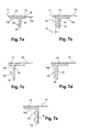
- a thickness 21 of this protrusion 18 orthogonally to the X axis can be uniform, as shown in Figures 1 to 6. But in variant, as shown in FIGS. 7a to 7e, this thickness 21 can be variable along the X axis. This thickness varies between 0.2 mm and 2 mm, and is preferably between 0.5 mm and 1 mm.
- the protrusion 18 is provided, at a distal end 24 opposite to a zone of attachment to the lower face 19, a protuberance 25 extending laterally relative to the axis of elongation of the outgrowth 18, in particular extending laterally relative to the axis X.
- this protuberance 25 may be of cross section hemispherical.
- the distal end 24 then forms an annular bead to the free end of the skirt.
- the protrusion 25 can be made at all levels along the protuberance 18 relative to the axis X.
- the protrusion 25 extends laterally in at least one oblique or perpendicular direction relative to the X axis.
- the protrusion 25 may form a harpoon.
- the protuberance 25 protrudes from the outer lateral edge 29 of the protuberance 18.
- This protuberance 25 is oriented towards the border 17 of the sieve.
- the distance 22 is by consequently measured by projecting, along the X axis, the border 17 and the shape of the protrusion 18 provided with its protuberance 25 on a plane orthogonal to this axis X.
- the protrusion 25 has a cross section, in a cutting plane orthogonal to the plane of the sieve 12, forming a triangle disposed at the distal end of the outgrowth 18.
- the protrusion 25 has a cross section forming a triangle disposed at half height of the protrusion 18.
- the protrusion 18 comprises several protuberances such 25, in this case respectively three and two protuberances such as 25, each oriented on the same side of the outer lateral edge 29.
- the protrusion 18 does not have any protuberances at its inner side edge.
- the protrusion 18 can be formed in the formed zone by the grid 16.
- the protrusion 18 can be obtained from a durable deformation of a plane formed by grid 16.
- the housing 4 comprises a powder puff 26 disposed above the sieve 12.
- the powder puff 26 is constituted by example of a foam that can be flocked or not.
- the puff 26 is maintained in the receptacle 2 by the lid 3.
- the opening of the lid 3, allows the user to take the puff 26 and then apply it against the grid 16 of the sieve, as illustrated in Figure 5.
- the user pushes the sieve into the product P and the product passes through the grid to impregnate the puff 26 and then allow a application by means of this puff on a surface to make up, for example the face, or more precisely the cheeks or the eyelids.
- the user can, before opening the lid 3, shake the housing 1.
- the product then passes through the grid and can come cover the face of the puff 26 facing the sieve.
- the puff 26 is then immediately ready for use, as soon as lid 3 is opened. anchoring system provided by the protrusion 18, even by subjecting the housing 1 to such treatment, the sieve 12 remains anchored and attached to the product.
- the product does not do not disintegrate excessively.
- the bottom 11 has a complementary relief of the sieve 12 so that at the end of use, the sieve can be attached almost in every way with this background.
- the bottom 11 has a groove 27 adapted to receive the protrusion 18.
- the groove 27 also participates in the retention of the sieve 12 attached to the product P, in the end of use of the product.
- the groove 27 may in a complementary manner also be provided annular.
- the bottom 11 has a relief adapted so that at the end of use, the lower face 19b of the grid 16 can less to be almost contiguous against a surface of this bottom.
- a housing 1 according to the invention can have a mirror 28 for example integral with the lid 3.
- This housing 1 may more present means 30 for external fixation on a device complementary.
- the complementary device may be a device for packaging and distribution of a product complementary to the product P.
- this complementary device may be an accessory or a device for conditioning of such an accessory.
- This accessory can be a mirror or an applicator.
Landscapes
- Combined Means For Separation Of Solids (AREA)
- Closures For Containers (AREA)
Applications Claiming Priority (2)
| Application Number | Priority Date | Filing Date | Title |
|---|---|---|---|
| FR0450736A FR2868919B1 (fr) | 2004-04-20 | 2004-04-20 | Boitier cosmetique |
| FR0450736 | 2004-04-20 |
Publications (1)
| Publication Number | Publication Date |
|---|---|
| EP1588644A1 true EP1588644A1 (de) | 2005-10-26 |
Family
ID=34942154
Family Applications (1)
| Application Number | Title | Priority Date | Filing Date |
|---|---|---|---|
| EP05290854A Withdrawn EP1588644A1 (de) | 2004-04-20 | 2005-04-18 | Schminkdose |
Country Status (2)
| Country | Link |
|---|---|
| EP (1) | EP1588644A1 (de) |
| FR (1) | FR2868919B1 (de) |
Cited By (6)
| Publication number | Priority date | Publication date | Assignee | Title |
|---|---|---|---|---|
| FR3045294A1 (fr) * | 2015-12-17 | 2017-06-23 | Oreal | Dispositif de conditionnement et d'application a tamis solidaire d'un support annulaire pose librement sur le produit a appliquer |
| WO2017140680A1 (en) | 2016-02-19 | 2017-08-24 | L'oreal | Device comprising a screen with rigid lips |
| US20170354223A1 (en) * | 2014-12-30 | 2017-12-14 | L'oreal | Refill for inserting into a device for treating the hair by pivoting |
| US10039366B1 (en) | 2014-09-25 | 2018-08-07 | Snugz/Usa Incorporated | Dual balm applicator and method of manufacture |
| WO2018178550A1 (fr) * | 2017-03-31 | 2018-10-04 | Chanel Parfums Beaute | Articlede cosmétique muni d'une maille |
| WO2021074518A1 (fr) * | 2019-10-17 | 2021-04-22 | L V M H Recherche | Dispositif de conditionnement de produit cosmétique |
Citations (2)
| Publication number | Priority date | Publication date | Assignee | Title |
|---|---|---|---|---|
| JPH09140444A (ja) * | 1995-11-24 | 1997-06-03 | Shiseido Co Ltd | ネット付き化粧料容器 |
| FR2838618A1 (fr) * | 2002-04-18 | 2003-10-24 | Oreal | Dispositif de conditionnement et de distribution d'un produit au travers d'un tamis monte sur un support compressible |
Family Cites Families (1)
| Publication number | Priority date | Publication date | Assignee | Title |
|---|---|---|---|---|
| JP2728216B2 (ja) * | 1989-07-07 | 1998-03-18 | 田中電子工業株式会社 | 半導体素子のボンディング用金線 |
-
2004
- 2004-04-20 FR FR0450736A patent/FR2868919B1/fr not_active Expired - Fee Related
-
2005
- 2005-04-18 EP EP05290854A patent/EP1588644A1/de not_active Withdrawn
Patent Citations (2)
| Publication number | Priority date | Publication date | Assignee | Title |
|---|---|---|---|---|
| JPH09140444A (ja) * | 1995-11-24 | 1997-06-03 | Shiseido Co Ltd | ネット付き化粧料容器 |
| FR2838618A1 (fr) * | 2002-04-18 | 2003-10-24 | Oreal | Dispositif de conditionnement et de distribution d'un produit au travers d'un tamis monte sur un support compressible |
Non-Patent Citations (1)
| Title |
|---|
| PATENT ABSTRACTS OF JAPAN vol. 1997, no. 10 31 October 1997 (1997-10-31) * |
Cited By (11)
| Publication number | Priority date | Publication date | Assignee | Title |
|---|---|---|---|---|
| US10039366B1 (en) | 2014-09-25 | 2018-08-07 | Snugz/Usa Incorporated | Dual balm applicator and method of manufacture |
| US20170354223A1 (en) * | 2014-12-30 | 2017-12-14 | L'oreal | Refill for inserting into a device for treating the hair by pivoting |
| US11344094B2 (en) * | 2014-12-30 | 2022-05-31 | L'oreal | Refill for inserting into a device for treating the hair by pivoting |
| FR3045294A1 (fr) * | 2015-12-17 | 2017-06-23 | Oreal | Dispositif de conditionnement et d'application a tamis solidaire d'un support annulaire pose librement sur le produit a appliquer |
| WO2017140680A1 (en) | 2016-02-19 | 2017-08-24 | L'oreal | Device comprising a screen with rigid lips |
| FR3047881A1 (fr) * | 2016-02-19 | 2017-08-25 | Oreal | Dispositif comportant un tamis avec des levres rigides |
| WO2018178550A1 (fr) * | 2017-03-31 | 2018-10-04 | Chanel Parfums Beaute | Articlede cosmétique muni d'une maille |
| FR3064458A1 (fr) * | 2017-03-31 | 2018-10-05 | Chanel Parfums Beaute | Article de cosmetique muni d'une maille |
| CN110461419A (zh) * | 2017-03-31 | 2019-11-15 | 香奈儿香水美妆品公司 | 设置有网状物的化妆品制品 |
| WO2021074518A1 (fr) * | 2019-10-17 | 2021-04-22 | L V M H Recherche | Dispositif de conditionnement de produit cosmétique |
| FR3102047A1 (fr) * | 2019-10-17 | 2021-04-23 | L V M H Recherche | Dispositif de conditionnement de produit cosmétique |
Also Published As
| Publication number | Publication date |
|---|---|
| FR2868919A1 (fr) | 2005-10-21 |
| FR2868919B1 (fr) | 2006-09-22 |
Similar Documents
| Publication | Publication Date | Title |
|---|---|---|
| CA2405042C (fr) | Dispositif de conditionnement d'un produit liquide ou en poudre | |
| EP1086904B1 (de) | Vorrichtung zur Aufnahme und Auftragung eines Produktes | |
| EP0923323B1 (de) | Spender für streichfähige produkte | |
| CA2410915C (fr) | Ensemble de conditionnement et d'application d'un produit | |
| EP1913835B1 (de) | Vorrichtung zur Verpackung und Anwendung | |
| CA2337184C (fr) | Dispositif de conditionnement et d'application comportant un element formant reservoir intermediaire | |
| WO1997031837A1 (fr) | Tete et ensemble de distribution de produit de consistance liquide a visqueuse, comportant un reducteur d'ecoulement | |
| EP1208916B1 (de) | Verbesserte Vorrichtung zur Verpackung und der dosierten Abgabe von Flüssigkeit | |
| FR2875110A1 (fr) | Dispositif d'application d'un produit muni d'un organe d'application amovible | |
| EP1174190A1 (de) | Aufbewahrungs- und Spendevorrichtung zur Abgabe einer einstellbaren Dosierung | |
| EP1557111A1 (de) | Applikator mit einem Auftragselement, welcher mit einem Produktbehälter verbunden ist | |
| EP1520798B1 (de) | Vorrichtung zur Verpackung und zur Anwendung eines kosmetischen Produkts | |
| EP1649775A1 (de) | Auftragsspender für Erzeugnisse, insbesondere zur Schönheitspflege | |
| EP1673998B1 (de) | Vorrichtung zum Aufbewahren und Auftragen eines kosmetischen Produkts | |
| EP1588644A1 (de) | Schminkdose | |
| EP1428454B1 (de) | Applikator sowie Verpackung- und Auftragungseinheit mit einem solchen Applikator | |
| CA2411718C (fr) | Dispositif pour le conditionnement et la distribution dosee d'un produit liquide | |
| EP1174355A1 (de) | Vorrichtung zum Aufbewahren und Ausgeben eines kapillaren Produktes | |
| EP1797790A1 (de) | Vorrichtung zum Aufbewahren und Auftragen mit einem einstellbaren Abstreifelement | |
| FR3104011A1 (fr) | Article cosmétique pour la distribution d’au moins une composition cosmétique | |
| FR2870439A1 (fr) | Base de support en particulier pour produits cosmetiques, et ensemble base de support/recharge | |
| EP1502872B1 (de) | Vorrichtung mit einem Doppelabgabesystem | |
| FR2918648A1 (fr) | Dispositif de conditionnement et d'application d'un produit cosmetique | |
| FR3009934A1 (fr) | Boite de distribution pour produit en poudre | |
| FR3111777A1 (fr) | Ensemble de conditionnement et de distribution de produit comprenant un organe d’application de produit pourvu d’orifices à section variable en continu |
Legal Events
| Date | Code | Title | Description |
|---|---|---|---|
| PUAI | Public reference made under article 153(3) epc to a published international application that has entered the european phase |
Free format text: ORIGINAL CODE: 0009012 |
|
| AK | Designated contracting states |
Kind code of ref document: A1 Designated state(s): AT BE BG CH CY CZ DE DK EE ES FI FR GB GR HU IE IS IT LI LT LU MC NL PL PT RO SE SI SK TR |
|
| AX | Request for extension of the european patent |
Extension state: AL BA HR LV MK YU |
|
| 17P | Request for examination filed |
Effective date: 20060426 |
|
| AKX | Designation fees paid |
Designated state(s): AT BE BG CH CY CZ DE DK EE ES FI FR GB GR HU IE IS IT LI LT LU MC NL PL PT RO SE SI SK TR |
|
| 17Q | First examination report despatched |
Effective date: 20070622 |
|
| STAA | Information on the status of an ep patent application or granted ep patent |
Free format text: STATUS: THE APPLICATION IS DEEMED TO BE WITHDRAWN |
|
| 18D | Application deemed to be withdrawn |
Effective date: 20151103 |