EP1174190A1 - Aufbewahrungs- und Spendevorrichtung zur Abgabe einer einstellbaren Dosierung - Google Patents
Aufbewahrungs- und Spendevorrichtung zur Abgabe einer einstellbaren Dosierung Download PDFInfo
- Publication number
- EP1174190A1 EP1174190A1 EP01401861A EP01401861A EP1174190A1 EP 1174190 A1 EP1174190 A1 EP 1174190A1 EP 01401861 A EP01401861 A EP 01401861A EP 01401861 A EP01401861 A EP 01401861A EP 1174190 A1 EP1174190 A1 EP 1174190A1
- Authority
- EP
- European Patent Office
- Prior art keywords
- bellows
- container
- adjustment member
- adjusting member
- product
- Prior art date
- Legal status (The legal status is an assumption and is not a legal conclusion. Google has not performed a legal analysis and makes no representation as to the accuracy of the status listed.)
- Withdrawn
Links
Images


Classifications
-
- G—PHYSICS
- G01—MEASURING; TESTING
- G01F—MEASURING VOLUME, VOLUME FLOW, MASS FLOW OR LIQUID LEVEL; METERING BY VOLUME
- G01F11/00—Apparatus requiring external operation adapted at each repeated and identical operation to measure and separate a predetermined volume of fluid or fluent solid material from a supply or container, without regard to weight, and to deliver it
- G01F11/02—Apparatus requiring external operation adapted at each repeated and identical operation to measure and separate a predetermined volume of fluid or fluent solid material from a supply or container, without regard to weight, and to deliver it with measuring chambers which expand or contract during measurement
- G01F11/08—Apparatus requiring external operation adapted at each repeated and identical operation to measure and separate a predetermined volume of fluid or fluent solid material from a supply or container, without regard to weight, and to deliver it with measuring chambers which expand or contract during measurement of the diaphragm or bellows type
- G01F11/082—Apparatus requiring external operation adapted at each repeated and identical operation to measure and separate a predetermined volume of fluid or fluent solid material from a supply or container, without regard to weight, and to deliver it with measuring chambers which expand or contract during measurement of the diaphragm or bellows type of the squeeze container type
-
- A—HUMAN NECESSITIES
- A45—HAND OR TRAVELLING ARTICLES
- A45D—HAIRDRESSING OR SHAVING EQUIPMENT; EQUIPMENT FOR COSMETICS OR COSMETIC TREATMENTS, e.g. FOR MANICURING OR PEDICURING
- A45D34/00—Containers or accessories specially adapted for handling liquid toiletry or cosmetic substances, e.g. perfumes
-
- B—PERFORMING OPERATIONS; TRANSPORTING
- B05—SPRAYING OR ATOMISING IN GENERAL; APPLYING FLUENT MATERIALS TO SURFACES, IN GENERAL
- B05B—SPRAYING APPARATUS; ATOMISING APPARATUS; NOZZLES
- B05B11/00—Single-unit hand-held apparatus in which flow of contents is produced by the muscular force of the operator at the moment of use
- B05B11/0005—Components or details
- B05B11/0027—Means for neutralising the actuation of the sprayer ; Means for preventing access to the sprayer actuation means
- B05B11/0029—Valves not actuated by pressure
-
- B—PERFORMING OPERATIONS; TRANSPORTING
- B05—SPRAYING OR ATOMISING IN GENERAL; APPLYING FLUENT MATERIALS TO SURFACES, IN GENERAL
- B05B—SPRAYING APPARATUS; ATOMISING APPARATUS; NOZZLES
- B05B11/00—Single-unit hand-held apparatus in which flow of contents is produced by the muscular force of the operator at the moment of use
- B05B11/0005—Components or details
- B05B11/0059—Components or details allowing operation in any orientation, e.g. for discharge in inverted position
-
- B—PERFORMING OPERATIONS; TRANSPORTING
- B05—SPRAYING OR ATOMISING IN GENERAL; APPLYING FLUENT MATERIALS TO SURFACES, IN GENERAL
- B05B—SPRAYING APPARATUS; ATOMISING APPARATUS; NOZZLES
- B05B11/00—Single-unit hand-held apparatus in which flow of contents is produced by the muscular force of the operator at the moment of use
- B05B11/01—Single-unit hand-held apparatus in which flow of contents is produced by the muscular force of the operator at the moment of use characterised by the means producing the flow
- B05B11/04—Deformable containers producing the flow, e.g. squeeze bottles
- B05B11/048—Deformable containers producing the flow, e.g. squeeze bottles characterised by the container, e.g. this latter being surrounded by an enclosure, or the means for deforming it
Definitions
- the present invention relates to packaging devices and application of a product, especially a cosmetic and / or skincare product, and aims more particularly those intended for the application of a product to hair and / or leather Scalp.
- the user has to use his thumb and index finger to compress the bellows, pressing the pushers in a direction transverse to the axis bellows.
- This device has a relatively complex structure due to the use pushers.
- the device comprises a dispensing nozzle having a breakable part
- the applicant company has found that the application of the product to the base hair, with the tip coming into contact with the scalp, could be uncomfortable because the tip is likely to present, after removal of the part breakable, an angular edge which can scratch the scalp or catch the hair.
- the present invention relates to a device for packaging and distribution intended in particular for the application of a cosmetic and / or care product, especially on the hair and / or scalp, which is relatively constructed simple and inexpensive, easy to use, and which allows you to vary the dose of product distributed.
- the packaging and distribution device comprises a container comprising a bellows allowing the distribution of a dose of product in being compressed axially, this bellows comprising first and second regions approaching during its compression, the device comprising an adjustment member allowing to modify the bellows compression stroke and the quantity of product distributed, the device being characterized in that it is arranged in such a way that the bellows compression results from a push exerted by the user substantially in the axis of the bellows.
- the adjusting member moves with the first region of the bellows during compression of the latter and has a stop surface capable of coming resting on a surface forming a stop, fixed relative to the second region of the bellows at least during the compression of the bellows, so as to impose the travel of maximum compression of the bellows, the adjusting member being fixed on the device such so that the axial positioning of said stop surface can be modified before the bellows compression, depending on the quantity of product to be dispensed.
- the user can easily and easily choose reproducible the dose of product dispensed, while having a relatively simple device and inexpensive to manufacture.
- the bellows communicates with a bottle body by through a strangled part.
- Such a choked part facilitates the gripping of the device and allows in particular, if the dispensing nozzle allows, compression of the bellows by exerting a push with the thumb on one side of the bellows and with the middle and index finger on the other side of the bellows, the middle and index finger being engaged in the groove formed around the part strangled.
- the device comprises first and second surfaces support located respectively on either side of the bellows, to allow the user to exert pressure in the axis of the container to bring said support surfaces and compress the bellows, the first support surface being located on a dispensing tip or close to it, so that the user can dispense the product by holding the device with one hand and can also bring the latter to contact with the surface to which the product is to be applied.
- This configuration notably allows the user to easily control with his hand the distance between the dispensing nozzle and the surface to be treated or the application pressure of the nozzle thereon.
- the user can thus move the nozzle precisely along the surface to be treated without there being any contact of the nozzle with it, using his hand, preferably with his thumb.
- the user can also distribute the product in his other hand before apply it on the surface to be treated.
- the user when using a breakable tip, the user can avoid a contact between the nozzle and the surface to be treated.
- the bellows is made in one piece with the bottle body.
- the axis of the bellows coincides with that of the body of bottle.
- the volume of the bottle body can be at least ten times that of the bellows when the latter is in the uncompressed state.
- the device may include means for fixing the adjustment member to the device allowing continuous adjustment of the maximum compression stroke of the bellows.
- These means may include a thread made on the neck of the container or on a patch.
- the device When a thread is used, the device preferably includes a boss and the adjusting member comprises at least one relief capable of elastically crossing this boss when screwing the adjusting member onto the container, the boss being shaped so as to prevent the complete unscrewing of the adjusting member.
- the device can also include a succession of reliefs located at different levels compared to the first region of the bellows, and the adjusting member include at least one positioning element capable of cooperating with these reliefs to axially immobilizing the adjusting member in a predetermined axial position by relative to the first region of the bellows.
- Such reliefs can be constituted by a succession of ribs creating grooves between them in which the element of positioning.
- the ribs each extend over a angular sector limited around the axis of the container, and the positioning element of the adjustment member extends over an angular sector chosen so as to allow disengage after a rotational movement around the axis of the container the element of positioning of the grooves formed between said ribs to modify the axial positioning of the adjusting member and the quantity of product dispensed when the bellows is compressed.
- the reliefs in question can be made on an attachment on the container.
- these reliefs are produced during the molding of the container.
- the surface forming a stop is defined by part of the device.
- the abutment surface can be defined by a wall cross-section of the container.
- the abutment surface can be located inside the container.
- the adjustment member comprises an extension extending inside the bellows, able to bear against said surface forming a stop when the bellows is compressed.
- said extension is constituted by the lower part of a inner sealing skirt applying tightly to a container neck.
- the surface forming a stop can in particular be defined by a wall transverse on which the bellows is connected.
- said surface forming stop is defined by a portion of the outer surface of the container.
- the surface forming stop is defined by a fold of the bellows.
- the bellows advantageously has a cross section elliptical and the adjusting member comprises at least one relief defining said surface stop, able to bear against a fold of the bellows in an angular position predetermined adjustment member relative to the container and able to move freely between the folds of the bellows in another predetermined angular position of the adjusting member relative to the container.
- the adjustment member has a wall located outside the container, defining said stop surface.
- this wall is constituted by a tubular skirt of diameter interior superior to that of the bellows when the latter is in the compressed state, this skirt being able to bear on a transverse wall of the container to which it is connected the bellows.
- the adjustment member is able to come hang on a part of the container so as to keep the bellows in the compressed state during storage, which facilitates packaging.
- the adjustment member includes teeth capable of snapping on said part of the container, which simplifies manufacture.
- the adjustment member is able to snap on a part of the container having a non-circular radially outer edge, so as to allow the adjustment member to be disengaged from said part of the container after a rotation of the adjusting member relative to the container.
- the device comprises a dispensing tip carried by the regulating member.
- the adjusting member then advantageously comprises a passage allowing the product in the container to reach the dispensing tip.
- the dispensing end piece can be articulated on the adjustment member.
- the adjustment member preferably comprises a wall device for masking a product outlet orifice from the nozzle, when this the latter is in a first position relative to the adjustment member, the end piece being tilt to take a second position in which the outlet is no longer hidden by the peripheral wall of the adjuster, when the user presses the mouthpiece.
- the dispensing nozzle is subject to a deformable wall allowing relative axial displacement of the dispensing nozzle by relative to the adjusting member.
- this deformable wall has a stepped tubular shape.
- the tip causes its movement relative to the adjusting member a shutter, arranged to isolate the interior of the container from the outside when the device is not used.
- the invention also relates to a device for packaging and distribution comprising a container comprising a bellows, the bellows allowing the distribution of a dose of product by being compressed axially, and a regulating member allowing to modify the bellows compression stroke and the quantity of product distributed, characterized in that it further comprises a dispensing nozzle and first and second bearing surfaces located respectively on either side of the bellows, to allow the user to exert pressure on the axis of the container to bring said bearing surfaces closer together and compress the bellows, the dispensing nozzle comprising an outlet orifice situated near the first bearing surface, on the side of the device.
- the invention also relates to a device for packaging and distribution comprising a container comprising a bellows, the bellows allowing the distribution of a dose of product by being compressed axially, and a regulating member allowing continuous modification of the bellows compression stroke and the quantity of distributed product, characterized in that it is arranged in such a way that the bellows compression results from an axial thrust exerted by the user on the bellows.
- the invention also relates to a device for packaging and distribution comprising a container comprising a bellows, the bellows allowing the distribution of a dose of product by being compressed axially, and a regulating member allowing to modify the bellows compression stroke and the quantity of product distributed, characterized in that it is arranged in such a way that the compression of the bellows results from an axial thrust exerted by the user on the bellows and thereby that the bellows communicates with a bottle body via a part strangled.
- the invention also relates to a device for packaging and distribution comprising a container comprising a bellows, the bellows allowing the distribution of a dose of product by being compressed axially, and a regulating member allowing to modify the bellows compression stroke and the quantity of product distributed, characterized in that it is arranged in such a way that the compression of the bellows results from a thrust exerted by the user substantially in the axis of the bellows and by the fact that it has no valve.
- the invention also relates to a device for packaging and distribution comprising a container comprising a bellows, the bellows allowing the distribution of a dose of product by being compressed axially, and a regulating member allowing to modify the bellows compression stroke and the quantity of product distributed, characterized in that it is arranged in such a way that the compression of the bellows results from a push exerted by the user by means of his thumb.
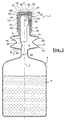
- the packaging and distribution device 1 shown in Figures 1 and 2 comprises a container comprising at its lower part a bottle body 2 and at its upper part a bellows 6 with shape memory, axis X, with a throttled part 4 between the two.
- the bellows 6 defines an interior space 5 of variable volume, used to distribute a dose of product, as will be explained below.
- the bottle body 2 contains a product A which can be a liquid more or less viscous, even a paste.
- product A consists of a shampoo or other hair or scalp product.
- the bellows 6 is connected superiorly, by a first region 6a, to a transverse wall 8, which is extended upwards by a neck 14 of axis X.
- the bellows 6 is connected below, by a second region 6b, to a transverse wall 9 extending upwards the constricted part 5.
- the bellows 6 comprises in the example described a fold located substantially at mid-distance between the transverse walls 8 and 9.
- the wall of the bellows 6 has a reduced thickness compared to the walls 8 and 9.
- the bottle body 2 forms, with the transverse wall 9, an annular groove 12 around the strangled part 4, into which the middle finger M and the user's index I, as illustrated in FIG. 2.
- the underside of the transverse wall 9 then defines a bearing surface 3 for the user's M major and I index.
- the neck 14 has an external thread 19 extending substantially over the half its length from its upper end 18.
- annular boss 22 is produced under the thread 19 on the outer surface of the neck 14.
- the neck 14 has a symmetrical inner surface of revolution around the X axis, with a slight offset 14a inwards in the vicinity of its end upper 18.
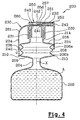
- the device 1 comprises an adjustment member 30 screwed onto the neck 14.
- This adjustment member 30 includes an outer mounting skirt 31, and an inner skirt 40, engaged inside the neck 14, the two skirts 31 and 40 being coaxial and joined at their upper end by a transverse wall 32.
- the mounting skirt 31 is internally threaded on about two-thirds of its length from the transverse wall 32 and comprises at its lower end, on its radially inner surface, teeth 36 shaped to cross by deformation elastic the boss 22 of the neck 14.
- the teeth 36 are shaped so as to prevent the complete unscrewing of the mounting skirt 31, abutting against the underside of the boss 22, substantially perpendicular to the X axis.
- the inner skirt 40 has an enlarged upper part 43, shaped to apply sealingly on the inner surface of the neck 14 in the vicinity of the upper end 18 of the latter.
- the length of the upper part 43 is chosen so that it remains in tight contact with the inner surface of the neck 14 over the entire adjustment stroke, the adjusting member 30 is fully screwed onto the neck 14, the transverse wall 32 coming while pressing on the end 18 thereof, or unscrewed to the maximum, the teeth 36 coming resting against the boss 22.
- the inner skirt 40 is extended downwards, beyond the upper part widened 43, by a lower part 41 of smaller diameter than this one, perforated longitudinally, the lower end 42 of which defines a stop surface in the sense of the invention.
- the inner skirt 40 comes to bear by its lower end 42 against the transverse wall 9, the upper face 59 of which defines a surface forming a stop within the meaning of the invention.
- the transverse wall 32 has an eccentric orifice 45, of axis Y parallel to the X axis, surrounded by an annular lip 46 directed upwards.
- the adjusting member 30 comprises, above the transverse wall 32, a peripheral wall 47 defining a housing for receiving a dispensing nozzle 50.
- the peripheral wall 47 defines, on the side opposite to the orifice 45, an opening 49 allowing the user to press on the nozzle 50, as will be explained below.
- the end piece 50 is articulated on the member of adjustment 30 around a geometric axis of rotation perpendicular to the X axis and to the plane section of Figure 1.
- the tip 50 includes a housing 54 in which the annular lip engages 46, with the possibility of displacement along the Y axis.
- a shutter pin 58 is made in the bottom of the housing 54 to seal sealingly the passage defined by the lip 46 when the nozzle occupies the position of closure shown in Figure 1.
- An outlet channel 52 is produced in the end piece 50 and communicates with the housing 54 above.
- this outlet channel 52 is masked by the wall peripheral 47 when the end piece 50 is in its closed position.
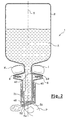
- the upper face of the end piece 50 defines, on the side of the opening 49, a bearing surface 51 allowing the user to compress the bellows 6 with his thumb P, as shown in figure 2.
- the end piece 50 toggles first which allows the outlet channel 52 to disengage from the wall device 47.
- the user Before using the device 1, the user can adjust the distance d between the lower end 42 of the inner skirt 40 and the transverse wall 9, by more or less screwing the adjusting member 30 onto the neck 14.
- the quantity corresponding to the adjustment can be viewed, by example, by means of graduations inscribed on the neck 14, these graduations being gradually discovered as the adjusting member 30 is unscrewed and therefore the compression stroke of the bellows 6 is important.
- the compression of the bellows 6 causes a decrease in the internal volume of the container and the air compression above product A, which causes its expulsion through the outlet channel 52.
- FIG. 3 shows a device 100 which comprises a container which does not differing from that described above only by the presence on the neck 14, under the boss annular 22, two beads 101 and 102 forming between them an annular groove 103 whose role will be explained later.
- the device 100 comprises an adjustment member 130 comprising a skirt interior 40, identical to that described with reference to FIG. 1, a mounting skirt 131, outer to the collar 14, and an outer skirt for covering 132.
- the inner 40, mounting 131 and outer 132 skirts are combined superiorly by a transverse wall 135.
- the mounting skirt 131 has an internal thread 136 engaging with the thread 19 of the neck 14 and, at its lower end, an annular boss 140 suitable for cross the boss 22 and the beads 101 and 102 by elastic deformation.
- the boss 22 is opposed, as in the example described above, to the complete unscrewing of the adjustment member 130, taking into account the inclination of its face lower.
- the beads 101 and 102 can be crossed by boss 140 in the two sense and the latter can be housed in the annular groove 103.
- the hard point linked to the crossing of the bead 101 or 102 provides information the user in the axial position of the adjusting member 130 relative to the neck 14.
- the annular groove 103 corresponds to a predetermined axial positioning of the adjusting member 130 on the neck 14, for dispensing an average dose for example.
- the adjustment member 130 comprises, above the transverse wall 135, a distribution nozzle 150, located between two lateral extensions 160, only one of which is visible in figure 3.
- the dispensing nozzle 150 is connected to the transverse wall 135 by a stepped tubular wall 161.
- This stepped tubular wall is connected to the transverse wall 135 by a frustoconical wall 162 serving as a seat for a shutter 170.
- the nozzle 150 has an outlet channel 152, of axis Z perpendicular to the X axis.
- hooking lugs 154 extend downward around the orifice 153 and each have at their lower end, and on their face radially interior, a tooth 155.
- the shutter 170 comprises a plate 171 provided with a flange 172 directed towards the bottom, capable of being applied in a sealed manner on the frustoconical wall 162, and a rod 174 extending upward the tray 171.
- the rod 174 has an enlarged lower part 176 provided with a bead annular 175 able to snap between the legs 154 above the teeth 155 and, above of this enlarged part 176, an upper part 177 of markedly diameter lower than that of orifice 153, extending to the vicinity of the upper wall 159 of the nozzle 150.
- the inside of the container is thus isolated from the outside.
- the upper wall 159 of the end piece 150 defines a bearing surface for the user, whose level is below the upper end of the lateral extensions 160, so that the end piece 150 is thus protected against accidental penetration.
- the lateral extensions 160 also help to facilitate positioning of the user's finger on the tip 150.
- the user positions the device 100 upside down and presses on the dispensing nozzle 150, which has the effect of causing in a first the deformation of the tubular wall 161 taking into account the fact that it opposes in the example describes a lower penetration resistance than the force required to compress the bellows 6.
- the upper part 177 comes to bear, by its upper end 179, against the upper wall 159, this which causes the shutter 171 to move apart from its seat and allows the product to gain the output channel 152.
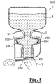
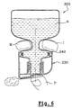
- FIG. 4 shows a device 200 comprising a container comprising at its lower part a bottle body 202 and at its upper part a bellows 206.
- the container also has a constricted portion 204 between the body of bottle 202 and the bellows 206, this constricted part 204 being extended superiorly by a transverse wall 209.
- the bellows 206 is connected superiorly by a first region 206a to a transverse wall 208, which is extended upwards by a neck 214, the latter having an external thread 220 at its upper part.
- the bellows 206 is connected below by a second region 206b on the transverse wall 209, slightly set back from its peripheral edge 213, so as to form a flange 210 whose role will be explained later.
- the device 200 comprises an adjustment member 230, which comprises a outer skirt 234, the latter surrounding a threaded mounting skirt 231 internally and screwed onto the neck 214.
- the adjusting member 230 also includes an internal skirt 230 capable of apply tightly to the inner surface of the neck 214.
- the outer skirt 234 is provided at its lower end and on its surface radially inner of teeth 236.
- the transverse wall 208 has on its radially outer edge a annular ridge 224, of external diameter corresponding substantially to the diameter inside of the outer skirt 234, shaped to be easily crossed by the teeth 236 when the adjusting member 230 is screwed onto the neck 214 and having a lower face substantially perpendicular to the X axis, so as to prevent complete unscrewing of the adjusting member 230.
- the mounting skirt 231 and the internal skirt 240 are connected to a wall transverse 232 crossed by an orifice 241.
- the latter is surrounded by an annular lip 242 extending above the transverse wall 232.
- the adjusting member 230 includes above the transverse wall 232 a peripheral wall 243 defining a housing in which is fixed a nozzle distribution 250, the latter being articulated on the peripheral wall 243 about an axis geometric rotation perpendicular to the X axis and to the plane of Figure 4.
- the end piece 250 has an outlet channel 251, the end 252 of which is located in front of the peripheral wall 243 when the end piece 250 is in its closed position, corresponding to figure 4.
- the tip 250 has a housing 256 in which the lip engages annular 242, provided with a closing pin 257 closing the passage defined by the annular lip 242 when the end piece 250 is in its closed position.
- the peripheral wall 243 is perforated, on the side opposite the end 252, so allow the user to press on a bearing surface 260 defined by the face upper end.
- the outer skirt 234 is connected to the transverse wall 232 on the side of the bearing surface 260 by a rounded 261, making it more comfortable for the user actuation of the device.
- the outer skirt 234 is able to bear, by its lower end 242, on the flange 210 when the bellows 206 is compressed axially.
- the distance d which determines the maximum compression stroke of the bellows 206 can be adjusted.
- the dispensing nozzle 250 When the user presses on the dispensing nozzle 250, the latter pivots by so as to bring the end 252 of the outlet channel above the peripheral wall 243, like the embodiment of Figures 1 and 2 described above, then the bellows 206 is compressed.
- FIG. 5 shows the device 200 when the outer skirt 234 comes into abutment against the flange 210, at the end of compression of the bellows 206.
- the device 300 shown in Figure 6 differs from that described with reference in Figures 4 and 5 by the absence of a flange 210, the surface forming a stop in the sense of the invention being defined by the fingers of the user.
- the device 400 shown in Figure 7 includes a container comprising lower part a bottle body 402 and upper part a bellows 406, of axis X, connected to the bottle body 402 by a constricted part 404.
- transverse wall 409 The latter is extended above by a transverse wall 409.
- the bellows 406 is connected superiorly by a first region 406a to a transverse wall 408 extended upwards by a neck 414, of axis X.
- the bellows 406 is connected to the transverse wall 409 by a second region 406b slightly set back from its peripheral edge 413, so as to form a flange 410 like the device described with reference to Figures 4 and 5.
- Col 414 differs from those of the previous examples in that it does not has no external thread but a simple annular boss 424.
- the device 400 comprises an adjustment member 430 comprising a skirt outer 431, of axis X, able to bear by its lower end 442 against the flange 410 when the bellows 406 is compressed.
- the outer skirt 431 is connected above a transverse wall 432, having on its inner side a flange 433 directed downwards.
- the adjustment member 430 has an inner skirt 434 which is connected above the transverse wall 432 and of lesser height than the outer skirt 431, so as not to come to bear on the bellows 406.
- the device 400 includes a distribution assembly 460, comprising a mounting skirt 461 provided with teeth 465 capable of snapping onto the boss 424 of the neck 414 and an inner lip 462 capable of being applied in a sealed manner to the surface radially inside of the neck 414.
- the mounting skirt 461 and the inner lip 462 are connected above an annular wall 463, extended upwards, in two locations diametrically opposite, by lateral uprights 470, parallel to the X axis.
- the uprights 470 are provided at their upper end with fins transverse 471, directed outwards, having a radially outer edge 472 circular of axis X, of radius substantially equal to that of the outer skirt 431.
- the fins 472 have rectilinear inner edges 473, facing each other, parallel and leaving between them an opening allowing the user to press on a distribution nozzle 450 located between the uprights 470, as can be seen on the figure 8.
- the dispensing nozzle 450 has a structure identical to the nozzle 150 described with reference to FIG. 3 and is connected to the annular wall 463 by a wall stepped tubular 455, identical to the wall 161 previously described.
- a shutter 456 is integral with the end piece 450, this shutter 456 being identical to the shutter 171 previously described.
- the distribution assembly 460 is produced, with the exception of the shutter 456 which is reported later, in one piece by molding of thermoplastic material.
- the uprights 470 have on their radially outer face a succession of ribs 478, defining between them grooves 476 located at levels different along the X axis.
- the rim 433 extends over a limited angular sector, so as to allow axially uncoupling the adjustment member 430 and the distribution assembly 460.
- the user can thus, by rotating the adjusting member 430 relatively to the distribution assembly 460, bring it into a position in which the edges 433 come out of the grooves 476, which allows an axial displacement of the member setting 430 relative to the distribution assembly 460.
- the inner skirt 434 has an inner diameter substantially corresponding to the outside diameter of the ribs 478.
- the adjusting member 430 can be positioned in the example described in four different levels, the lower level being defined by the arrival of the inner skirt 434 in support on the transverse wall 408.
- the distance d between the lower end of the outer skirt 431 and the flange 410 is different, which makes it possible to expel a more or less significant dose of product when the bellows 406 is compressed.
- a device 500 which comprises a container comprising in the lower part a bottle body 502 and in part upper a bellows 506 and, between the two, a choked part 504.
- the bellows 506 is connected superiorly by a first region 506a to a transverse wall 508 extended upwards by a neck 514.
- the bellows 506 is connected below by a second region 506b to a transverse wall 509, which extends the throttled part 504 above.
- the neck 514 has two external threaded parts 520, diametrically opposed.
- the bottle body 502 has a transverse wall at the top 503, which defines with the transverse wall 509 an annular groove 510.
- the transverse wall 503 has at its periphery two reliefs 505 diametrically opposed, and the function of which will be specified below.
- the bellows 506 has, in cross section, an elliptical shape as you can see it in figure 10.
- the device 500 comprises a distribution assembly 560, comprising a mounting skirt 561 screwed onto the threaded parts 520 of the neck 514, and an interior skirt 540 sealingly applied to the radially inner surface of the neck 514.
- the mounting skirt 561 and the inner skirt 540 are connected at the top to a transverse wall 532.
- Distribution assembly 560 receives an identical distribution nozzle 550 to the dispensing nozzle described with reference to FIG. 1, the part of the assembly of distribution 560 which extends above the transverse wall 532 being identical to that of the adjusting member 30 which extends above the transverse wall 32.
- the device 500 comprises an adjustment member 530, comprising a skirt 531 cylindrical of axis X revolution, connecting at its upper end to a transverse wall 532 having a central opening 533 whose internal diameter corresponds to the outside diameter of the mounting skirt 561.
- Two teeth 536 are produced on the radially inner surface of the skirt 531, near its lower end, in diametrically located opposed.
- the transverse wall 532 has, as can be seen in FIG. 12, notches 534, opening onto the central opening 533, so as to allow the passage of threaded parts 520 when the adjustment member 530 is placed on the neck 514.
- the reliefs 505 extend over a limited angular sector around the axis X and provide between them, as can be seen in FIG. 10, spaces 580 of which the angular width is greater than that of teeth 536.
- the teeth 536 engage on the reliefs 505 or not.
- the device 500 can be kept in a storage configuration in which the bellows 506 is compressed and the teeth 536 come to bear under the reliefs 505, as illustrated in FIG. 9.
- the size of the device is thus reduced, which makes it possible to pack it more easily.
- the teeth 536 can, depending on the angular position of the adjusting member 530 relative to the container, engaging or not between the folds of the bellows 506, as illustrated in FIG. 13.
- the transverse wall 532 has openings 580 used for molding teeth 536.
- the mounting skirt 561 has, on its outer surface, a succession diametrically opposed ribs 590, including two ribs 592 at its end lower.
- the ribs 590 located on the same side are grouped in pairs, so forming between them three grooves 593 equidistant in the direction of the X axis.
- each of these grooves 593 is very slightly greater than the thickness of the transverse wall 532.
- the angular extent of the ribs 590 and 592 is less than that of the notches 534.
- the diameter of the radially outer edge 591 of the notches 534 is greater to that of ribs 590 or 592.
- the adjusting member 530 is in a position in which the notches 534 are offset by a quarter of a turn relative to the ribs 590 or 592.
- the bellows 506 is prevented to relax by pressing the teeth 536 against the reliefs 505.
- the adjusting member 530 can be brought into this position by snap-fastening teeth 536 on the reliefs 505, which makes automated manufacturing easier.
- the user turns the device by a quarter of a turn adjustment 530 relative to the container, which brings the ribs 592 vertically notches 534.
- the user can move the adjusting member 530 upwards until it brings the transverse wall 532 at a pair of grooves 593, for example the most low.
- the teeth 536 are then housed between two folds of the bellows 506.
- the lower faces 542 of teeth 536 defining stop surfaces within the meaning of the invention.
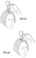
- FIGS. 14 and 15. The use of the device 200 of FIG. 4 has been illustrated in FIGS. 14 and 15. to apply a product on the hair.
Landscapes
- Physics & Mathematics (AREA)
- Fluid Mechanics (AREA)
- General Physics & Mathematics (AREA)
- Closures For Containers (AREA)
- Containers And Packaging Bodies Having A Special Means To Remove Contents (AREA)
- Auxiliary Devices For And Details Of Packaging Control (AREA)
Applications Claiming Priority (2)
| Application Number | Priority Date | Filing Date | Title |
|---|---|---|---|
| FR0009352A FR2811640B1 (fr) | 2000-07-17 | 2000-07-17 | Dispositif de conditionnement et de distribution permettant de distribuer une dose variable |
| FR0009352 | 2000-07-17 |
Publications (1)
| Publication Number | Publication Date |
|---|---|
| EP1174190A1 true EP1174190A1 (de) | 2002-01-23 |
Family
ID=8852591
Family Applications (1)
| Application Number | Title | Priority Date | Filing Date |
|---|---|---|---|
| EP01401861A Withdrawn EP1174190A1 (de) | 2000-07-17 | 2001-07-11 | Aufbewahrungs- und Spendevorrichtung zur Abgabe einer einstellbaren Dosierung |
Country Status (5)
| Country | Link |
|---|---|
| US (1) | US6758374B2 (de) |
| EP (1) | EP1174190A1 (de) |
| JP (2) | JP2002136337A (de) |
| CA (1) | CA2353316C (de) |
| FR (1) | FR2811640B1 (de) |
Cited By (4)
| Publication number | Priority date | Publication date | Assignee | Title |
|---|---|---|---|---|
| WO2003048694A1 (en) * | 2001-12-03 | 2003-06-12 | Cesare Signorini | A metering device for syrups and other fluids |
| ITTO20120060A1 (it) * | 2012-01-25 | 2013-07-26 | Inge Spa | Dispositivo per la conservazione di sostanze da mantenersi separate fino alla loro applicazione. |
| WO2014019898A1 (en) * | 2012-08-01 | 2014-02-06 | L'oreal | Device for dispensing a calibrated dose of cosmetic product |
| WO2014029575A1 (en) * | 2012-08-22 | 2014-02-27 | L'oreal | Transversely deformable bottle |
Families Citing this family (19)
| Publication number | Priority date | Publication date | Assignee | Title |
|---|---|---|---|---|
| US7028869B2 (en) * | 2002-07-15 | 2006-04-18 | L'oreal S.A. | Device and method for packaging at least one product and method for mixing at least two products |
| DE10333425A1 (de) * | 2003-07-17 | 2005-02-24 | Ing. Erich Pfeiffer Gmbh | Dosiervorrichtung mit einem Mediumspeicher |
| DE102009017459B4 (de) * | 2009-04-02 | 2017-02-23 | Aptar Radolfzell Gmbh | Austragvorrichtung |
| FR2985502B1 (fr) * | 2012-01-05 | 2014-01-17 | Oreal | Flacon et procede de conditionnement. |
| US9120108B2 (en) * | 2012-07-03 | 2015-09-01 | The Procter & Gamble Company | Foam generating dispenser |
| WO2016036761A1 (en) | 2014-09-02 | 2016-03-10 | HCT Group Holdings Limited | Container with dispensing tip |
| EP3193661A4 (de) | 2014-09-18 | 2018-04-04 | HCT Group Holding Limited | Behälter mit schnell lösbarer basis- und deckelanordnung |
| US20180029742A1 (en) * | 2015-02-12 | 2018-02-01 | Bosign Ab | A liquid dispensing device |
| EP3085459B1 (de) * | 2015-04-20 | 2017-08-09 | Aptar Radolfzell GmbH | Spendersystem |
| USD786088S1 (en) | 2015-07-10 | 2017-05-09 | HCT Group Holdings Limited | Angled pump with depression |
| US9993059B2 (en) | 2015-07-10 | 2018-06-12 | HCT Group Holdings Limited | Roller applicator |
| USD784162S1 (en) | 2015-10-08 | 2017-04-18 | HCT Group Holdings Limited | Tottle |
| USD818641S1 (en) | 2016-03-16 | 2018-05-22 | HCT Group Holdings Limited | Cosmetics applicator with cap |
| WO2017160593A2 (en) | 2016-03-16 | 2017-09-21 | HCT Group Holdings Limited | Airless cosmetics dispenser |
| WO2018017938A1 (en) | 2016-07-22 | 2018-01-25 | HCT Group Holdings Limited | Pull down pump actuator |
| US10144023B2 (en) | 2016-07-22 | 2018-12-04 | HCT Group Holdings Limited | Tilt action pump |
| IL250680B (en) * | 2017-02-20 | 2018-10-31 | Matok Vkal Ltd | Packing container with pump |
| KR102073042B1 (ko) * | 2018-03-20 | 2020-02-04 | 주식회사 신광엠앤피 | 대용량 액체 저장용기용 정량 배출펌프 |
| CN116348161A (zh) * | 2020-10-15 | 2023-06-27 | 开尔弗森2200有限公司 | 具有多功能施加构件的灌洗系统和装置 |
Citations (6)
| Publication number | Priority date | Publication date | Assignee | Title |
|---|---|---|---|---|
| US4846376A (en) * | 1988-02-25 | 1989-07-11 | Ballard Medical Products | Inversion foamer |
| FR2630712A1 (fr) * | 1988-04-27 | 1989-11-03 | Hoechst Behring Sapb | Recipient a dispositif distributeur pour produit liquide ou pateux |
| FR2684569A1 (fr) | 1991-12-05 | 1993-06-11 | Oreal | Distributeur doseur. |
| US5301802A (en) * | 1993-08-03 | 1994-04-12 | Allan Nemeroff | Individual drinking cups |
| WO1994008889A1 (en) * | 1992-10-08 | 1994-04-28 | Reseal International Limited Partnership | Metered dose dispenser |
| EP0720951A1 (de) * | 1995-01-05 | 1996-07-10 | Calmar Inc. | Faltenbalgpumpen-Spender |
Family Cites Families (22)
| Publication number | Priority date | Publication date | Assignee | Title |
|---|---|---|---|---|
| US2738107A (en) * | 1953-05-18 | 1956-03-13 | Elizabeth N Graham | Receptacle for atomizer or the like |
| US3121519A (en) * | 1961-11-13 | 1964-02-18 | Container Corp | Captive cap with off-center opening |
| US3618846A (en) * | 1969-02-17 | 1971-11-09 | Patrick J Poli | Manually operated suction device |
| US3938514A (en) * | 1974-07-18 | 1976-02-17 | Boucher Lionel J | Bladder wash method and apparatus |
| GB1584344A (en) * | 1976-05-05 | 1981-02-11 | Mastman G J | Handactuated liquid dispenser |
| JPS547948U (de) * | 1977-06-17 | 1979-01-19 | ||
| JPS5853062U (ja) * | 1981-10-02 | 1983-04-11 | 日本クラウンコルク株式会社 | 小出し孔と大出し孔を有する振出し用容器蓋 |
| US4411656A (en) * | 1982-01-29 | 1983-10-25 | Urologic & Enteric Research Associates | Compressible syringe |
| FR2539395A1 (fr) * | 1983-01-13 | 1984-07-20 | Oreal | Recipient permettant de distribuer goutte a goutte une dose de substance fluide |
| JPS60157673U (ja) * | 1984-03-30 | 1985-10-21 | ライオン株式会社 | 液体用可変定量排出容器 |
| JPS6145350U (ja) * | 1984-08-30 | 1986-03-26 | 東洋製罐株式会社 | 押出し容器 |
| US4596343A (en) * | 1985-04-12 | 1986-06-24 | Ballard Medical Products | Foam dispensing device |
| US4893734A (en) * | 1988-08-24 | 1990-01-16 | Chlystun Walter K | Resealable closure and container employing same |
| US4966312A (en) * | 1988-12-06 | 1990-10-30 | Waring Donald A | Disposable oral liquid measure dispenser |
| FR2708913A1 (fr) | 1990-05-15 | 1995-02-17 | Wassilieff Victor | Dispositif à deux récipients pourvus de fermetures étanches et assemblés entre eux permettant l'expulsion sous pression du contenu de l'un vers l'intérieur de l'autre après ouverture du passage entre eux. |
| US5088627A (en) * | 1990-07-25 | 1992-02-18 | Wheaton Industries | Multi-chamber package for mixing and dispensing |
| US5186563A (en) * | 1991-01-07 | 1993-02-16 | Gebhard Patricia A | Fluid dispenser with applicator member |
| IT1251658B (it) * | 1991-10-07 | 1995-05-19 | Inge Spa | Dispositivo monouso preferibilmente per impiego igienico-sanitario. |
| DE4216915C2 (de) * | 1992-05-21 | 1994-05-19 | Perfect Ventil Gmbh | Packung für fließfähiges Füllgut |
| FR2749833B1 (fr) | 1996-06-13 | 1998-07-31 | Kerplas Snc | Recipient de distribution de produits |
| FR2767514B1 (fr) | 1997-08-22 | 1999-11-05 | Dominique Mounier | Flacon melangeur mettant en contact deux composants isoles avant leur prelevement et leur injection a l'aide d'une seringue |
| FR2767794B1 (fr) | 1997-08-29 | 1999-10-08 | Oreal | Ensemble de deux elements montes libres en rotation l'un par rapport a l'autre notamment pour un melangeur dans le domaine de la coloration capillaire |
-
2000
- 2000-07-17 FR FR0009352A patent/FR2811640B1/fr not_active Expired - Fee Related
-
2001
- 2001-07-11 EP EP01401861A patent/EP1174190A1/de not_active Withdrawn
- 2001-07-12 US US09/905,044 patent/US6758374B2/en not_active Expired - Fee Related
- 2001-07-13 JP JP2001247447A patent/JP2002136337A/ja active Pending
- 2001-07-16 CA CA002353316A patent/CA2353316C/fr not_active Expired - Fee Related
-
2005
- 2005-09-29 JP JP2005285030A patent/JP2006043470A/ja not_active Withdrawn
Patent Citations (7)
| Publication number | Priority date | Publication date | Assignee | Title |
|---|---|---|---|---|
| US4846376A (en) * | 1988-02-25 | 1989-07-11 | Ballard Medical Products | Inversion foamer |
| FR2630712A1 (fr) * | 1988-04-27 | 1989-11-03 | Hoechst Behring Sapb | Recipient a dispositif distributeur pour produit liquide ou pateux |
| FR2684569A1 (fr) | 1991-12-05 | 1993-06-11 | Oreal | Distributeur doseur. |
| US5261571A (en) * | 1991-12-05 | 1993-11-16 | L'oreal | Dosing dispenser |
| WO1994008889A1 (en) * | 1992-10-08 | 1994-04-28 | Reseal International Limited Partnership | Metered dose dispenser |
| US5301802A (en) * | 1993-08-03 | 1994-04-12 | Allan Nemeroff | Individual drinking cups |
| EP0720951A1 (de) * | 1995-01-05 | 1996-07-10 | Calmar Inc. | Faltenbalgpumpen-Spender |
Cited By (8)
| Publication number | Priority date | Publication date | Assignee | Title |
|---|---|---|---|---|
| WO2003048694A1 (en) * | 2001-12-03 | 2003-06-12 | Cesare Signorini | A metering device for syrups and other fluids |
| ITTO20120060A1 (it) * | 2012-01-25 | 2013-07-26 | Inge Spa | Dispositivo per la conservazione di sostanze da mantenersi separate fino alla loro applicazione. |
| EP2620383A1 (de) * | 2012-01-25 | 2013-07-31 | INGE S.p.A. | Vorrichtung zur Erhaltung von Substanzen, die bis zu deren Anwendung getrennt gehalten werden müssen |
| US8910832B2 (en) | 2012-01-25 | 2014-12-16 | Inge S.P.A. | Device for the preservation of substances to be kept separate until their application |
| WO2014019898A1 (en) * | 2012-08-01 | 2014-02-06 | L'oreal | Device for dispensing a calibrated dose of cosmetic product |
| FR2994069A1 (fr) * | 2012-08-01 | 2014-02-07 | Oreal | Dispositif pour distribuer une dose calibree de produit cosmetique |
| WO2014029575A1 (en) * | 2012-08-22 | 2014-02-27 | L'oreal | Transversely deformable bottle |
| FR2994662A1 (fr) * | 2012-08-22 | 2014-02-28 | Oreal | Flacon deformable transversalement |
Also Published As
| Publication number | Publication date |
|---|---|
| US6758374B2 (en) | 2004-07-06 |
| JP2002136337A (ja) | 2002-05-14 |
| CA2353316C (fr) | 2005-10-25 |
| CA2353316A1 (fr) | 2002-01-17 |
| US20020020716A1 (en) | 2002-02-21 |
| JP2006043470A (ja) | 2006-02-16 |
| FR2811640A1 (fr) | 2002-01-18 |
| FR2811640B1 (fr) | 2002-12-27 |
Similar Documents
| Publication | Publication Date | Title |
|---|---|---|
| CA2353316C (fr) | Dispositif de conditionnement et de distribution permettant de distribuer une dose variable | |
| CA2021856C (fr) | Ensemble de distribution d'au moins un produit fluide, notamment cosmetique ou pharmaceutique | |
| EP1935806B1 (de) | Vorrichtung zur Verpackung und Anwendung | |
| CA2286377C (fr) | Embout doseur et recipient equipe d'un embout doseur selon l'invention | |
| EP0824469B1 (de) | Mit einem absperrventil versehener ausgabekopf und vorrichtung zur ausgabe eines flüssigen produktes sowie verfahren zur herstellung eines solchen kopfes | |
| EP1312280B1 (de) | Verpackungseinheit zum Aufbewahren und Auftragen eines Produkts | |
| EP1743546B1 (de) | Produktverpackung und -ausgabevorrichtung mit mehreren Behältern und Schminkverfahren unter Verwendung einer derartigen Vorrichtung | |
| EP0816245B1 (de) | Ausgabekopf zur Ausgabe einer viskosen Flüssigkeit mit elastischer Verschlussvorrichtung sowie eine mit einem solchen Ausgabekopf versehene Ausgabevorrichtung | |
| EP0952090B1 (de) | Dosieraufsatz | |
| EP1293448B1 (de) | Behälter und Spender für Kosmetika | |
| EP0732273B1 (de) | Ein poröses Spenderelement enthaltender Aufträger eines zähflüssigen Produktes | |
| WO2005105598A1 (fr) | Bouchon pour col de reservoir de produit fluide. | |
| EP1913835A1 (de) | Vorrichtung zur Verpackung und Anwendung | |
| EP1661822B1 (de) | Verpackung und Ausgabevorrichtung für ein Produkt | |
| FR2882505A1 (fr) | Tube distributeur de produits cremeux | |
| EP1869995A1 (de) | Einheit zur Verpackung und Applikation eines Produkts, insbesondere eines Kosmetikprodukts, und entsprechendes Applikationsverfahren | |
| FR2544970A1 (fr) | Boite a poudre de maquillage et son pinceau applicateur | |
| FR2811639A1 (fr) | Dispositif pour le conditionnement et la distribution d'un produit, notamment un produit capillaire | |
| CH678845A5 (de) | ||
| FR2953205A1 (fr) | Dispositif de conditionnement et d'application d'un produit comportant une plaque perforee mobile. | |
| EP1842448A2 (de) | Vorrichtung zur Verpackung und Anwendung | |
| EP2983549B1 (de) | Verpackungsvorrichtung für ein kosmetikprodukt, insbesondere für ein entgasungskosmetikprodukt | |
| FR2825904A1 (fr) | Stick, notamment pour un produit sous forme d'une creme, d'un gel, ou d'une pate | |
| EP1502872B1 (de) | Vorrichtung mit einem Doppelabgabesystem | |
| EP0328427A1 (de) | Einheit für ein dichtes Aufbewahren und für ein direktes und kontrolliertes Auftragen einer Flüssigkeit auf einem Untergrund |
Legal Events
| Date | Code | Title | Description |
|---|---|---|---|
| PUAI | Public reference made under article 153(3) epc to a published international application that has entered the european phase |
Free format text: ORIGINAL CODE: 0009012 |
|
| 17P | Request for examination filed |
Effective date: 20010716 |
|
| AK | Designated contracting states |
Kind code of ref document: A1 Designated state(s): AT BE CH CY DE DK ES FI FR GB GR IE IT LI LU MC NL PT SE TR |
|
| AX | Request for extension of the european patent |
Free format text: AL;LT;LV;MK;RO;SI |
|
| AKX | Designation fees paid |
Free format text: AT BE CH CY DE DK ES FI FR GB GR IE IT LI LU MC NL PT SE TR |
|
| STAA | Information on the status of an ep patent application or granted ep patent |
Free format text: STATUS: THE APPLICATION IS DEEMED TO BE WITHDRAWN |
|
| 18D | Application deemed to be withdrawn |
Effective date: 20070201 |