EP1520798B1 - Vorrichtung zur Verpackung und zur Anwendung eines kosmetischen Produkts - Google Patents
Vorrichtung zur Verpackung und zur Anwendung eines kosmetischen Produkts Download PDFInfo
- Publication number
- EP1520798B1 EP1520798B1 EP04300649A EP04300649A EP1520798B1 EP 1520798 B1 EP1520798 B1 EP 1520798B1 EP 04300649 A EP04300649 A EP 04300649A EP 04300649 A EP04300649 A EP 04300649A EP 1520798 B1 EP1520798 B1 EP 1520798B1
- Authority
- EP
- European Patent Office
- Prior art keywords
- closure member
- fact
- receptacle
- applicator
- space
- Prior art date
- Legal status (The legal status is an assumption and is not a legal conclusion. Google has not performed a legal analysis and makes no representation as to the accuracy of the status listed.)
- Expired - Lifetime
Links
Images

Classifications
-
- A—HUMAN NECESSITIES
- A45—HAND OR TRAVELLING ARTICLES
- A45D—HAIRDRESSING OR SHAVING EQUIPMENT; EQUIPMENT FOR COSMETICS OR COSMETIC TREATMENTS, e.g. FOR MANICURING OR PEDICURING
- A45D34/00—Containers or accessories specially adapted for handling liquid toiletry or cosmetic substances, e.g. perfumes
- A45D34/04—Appliances specially adapted for applying liquid, e.g. using roller or ball
- A45D34/042—Appliances specially adapted for applying liquid, e.g. using roller or ball using a brush or the like
-
- B—PERFORMING OPERATIONS; TRANSPORTING
- B65—CONVEYING; PACKING; STORING; HANDLING THIN OR FILAMENTARY MATERIAL
- B65D—CONTAINERS FOR STORAGE OR TRANSPORT OF ARTICLES OR MATERIALS, e.g. BAGS, BARRELS, BOTTLES, BOXES, CANS, CARTONS, CRATES, DRUMS, JARS, TANKS, HOPPERS, FORWARDING CONTAINERS; ACCESSORIES, CLOSURES, OR FITTINGS THEREFOR; PACKAGING ELEMENTS; PACKAGES
- B65D47/00—Closures with filling and discharging, or with discharging, devices
- B65D47/42—Closures with filling and discharging, or with discharging, devices with pads or like contents-applying means
-
- A—HUMAN NECESSITIES
- A45—HAND OR TRAVELLING ARTICLES
- A45D—HAIRDRESSING OR SHAVING EQUIPMENT; EQUIPMENT FOR COSMETICS OR COSMETIC TREATMENTS, e.g. FOR MANICURING OR PEDICURING
- A45D2200/00—Details not otherwise provided for in A45D
- A45D2200/10—Details of applicators
- A45D2200/1009—Applicators comprising a pad, tissue, sponge, or the like
- A45D2200/1018—Applicators comprising a pad, tissue, sponge, or the like comprising a pad, i.e. a cushion-like mass of soft material, with or without gripping means
Definitions
- the present invention relates to devices for packaging and applying a product, in particular a cosmetic, including a care product, of the type comprising a container containing a reserve of product, a closure member of the container and an applicator made of a porous material, in particular foam, disposed in a housing of the container in fluid communication with the product reserve.
- a product in particular a cosmetic, including a care product, of the type comprising a container containing a reserve of product, a closure member of the container and an applicator made of a porous material, in particular foam, disposed in a housing of the container in fluid communication with the product reserve.
- the applicator may be insufficiently loaded product at the first use if the product is relatively viscous and if the user does not think to shake the container sufficiently beforehand. Thus, the user may be led to believe that the autonomy of the applicator is low and consider it unsatisfactory.
- This European patent application also describes a container formed of a flexible tube whose one end carries the applicator.
- the possible insufficiency of the initial loading of the applicator product poses no problem, because the user is naturally brought by the shape of the container to press its wall to get out the product intended to impregnate the applicator.
- French patent FR 2 812 277 describes a device in which the product can be driven into the housing containing the applicator with a piston driven in displacement by the rotation of a wheel.
- Such a device has a relatively complex structure.
- the user is naturally led to exercise, at the first use, an action for charging the applicator product, namely to turn the wheel, so that the problem mentioned above does not arise either.
- French patent FR 2,800,041 describes a device in which the body of the container is provided with an elastomeric bottom having an outwardly curved portion, on which the user can press to create an overpressure.
- the device also comprises means specially designed to facilitate the loading of the applicator product, the user can operate the first use.
- the presence of the elastomer bottom may cause constraints on the aesthetics of the device, especially if it is desired to cause the user to naturally press on it.
- the domed portion of the bottom, movable relative to the body of the container can be made to protrude from it at rest, to encourage the user to press it.
- This application further describes a device in which the body of the container has a bellows, which spontaneously causes the user to compress to load the applicator product, so that the problem mentioned above does not arise. In addition, the presence of the bellows complicates the construction of the container.
- the US Patent 6,305,863 discloses a device having a first space containing a supply of product and a second space in which at least an applicator is at least partially received.
- the US Patent 6,305,863 describes a piston going back on its own during the distribution of the product and the demand US 2003/0086742 describes a piston driven in displacement by a wheel.
- Such pistons are capable of axial displacement over more than one third, or even more than half the length of the reservoir, along its longitudinal axis.
- the present invention aims in particular, according to a first aspect, to remedy the problem of product loading of the applicator at the first use, which is likely to arise especially when the device is devoid of specific means operable by the user to cause the supply of product from the space containing the applicator at the first use, such as for example a drive wheel of a piston, a piston, an elastomer bottom, a bellows or a flexible wall.
- the invention achieves this through a device for packaging and applying a product, in particular a cosmetic product, comprising the features of claim 1.
- rigid body should be understood to mean that the body does not deform substantially during normal use of the device by the user.
- the rigid body has no area on which the user presses or acts to deform the body during use, such as for example a bellows.
- the invention may in particular make it possible to increase the quantity of product contained in the applicator during the first use and thus to improve the comfort of the application, without complicating the manufacture of the device or imposing on the device. user a specific prior action on the container.
- the device comprises a tubular skirt defining at least partially the second space.
- the manufacture of the container is relatively inexpensive because the body thereof is made in one piece with at least the aforementioned partition, and preferably also the tubular skirt.
- the first closure member and the body of the container are advantageously arranged in such a way that the introduction of the first closure member generates in the first space, the second closure member being already in place and the first space filled with product while the container is upside down, an overpressure forcing the product to flow into the second space to impregnate the applicator. It is thus possible to increase the quantity of product present on the applicator at the first use, independently of any action exerted by the user.
- the rigid body may not be substantially deformed by the deletion thus created.
- the first closure member comprises a sealing member, in particular an annular sealing lip, applied on an inner surface of the body of the container.
- This sealing member in particular this sealing lip, is arranged to apply sealingly, during the assembly of the first closure member, to the inner surface of the container body while the first closure member has no effect. not yet reached its final position.
- the contact can be created over the entire height of the sealing lip from the beginning of the assembly, or only part of the height of the sealing lip.
- the first closure member is fixed non-releasably on the container body, without the possibility of movement relative to the body of the container.
- the term "without the possibility of displacement relative to the container body” should be understood to mean that the first closure member is not intended to be moved by the user to cause product loading of the applicator.
- the first closure member may in particular be fixed by snapping on the body of the container.
- the first closure member can be fixed by gluing or welding, especially ultrasound, on the body of the container.
- the first closure member is removably attached to the body of the container.
- the first closure member may in particular be fixed by screwing on the body of the container.
- removable attachment it should be understood that the first closure member is intended to be optionally separated from the body by the user during normal use of the device.
- the first closure member When the first closure member is removable, it preferably comprises a second applicator member, in particular a second porous applicator member, comprising, for example, a foam.
- the first closure member comprises a housing in which an attached element such as a label or a mirror is received.
- the first closure member may constitute only the bottom of the container.
- the first closure member has a skirt covering at least partially externally the body of the container. This skirt can dress substantially completely the body of the container.
- the first closure member is directly in contact with the body of the container.
- the device may comprise an end piece attached in the opening of the body of the container and defining for example a housing in which is received the second applicator.
- the first closure member and the end piece can then be made to allow a removable attachment of the first closure member on the end piece.
- the first closure member may be attached to the container body so as to be in contact with the product.
- the body of the container may have, over a major part of its length, a cross section widening towards the opening. This forms a draft facilitating its demolding.
- the body of the container may for example present over a major part of its length a constant cross section.
- the first closure member may have a symmetrical shape of revolution, which may facilitate its implementation on the container body, without previously identifying the angular position of the first closure member relative to the body of the container.
- the tubular skirt may be made with at least one relief, for example a thread, for fixing the second closure member.
- the applicator is integral with the second closure member.
- the second closure member may in particular be made with an outer skirt arranged to attach to the tubular skirt of the container and an inner chimney at the end of which is fixed the applicator.
- the above-mentioned partition can serve as a seat for the applicator.
- the applicator is integral with the body of the container.
- the body of the container may then, for example, be made in one piece with a chimney opening on the applicator.
- This fireplace can be made in one piece with the aforementioned partition.
- the container can be made with very different shapes and may or may not include a neck defining at least partially the second space containing the applicator.
- the body of the container may have various cross-sections, being for example made with a circular cross section to facilitate the establishment of the first closure member on the container.
- the body of the container may nevertheless have, without departing from the scope of the present invention, a non-circular cross section, in particular polygonal, for example square, rectangular or triangular, or elliptical, oval or lenticular.
- the body of the container is for example made of plastic or glass.
- the applicator may comprise a porous material, as mentioned above, in particular a foam, which may be for example open or semi-open cells.
- the applicator may also comprise a felt or a sinter, in particular a sintered of a thermoplastic or ceramic material.
- the product with which the container is filled can be a liquid, especially a liquid for application to the body, for example a body care milk or a sun protection product.
- the first closure member and the body of the container are arranged in such a way that the introduction of the first closure member generates in the first space, the second closure member being already in place, the first space filled with of product, and the container is upside down, an overpressure forcing product to flow into the second space to impregnate the applicator.
- the first closure member may be different from an applicator and be fixed by screwing or snapping on the body of the container.
- the subject of the invention is also a method of manufacturing a device for packaging and applying a product, in particular a device as defined above, comprising the steps defined in FIG. claim 32.
- the body of the container is advantageously made in one piece with a partition separating the first and second spaces and having at least one orifice for fluid communication between these spaces, and with a tubular skirt delimiting at least partially the second space.
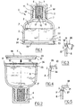
- the device 1 for packaging and application represented at figure 1 has a container 2 of longitudinal axis X whose body 8 defines a first space 3 containing a liquid product P, for example a product for the makeup, care or protection of the body or face. It may be for example a product intended for application to the skin, including the mucous membranes, or the hair.
- a liquid product P for example a product for the makeup, care or protection of the body or face. It may be for example a product intended for application to the skin, including the mucous membranes, or the hair.
- the device 1 also comprises an applicator 4 contained in a second space 5 of the container 2, delimited laterally by a tubular skirt 9 of axis X.
- the applicator 4 is for example made in a compressible foam, in particular with open cells.
- the applicator 4 is in the example shown completely outside the first space 3, even when the device 1 is closed.
- the body 8 is made in one piece by thermoplastic injection molding with the skirt 9 and with a partition 10 separating the first 3 and second 5 spaces.
- the body 8 may be made of a material and / or with a shape, in particular a wall thickness, conferring on it the required rigidity.
- the wall of the body 8 may be, as illustrated, symmetrical of revolution about the longitudinal axis X, and extend axially substantially from the lower end of the device 1 to the partition 10, more than half of the the total height of the device in the example under consideration.
- the skirt 9 is connected in the example shown by a shoulder 7 to the body 8 and forms the neck of the container.
- the body 8 comprises in the lower part 11 an opening 12, as can be seen on the figure 2 in which is fixed a first closure member 20.
- the skirt 9 can be made with, as illustrated, on its outer surface, a thread 13 for fastening by screwing a second closure member 6, the latter comprising for example a surface 14 for sealingly applying on a corresponding surface 15 of the skirt 9, so as to obtain a sealed closure of the container at its upper part.
- the second closure member 6 could comprise other sealing means, in particular an annular lip distinct from the threaded skirt engaging on the thread 13, this lip being sealingly applied to the inner surface of the skirt 9 for example.
- the partition 10 extends, in the illustrated example, substantially perpendicular to the axis X.
- the body 8 of the container is made in one piece in the example of Figures 1 and 2 with a chimney 17 connected at its base to the partition 10 and defining an internal channel 16 of axis X, by which the product contained in the container 2 can win the applicator 4, which makes it possible to establish a permanent fluidic communication between the spaces 3 and 5.
- the first closure member 20 comprises an annular sealing lip 21 which is sealingly applied to the radially inner surface 22 of the lower part 11 of the body 8.
- the height of the lip 21 is example between 3 and 14 mm, for example at least 5 mm.
- the first closure member 20 is for example fixed by snapping on the body 8 and comprises for this purpose a relief such as an annular bead 23 engaged in a corresponding annular groove 24 of the body 8.
- the lower part 11 of the container may comprise a shoulder 25 serving as a stop for the first closure member 20.
- the applicator 4 can be fixed in the space 5, for example by gluing, welding or clamping, or alternatively by means of an additional fastening element, reported for example on the skirt 9, then the second closure member 6 is put in place and the container returned. This can then be filled with the product P as shown in FIG. figure 2 .
- the first closure member 20 can then be snapped onto the body 8.
- the annular sealing lip 21 can be applied to the inner surface 22 of the body 8 before the first closing member 20 has completed its downward stroke, so that an overpressure can be created in the space 3.
- the shape of the closing member 20 may be chosen depending in particular on the volume of air possibly present above the product during the establishment of the closure member, the nature of the product and that of the implementing body.
- the overpressure generated by the reduction of the internal volume of the body during the depression of the first closure member may be for example between 10 and 400 millibar, or between 50 and 350 millibar, or even between 100 and 300 millibar.
- the sealed contact of the first closure member and the body 8 may take place for example while the first closure member moves with a stroke of at least 3 mm.
- the user has an applicator that can have a greater autonomy.
- the container can be returned and for example packaged in a cardboard box, conventionally.
- fixed irremovably it should be understood that the consumer can not normally, without the aid of a tool and without exerting stresses likely to damage the first closure member 20, proceed to the removal of that -this.
- the invention is not limited to a particular mode of attachment of the first closure member 20 to the body 8.
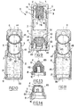
- the first closure member 20 may for example comprise a rim 30 at its periphery, as illustrated in FIG. figure 3 , this flange having on its radially inner surface an annular bead 31 arranged to snap into an annular groove 32 of the body 8 of the container.
- the first closure member 20 may comprise, in this example also, an annular sealing lip 21, as in the embodiment of FIG. figure 1 , this lip 21 being concentric with the rim 30.
- the sealing lip 21 can make it possible to seal on a height of, for example, between 3 and 14 mm, even between 5 and 12 mm, and even between 8 and 10 mm for example.
- the sealed contact can be established at the beginning or during the latching or screwing operation, and until the final fixing. The contact may take place on all or part of the height h of the lip 21.
- the body 8 of the container is made with an annular rib 34 which can engage in a corresponding groove 35 formed on the first closure member 20, the assembly of the latter and the body 8 being performed for example by gluing or welding, especially by ultrasound, after engagement of the rib 34 in the groove 35.
- the latter is, in the example shown, radially edged by the sealing lip 21.
- the assembly of the first closure member 20 and the body 8 can also be performed by welding, the lower portion 11 of the container comprising for example a shoulder 37 against which can bear the first closure member 20 when it is put in place on the body 8.
- This attachment can for example be made by screwing, the first closure member having a threaded outer skirt arranged to be screwed on the lower part 11 of the container, or by snapping.
- the body 8 of the container can be made with a constant inner cross section over substantially its entire height.
- the closure member 20 may comprise a peripheral portion 63 projecting from the body of the container.
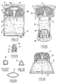
- the first closure member 20 may be made with an outwardly concave outer face, particularly in its central part, as illustrated in FIG. figure 7 .
- the first closure member 20 can also be made with a recess 18, as illustrated in FIG. figure 8 , allowing to receive a flattened element 19 such as for example a label or a mirror.
- the first closure member 20 may also be made with a substantially flat outer face and perpendicular to the X axis in its central region, allowing for example the container to be able to stand vertically on a horizontal flat surface.
- the first closure member 20 is fixed directly on the body of the container, and constitutes the bottom thereof.
- Fixation of the first closure member 20 on the container body can also be done, as illustrated in FIG. figure 9 , via an end piece 31 arranged to attach to the lower part 11 of the body 8 of the container, for example by snapping, welding or gluing and comprising means for fixing the first closure member, by example a skirt 32 threaded externally.
- the end piece 31 may comprise a wall 33, through which openings 34, serve as a seat for a second applicator 35 which can be secured to the first closure member 20.
- this second applicator 35 is made of a foam and the closure member 20 comprises a chimney 36 on which this second applicator 35 is fixed.
- the annular sealing lip 21 is applied to the inner surface of the skirt 32 so that it is created in the space 3, at the During the screwing of the first closure member, an overpressure. If appropriate, the closure member 20 is put in place at the same time as the end piece being pre-mounted thereon.
- the applicator 4 is integral with the container but it is not beyond the scope of the present invention when the applicator 4 is secured to the second closure member 6, as shown in FIG. figure 10 .
- the applicator 4 remains totally outside, in the example described, of the first space 3, when the device 1 is closed.
- the applicator 4 is not dewatered by the partition 10.
- the second space 5 is delimited below by the partition 10, which serves as a seat for the applicator 4 and which has a generally concave shape towards the applicator 4, this partition 10 being traversed by a plurality of orifices 42 allowing spaces 3 and 5 to communicate with each other.
- the applicator 4 is for example fixed to the end of a chimney 44 of the closing member 6, this chimney being surrounded by an outer skirt 45 arranged to be screwed onto the thread 13.
- the first closure member 20 constitutes more than the bottom of the container and has at its periphery an outer skirt 46 which covers at least a portion of the body 8, for example which extends as illustrated over the entire height of the body 8 until at the base of the skirt 9 to dress the container.
- the outer skirt 46 may contribute, if necessary, to the sealing of the container and to generate an overpressure in the container at the time of its introduction.
- the outer skirt 46 may comprise in the upper part a relief, for example an annular bead 47, snapped into a corresponding relief, for example an annular groove 48, of the body 8 of the container.
- the applicator 4 can be made in many ways without departing from the scope of the present invention.
- the applicator 4 when permanently attached to the container, may in particular comprise a chamber 80, as illustrated in FIG. figure 12 in which the chimney 17 opens.
- This chamber 80 may be separated from the outside by a membrane 81 which may or may not be flocked externally and be made of a foam or other porous material.
- the applicator 4 comprises a peripheral groove 82 conferring flexibility to the application.
- the applicator 4 may have an application surface 83 of generally tapered shape, for example frustoconical.
- the thread 13 may not be made on the skirt 9 but on the body 8, for example above a shoulder 84 thereof.
- skirt 9 can be made substantially with the same outside diameter as the body 8, the latter having for example the general shape of a pen.
- the container can be made with various shapes, as will be understood.
- the container has an enlarged head, the applicator 4 having a larger surface area for application than the second applicator 35.
- the container may have a non-symmetrical shape of revolution, for example a polygonal cross-section, in particular a square section as illustrated in FIG. figure 17 or triangular as shown in the figure 18 or a cross section of oblong shape, for example oval, elliptical or lenticular as shown in FIG. figure 19 .
- a non-symmetrical shape of revolution for example a polygonal cross-section, in particular a square section as illustrated in FIG. figure 17 or triangular as shown in the figure 18 or a cross section of oblong shape, for example oval, elliptical or lenticular as shown in FIG. figure 19 .
- the body 8 can be made with a lower part flared downwards, as illustrated in FIG. figure 20 .
- the process according to the invention consisting in creating an overpressure in the container at the time of filling so as to increase the quantity of product of which charge the applicator before the first use can be implemented with a container such as that shown in the figure 21 , in which the applicator 4 is fixed on a support piece 70 which is not made integrally with the body 8 of the container but attached thereto.
Landscapes
- Engineering & Computer Science (AREA)
- Mechanical Engineering (AREA)
- Closures For Containers (AREA)
- Coating Apparatus (AREA)
- Containers And Packaging Bodies Having A Special Means To Remove Contents (AREA)
- Basic Packing Technique (AREA)
- Auxiliary Devices For And Details Of Packaging Control (AREA)
- Packages (AREA)
- Supplying Of Containers To The Packaging Station (AREA)
Claims (38)
- Vorrichtung (1) zur Konditionierung und zur Anwendung eines Produktes, insbesondere eines kosmetischen Produktes, die aufweist:- einen Behälter (2), der aufweist:- einen starren Körper (8) und einen ersten Raum (3) im Inneren des Körpers um einen Vorrat des Produktes (P) aufzunehmen,- einen zweiten Raum (5), der sich von dem ersten unterscheidet,- einer Zwischenwand (10), die zumindest von einer Öffnung durchdrungen ist, die es dem zweiten Raum ermöglicht, in einer permanenten Weise mit dem ersten Raum in Verbindung zu sein,- einem ersten starren Verschlusselement (20) einer Öffnung (12) des ersten Raumes des Körpers (8), das auf dem Körper (8) aufgebaut ist, und verschieden von einem Kolben ist,- einer Appliziereinrichtung (4), die zumindest teilweise in dem zweiten Raum angeordnet ist,- einem zweiten Verschlusselement (6), das in einer Weis konstruiert ist, um sich in einer lösbaren Weise auf dem Behälter zu fixieren, um den zweiten Raum zu schließen,dadurch gekennzeichnet, dass das erste Verschlusselement (20) und der Körper des Behälters in der Weise angeordnet sind, dass die Anordnung des ersten Verschlusselements in dem ersten Raum (3), wobei das zweite Verschlusselements bereits an seinem Platz ist, wobei der erste Raum (3) mit Produkt gefüllt ist und der Behälter zum Entgegengesetzten bzw. seitenverkehrt einen Überdruck erzeugt, der das Produkt (P) dazu zwingt, sich in den zweiten Raum zu ergießen, um die Applikationseinrichtung (4) zu tränken, wobei das erste Verschlusselement ein Abdichtungsorgan aufweist, das selbst dicht ist, das auf einer inneren Oberfläche des Körpers in einer dichtenden Weise anlässlich der Montage des ersten Verschlusselements, angesetzt wird, wenn das erste Verschlussorgan seine definitive bzw. endgültige Position noch nicht erreicht hat.
- Vorrichtung nach Anspruch 1, dadurch gekennzeichnet, dass der Verschluss in einem einzigen Gang mit dem Körper (8) durch Formen von Material verwirklicht wird.
- Vorrichtung nach einem der Ansprüche 1 oder 2, dadurch gekennzeichnet, dass sie eine rohrartige Zylinderfläche (9) bzw. Schürze aufweist, die zumindest teilweise den zweiten Raum begrenzt.
- Vorrichtung nach einem der Ansprüche 1 bis 3, dadurch gekennzeichnet, dass das erste Verschlusselement (20) eine ringförmige Dichtlippe (21) aufweist, die auf einer inneren Fläche des Körpers des Behälters anliegt.
- Vorrichtung nach Anspruch 4, dadurch gekennzeichnet, dass die Dichtlippe (21) ausgebildet ist, anlässlich der Montage des ersten Verschlusselements (20) um in einer dichtenden Weise auf der inneren Fläche des Körpers des Behälters anzulegen, während das erste Verschlussorgan noch nicht seine definitive bzw. endgültige Position erreicht hat.
- Vorrichtung nach einem der Ansprüche 4 und 5, dadurch gekennzeichnet, dass die Dichtlippe eine Höhe von mehr als oder gleich 3 mm oder besser als 5 mm vorweist.
- Vorrichtung nach Anspruch 6, dadurch gekennzeichnet, dass sich die Dichtlippe auf dem Körper in einer dichtenden Weise auf einer Höhe ansetzt, die zwischen 3 und 14 mm liegt.
- Vorrichtung nach Anspruch 1, dadurch gekennzeichnet, dass der Überdruck zwischen 10 und 400 mbar liegt.
- Vorrichtung nach irgendeinem der voranstehenden Ansprüche, dadurch gekennzeichnet, dass das erste Verschlusselement (20) in einer nicht abnehmbaren Weise auf den Körper des Behälters ohne die Möglichkeit einer Versetzung relativ zu dem Körper des Behälters fixiert ist.
- Vorrichtung nach dem voranstehenden Anspruch, dadurch gekennzeichnet, dass das erste Verschlusselement durch Einrasten bzw. Verrasten auf dem Körper des Behälters festgelegt ist.
- Vorrichtung nach Anspruch 9, dadurch gekennzeichnet, dass das erste Verschlusselement durch Verkleben oder durch Verschweißen, insbesondere durch Ultraschall, auf dem Körper des Behälters festgelegt ist.
- Vorrichtung nach irgendeinem der Ansprüche 1 bis 8, dadurch gekennzeichnet, dass das erste Verschlusselement in einer abnehmbaren Weise auf dem Körper des Behälters festgelegt ist.
- Vorrichtung nach dem voranstehenden Anspruch, dadurch gekennzeichnet, dass das erste Verschlusselement (20) durch Verschrauben auf dem Körper des Behälters festgelegt ist.
- Vorrichtung nach Anspruch 1, dadurch gekennzeichnet, dass das erste Verschlusselement (20) einen Unterbringungsraum (18) aufweist, in welchem ein Element (19) aufgenommen ist, wie etwa ein Etikett oder ein Spiegel.
- Vorrichtung nach Anspruch 1, dadurch gekennzeichnet, dass das erste Verschlusselement (20) eine Zylinderfläche bzw. eine Schürze (46) aufweist, die äußerlich zumindest teilweise den Körper des Behälters abdeckt.
- Vorrichtung nach dem voranstehenden Anspruch, dadurch gekennzeichnet, dass die Zylinderfläche bzw. Schürze (46) genau im Inneren des Körpers (8) des Behälters aufgenommen ist.
- Vorrichtung nach Anspruch 1, dadurch gekennzeichnet, dass sie ein Endstück (31) aufweist, das in der Öffnung (12) des Körpers des Behälters aufgebaut ist und einen Unterbringungsraum definiert, in welchem eine zweite Applikationseinrichtung (35) aufgenommen ist.
- Vorrichtung nach dem voranstehenden Ansprüche, dadurch gekennzeichnet, dass das erste Verschlusselement (20) und das Endstück (31) in einer Weise verwirklicht sind, um eine abnehmbare Festlegung des ersten Verschlusselement (20) auf dem Endstück zu erlauben.
- Vorrichtung nach Anspruch 1, dadurch gekennzeichnet, dass das erste Verschlusselement unmittelbar mit dem Körper des Behälters in Kontakt ist.
- Vorrichtung nach einem der voranstehenden Ansprüche, dadurch gekennzeichnet, dass das erste Verschlusselement auf dem Körper des Behälters in einer Weise festgelegt ist, um einen Kontakt zu dem Produkt zu ermöglichen.
- Vorrichtung nach einem der voranstehenden Ansprüche, dadurch gekennzeichnet, dass der Körper des Behälters auf einem Hauptteil seiner Länge einen sich transversal vergrößernden Abschnitt in Annäherung an die Öffnung darstellt.
- Vorrichtung nach irgendeinem der Ansprüche 1 bis 20, dadurch gekennzeichnet, dass der Körper des Behälters über einen Hauptteil seiner Länge einen konstant transversalen Abschnitt aufweist.
- Vorrichtung nach Anspruch 1, dadurch gekennzeichnet, dass das erste Verschlusselement nicht mehr als den Boden des Behälters bildet.
- Vorrichtung nach irgendeinem der voranstehenden Ansprüche, dadurch gekennzeichnet, dass das erste Verschlusselement eine rotationssymmetrische Form darstellt.
- Vorrichtung nach Anspruch 3, dadurch gekennzeichnet, dass die rohrartige Zylinderfläche bzw. Schürze (9) mit mindestens einer Erhebung (13) verwirklicht ist, die die Festlegung des zweiten Verschlusselements (6) erlaubt.
- Vorrichtung nach irgendeinem der voranstehenden Ansprüche, dadurch gekennzeichnet, dass die Applikationseinrichtung (4) aus einem Stück mit dem zweiten Verschlusselement (6) ist.
- Vorrichtung nach dem voranstehenden Anspruch und dem Anspruch 3, dadurch gekennzeichnet, dass das zweite Verschlusselement mit einer äußeren Zylinderfläche bzw. Schürze (45), die angeordnet ist, um sich auf der rohrförmigen Zylinderfläche bzw. Schürze (9) des Behälters festzulegen, und einem inneren Schacht (44) am Ende verwirklicht ist, an welchem die Appliziereinrichtung (4) festgelegt ist.
- Vorrichtung nach einem der Ansprüche 26 und 27, dadurch gekennzeichnet, dass die Zwischenwand (10) als Sitz bzw. Aufnahme der Appliziereinrichtung (4) dient.
- Vorrichtung nach einem der Ansprüche 1 bis 25, dadurch gekennzeichnet, dass die Appliziereinrichtung (4) aus einem Stück mit dem Körper (8) des Behälters ist.
- Vorrichtung nach Anspruch 29, dadurch gekennzeichnet, dass der Körper (8) in einem Schritt mit einem Schacht (17) verwirklicht ist, der auf der Appliziereinrichtung (4) mündet.
- Vorrichtung nach Anspruch 30, dadurch gekennzeichnet, dass der Schacht (17) aus einem einzigen Stück mit der Zwischen- bzw. Trennwand (10) verwirklicht ist.
- Verfahren zur Herstellung einer Vorrichtung zur Konditionierung und zur Applikation eines Produktes, insbesondere jener, die in einem der voranstehenden Ansprüche definiert ist, das die nachfolgenden Schritte aufweist:- in einer Füllstation wird ein Behälter (2) angeordnet, der einen Körper (8) aufweist, der einen ersten Raum (3) definiert, der über eine Öffnung (12) in ein erstes Ende des Körpers mündet, wobei der Behälter eine Appliziereinrichtung (4) unterbringt, die in einem zweiten Raum (5) untergebracht ist, der an einem zweiten Ende des Behälters gegenüber dem ersten vorgesehen ist, wobei die Orientierung des Behälters in der Befüllstation derart ist, dass sich der zweite Raum unter dem ersten befindet,- der erste Raum wird zumindest teilweise mit Produkt über die Öffnung (12) befüllt,- auf dem Körper des Behälters wird ein erstes Verschlusselement (20) aufgebaut, wobei die Platzierung des ersten Verschlusselement auf dem Körper des Behälters von einem Überdruck auf das Innere des Behälters begleitet wird, der Produkt in dem Behälter fortgesetzt in Richtung der Appliziereinrichtung befördert, wobei das erste Verschlusselement ein Abdichtungsorgan aufweist, das selbst dicht ist, das auf einer inneren Oberfläche des Körpers in einer dichtenden Weise anlässlich der Montage des ersten Verschlussorganes, angesetzt wird, wenn das erste Verschlussorgan seine definitive bzw. endgültige Position noch nicht erreicht hat.
- Verfahren nach dem voranstehenden Anspruch, dadurch gekennzeichnet, dass der Körper des Behälters in einem Stück mit einer Trennwand bzw. Zwischenwand (10) verwirklicht wird, die den ersten und den zweiten Raum trennt und zumindest eine Öffnung aufweist, die eine Fluidverbindung zwischen den Räumen ermöglicht.
- Verfahren nach Anspruch 32, dadurch gekennzeichnet, dass der Überdruck zwischen 10 und 400 mbar liegt.
- Verfahren nach einem der Ansprüche 32 bis 34, dadurch gekennzeichnet, dass der erste und zweite Raum permanent miteinander in Verbindung stehen.
- Verfahren nach einem der Ansprüche 31 bis 35, dadurch gekennzeichnet, dass das erste Verschlusselement von einem Kolben verschieden ist.
- Verfahren nach einem der Ansprüche 32 bis 36, dadurch gekennzeichnet, dass das erste Verschlusselement durch Verrastung, Gewinde, Verklebung oder Verschweißung auf dem Körper (8) festgelegt wird.
- Verfahren nach irgendeinem der Ansprüche 32 bis 37, dadurch gekennzeichnet, dass das erste Verschlusselement beim dichtenden Kontakt mit dem Körper über einen Hub von mindestens 3 mm, ja sogar zumindest 5 mm deplatziert ist, um den Überdruck zu erzeugen.
Applications Claiming Priority (2)
| Application Number | Priority Date | Filing Date | Title |
|---|---|---|---|
| FR0311543 | 2003-10-02 | ||
| FR0311543A FR2860496B1 (fr) | 2003-10-02 | 2003-10-02 | Dispositif de conditionnement et d'application d'un produit cosmetique |
Publications (2)
| Publication Number | Publication Date |
|---|---|
| EP1520798A1 EP1520798A1 (de) | 2005-04-06 |
| EP1520798B1 true EP1520798B1 (de) | 2010-02-17 |
Family
ID=34307351
Family Applications (1)
| Application Number | Title | Priority Date | Filing Date |
|---|---|---|---|
| EP04300649A Expired - Lifetime EP1520798B1 (de) | 2003-10-02 | 2004-10-04 | Vorrichtung zur Verpackung und zur Anwendung eines kosmetischen Produkts |
Country Status (6)
| Country | Link |
|---|---|
| US (1) | US7325993B2 (de) |
| EP (1) | EP1520798B1 (de) |
| AT (1) | ATE457934T1 (de) |
| DE (1) | DE602004025538D1 (de) |
| ES (1) | ES2340278T3 (de) |
| FR (1) | FR2860496B1 (de) |
Families Citing this family (18)
| Publication number | Priority date | Publication date | Assignee | Title |
|---|---|---|---|---|
| CA2680749C (en) * | 2007-04-04 | 2016-05-10 | Avon Products, Inc. | Shaper |
| FR2919585B1 (fr) * | 2007-07-30 | 2012-05-04 | Oreal | Dispositif de conditionnement et d'application |
| FR2922806B1 (fr) * | 2007-10-26 | 2009-12-18 | Alcan Packaging Beauty Serv | Procede et dispositif pour fabriquer en grande cadence des corps en matiere plastique dont la surface exterieure est munie d'une etiquette |
| US20090263174A1 (en) * | 2008-03-31 | 2009-10-22 | David Matthew Groh | Package For Dispensing A Personal Care Product |
| CN101980629A (zh) * | 2008-03-31 | 2011-02-23 | 宝洁公司 | 用于使个人护理产品发泡的包装 |
| EP2210519A1 (de) | 2009-01-27 | 2010-07-28 | L'Oréal | Vorrichtung zur Verpackung und Anwendung mit einer vibrierenden Quelle ausgestattet |
| EP2408329B1 (de) * | 2009-03-20 | 2017-11-15 | The Gillette Company LLC | Bürstenkopf zur verwendung auf einem behälter zur abgabe einer zusammensetzung |
| US20110076088A1 (en) * | 2009-09-30 | 2011-03-31 | David Matthew Groh | Package For Dispensing A Personal Care Product |
| US8210187B1 (en) * | 2010-03-25 | 2012-07-03 | Lava Industries, Inc. | Cosmetic powder dispenser |
| US20130067672A1 (en) * | 2011-09-16 | 2013-03-21 | Joanna Paulina Kozlowski | In shower make-up remover |
| US8967896B2 (en) | 2011-11-23 | 2015-03-03 | Dean Johnson | Cosmetic apparatus and method |
| US8899859B2 (en) * | 2011-12-16 | 2014-12-02 | Carefusion 2200, Inc. | Antiseptic applicator |
| US8376134B1 (en) * | 2012-05-18 | 2013-02-19 | Philip Andrew Underwood | Drink bottle with multiple drink dosage device |
| ES2549694B9 (es) * | 2014-10-23 | 2017-01-04 | Grifols, S.A. | Procedimiento de llenado aséptico de una bolsa |
| ITUA20161903A1 (it) * | 2016-03-22 | 2017-09-22 | Aroma System Srl | Capsula per ottenere bevande e metodo di produzione della stessa |
| FR3061065B1 (fr) | 2016-12-23 | 2021-05-07 | Dior Christian Parfums | Procede de fabrication d'un organe d'application de produit cosmetique liquide, organe d'application et applicateur |
| CN110602964A (zh) * | 2017-02-17 | 2019-12-20 | 珀雷克斯公司 | 液体涂敷器和装置 |
| US20220378171A1 (en) * | 2021-05-27 | 2022-12-01 | L'oreal | Applicator having three-dimensional surface contact with reservoir |
Family Cites Families (18)
| Publication number | Priority date | Publication date | Assignee | Title |
|---|---|---|---|---|
| CH185011A (de) * | 1935-05-31 | 1936-06-30 | Strassel Eugen | Vorrichtung an Behältern, insbesondere Tuben, zum Schutze derselben. |
| FR1142591A (fr) * | 1956-02-08 | 1957-09-19 | Appareil à réservoir et piston, alimenté par gravitation et par pression, pour application de liquide par contact | |
| US3264676A (en) * | 1964-04-02 | 1966-08-09 | Schwartzman Gilbert | Spin welded package |
| US4548524A (en) * | 1982-07-22 | 1985-10-22 | Calumet Manufacturing Co. | Dispensing package with applicator surface |
| FR2588457B1 (fr) * | 1985-10-11 | 1987-12-11 | Chen Teng Mo | Dispositif perfectionne de tampon pour demaquillage |
| FR2789660B1 (fr) * | 1999-02-16 | 2001-05-04 | Oreal | Ensemble de conditionnement et d'application a applicateur auto alimente |
| ATE226150T1 (de) * | 1999-04-17 | 2002-11-15 | Faber Castell Ag | Auftragsgerät |
| FR2798646B1 (fr) | 1999-09-21 | 2001-12-28 | Oreal | Dispositif de conditionnement et d'application |
| FR2800041B1 (fr) | 1999-10-22 | 2001-12-07 | Oreal | Ensemble de conditionnement et d'application d'un produit liquide |
| FR2804846B1 (fr) * | 2000-02-16 | 2002-08-09 | Oreal | Dispositif de conditionnement et d'application comportant une structure poreuse incorporant un agent biocide |
| US20020004848A1 (en) * | 2000-03-29 | 2002-01-10 | Krishna Sudarshan | System and method of providing an asynchronous interface between a client system and an enterprise javabeans-enabled server |
| WO2002005445A1 (en) * | 2000-07-08 | 2002-01-17 | Samsung Electronics Co., Ltd. | Method and apparatus for flexible data rate matching by symbol insertion for a data communication system |
| FR2812276B1 (fr) * | 2000-07-27 | 2003-01-10 | Oreal | Dispositif pour le conditionnement et l'application d'un produit, notamment cosmetique |
| FR2812277B1 (fr) | 2000-07-27 | 2003-01-10 | Oreal | Dispositif pour le conditionnement et l'application d'un produit, notamment cosmetique |
| FR2814651B1 (fr) * | 2000-10-03 | 2003-08-15 | Oreal | Dispositif de conditionnement et d'application comportant un element d'application compressible servant a l' application du produit et un logement pour recevoir l' element d'application charge en produit |
| FR2823726B1 (fr) * | 2001-04-20 | 2003-06-27 | Oreal | Ensemble pour le conditionnement et l'application d'un produit notamment cosmetique ou de soin |
| FR2830848B1 (fr) * | 2001-10-17 | 2004-07-16 | Oreal | Dispositif d'application d'un produit notamment cosmetique avec un organe d'application amovible |
| FR2832297B1 (fr) | 2001-11-19 | 2004-08-06 | Oreal | Ensemble de conditionnement et d'application d'un produit |
-
2003
- 2003-10-02 FR FR0311543A patent/FR2860496B1/fr not_active Expired - Fee Related
-
2004
- 2004-10-04 ES ES04300649T patent/ES2340278T3/es not_active Expired - Lifetime
- 2004-10-04 DE DE602004025538T patent/DE602004025538D1/de not_active Expired - Lifetime
- 2004-10-04 AT AT04300649T patent/ATE457934T1/de not_active IP Right Cessation
- 2004-10-04 EP EP04300649A patent/EP1520798B1/de not_active Expired - Lifetime
- 2004-10-04 US US10/956,137 patent/US7325993B2/en not_active Expired - Fee Related
Also Published As
| Publication number | Publication date |
|---|---|
| ATE457934T1 (de) | 2010-03-15 |
| EP1520798A1 (de) | 2005-04-06 |
| FR2860496A1 (fr) | 2005-04-08 |
| ES2340278T3 (es) | 2010-06-01 |
| US7325993B2 (en) | 2008-02-05 |
| US20050102978A1 (en) | 2005-05-19 |
| DE602004025538D1 (de) | 2010-04-01 |
| FR2860496B1 (fr) | 2006-06-23 |
Similar Documents
| Publication | Publication Date | Title |
|---|---|---|
| EP1520798B1 (de) | Vorrichtung zur Verpackung und zur Anwendung eines kosmetischen Produkts | |
| EP1820417B1 (de) | Vorrichtung zur Verpackung und Anwendung | |
| EP1029799B1 (de) | Behälter mit Auftragselement zur Aufnahme und Ausgabe einer Flüssigkeit | |
| EP1514492B1 (de) | Vorrichtung zum Aufbewahren und Ausgeben eines kosmetischen Produktes | |
| EP1293448B1 (de) | Behälter und Spender für Kosmetika | |
| EP1205400B1 (de) | Behälter mit Steigrohr und Auftragevorrichtung | |
| CA2262135C (fr) | Ensemble de conditionnement et de distribution d'un produit liquide | |
| EP1020135B1 (de) | Spender mit automatisch gespeister Auftragsvorrichtung | |
| CA2405042C (fr) | Dispositif de conditionnement d'un produit liquide ou en poudre | |
| EP1125517B1 (de) | Vorrichtung zum Aufbewahren und Auftragen mit einem Zwischenspeicher | |
| EP0649795A2 (de) | Ausgabevorrichtung, versehen mit einem Rückschlagventil | |
| EP1524199B1 (de) | Vorrichtung zum Aufbewahren und Anwenden | |
| EP1174190A1 (de) | Aufbewahrungs- und Spendevorrichtung zur Abgabe einer einstellbaren Dosierung | |
| EP1588775A1 (de) | Verpackungs- und Abgabeeinheit eines Produktes, insbesondere eines kosmetischen Produktes | |
| EP2551215A1 (de) | Herstellungsverfahren einer Wiederaufladevorrichtung für wiederaufladbares Spendergehäuse, und entsprechend angepasste Wiederaufladevorrichtung | |
| FR2919585A1 (fr) | Dispositif de conditionnement et d'application | |
| FR2811639A1 (fr) | Dispositif pour le conditionnement et la distribution d'un produit, notamment un produit capillaire | |
| EP2934764A1 (de) | Flüssigkeitsspender | |
| EP1538101A1 (de) | Vorrichtung zum Aufbewahren und zum Auftragen eines Produktes | |
| EP1702531B1 (de) | Vorrichtung zum Aufbewahren und Auftragen eines Kosmetikproduktes | |
| EP1621102B1 (de) | Vorrichtung zum Aufbewahren und Auftragen | |
| FR2799740A1 (fr) | Emballage distributeur a applicateur rotatif | |
| EP4685104A1 (de) | Schnittstelle zum füllen einer flasche mit flüssigkeit und system mit solch einer schnittstelle | |
| BE566802A (de) | ||
| FR2956569A1 (fr) | Dispositif de conditionnement et d'application. |
Legal Events
| Date | Code | Title | Description |
|---|---|---|---|
| PUAI | Public reference made under article 153(3) epc to a published international application that has entered the european phase |
Free format text: ORIGINAL CODE: 0009012 |
|
| 17P | Request for examination filed |
Effective date: 20041004 |
|
| AK | Designated contracting states |
Kind code of ref document: A1 Designated state(s): AT BE BG CH CY CZ DE DK EE ES FI FR GB GR HU IE IT LI LU MC NL PL PT RO SE SI SK TR |
|
| AX | Request for extension of the european patent |
Extension state: AL HR LT LV MK |
|
| AKX | Designation fees paid |
Designated state(s): AT BE BG CH CY CZ DE DK EE ES FI FR GB GR HU IE IT LI LU MC NL PL PT RO SE SI SK TR |
|
| 17Q | First examination report despatched |
Effective date: 20080423 |
|
| GRAP | Despatch of communication of intention to grant a patent |
Free format text: ORIGINAL CODE: EPIDOSNIGR1 |
|
| RIN1 | Information on inventor provided before grant (corrected) |
Inventor name: GUERET, JEAN-LOUIS |
|
| GRAS | Grant fee paid |
Free format text: ORIGINAL CODE: EPIDOSNIGR3 |
|
| GRAA | (expected) grant |
Free format text: ORIGINAL CODE: 0009210 |
|
| AK | Designated contracting states |
Kind code of ref document: B1 Designated state(s): AT BE BG CH CY CZ DE DK EE ES FI FR GB GR HU IE IT LI LU MC NL PL PT RO SE SI SK TR |
|
| REG | Reference to a national code |
Ref country code: GB Ref legal event code: FG4D Free format text: NOT ENGLISH |
|
| REG | Reference to a national code |
Ref country code: CH Ref legal event code: EP |
|
| REG | Reference to a national code |
Ref country code: IE Ref legal event code: FG4D Free format text: LANGUAGE OF EP DOCUMENT: FRENCH |
|
| REF | Corresponds to: |
Ref document number: 602004025538 Country of ref document: DE Date of ref document: 20100401 Kind code of ref document: P |
|
| REG | Reference to a national code |
Ref country code: ES Ref legal event code: FG2A Ref document number: 2340278 Country of ref document: ES Kind code of ref document: T3 |
|
| REG | Reference to a national code |
Ref country code: NL Ref legal event code: VDEP Effective date: 20100217 |
|
| PG25 | Lapsed in a contracting state [announced via postgrant information from national office to epo] |
Ref country code: PT Free format text: LAPSE BECAUSE OF FAILURE TO SUBMIT A TRANSLATION OF THE DESCRIPTION OR TO PAY THE FEE WITHIN THE PRESCRIBED TIME-LIMIT Effective date: 20100617 |
|
| PG25 | Lapsed in a contracting state [announced via postgrant information from national office to epo] |
Ref country code: FI Free format text: LAPSE BECAUSE OF FAILURE TO SUBMIT A TRANSLATION OF THE DESCRIPTION OR TO PAY THE FEE WITHIN THE PRESCRIBED TIME-LIMIT Effective date: 20100217 Ref country code: AT Free format text: LAPSE BECAUSE OF FAILURE TO SUBMIT A TRANSLATION OF THE DESCRIPTION OR TO PAY THE FEE WITHIN THE PRESCRIBED TIME-LIMIT Effective date: 20100217 Ref country code: SI Free format text: LAPSE BECAUSE OF FAILURE TO SUBMIT A TRANSLATION OF THE DESCRIPTION OR TO PAY THE FEE WITHIN THE PRESCRIBED TIME-LIMIT Effective date: 20100217 Ref country code: PL Free format text: LAPSE BECAUSE OF FAILURE TO SUBMIT A TRANSLATION OF THE DESCRIPTION OR TO PAY THE FEE WITHIN THE PRESCRIBED TIME-LIMIT Effective date: 20100217 |
|
| REG | Reference to a national code |
Ref country code: IE Ref legal event code: FD4D |
|
| PG25 | Lapsed in a contracting state [announced via postgrant information from national office to epo] |
Ref country code: EE Free format text: LAPSE BECAUSE OF FAILURE TO SUBMIT A TRANSLATION OF THE DESCRIPTION OR TO PAY THE FEE WITHIN THE PRESCRIBED TIME-LIMIT Effective date: 20100217 Ref country code: SE Free format text: LAPSE BECAUSE OF FAILURE TO SUBMIT A TRANSLATION OF THE DESCRIPTION OR TO PAY THE FEE WITHIN THE PRESCRIBED TIME-LIMIT Effective date: 20100217 Ref country code: RO Free format text: LAPSE BECAUSE OF FAILURE TO SUBMIT A TRANSLATION OF THE DESCRIPTION OR TO PAY THE FEE WITHIN THE PRESCRIBED TIME-LIMIT Effective date: 20100217 Ref country code: NL Free format text: LAPSE BECAUSE OF FAILURE TO SUBMIT A TRANSLATION OF THE DESCRIPTION OR TO PAY THE FEE WITHIN THE PRESCRIBED TIME-LIMIT Effective date: 20100217 Ref country code: IE Free format text: LAPSE BECAUSE OF FAILURE TO SUBMIT A TRANSLATION OF THE DESCRIPTION OR TO PAY THE FEE WITHIN THE PRESCRIBED TIME-LIMIT Effective date: 20100217 Ref country code: GR Free format text: LAPSE BECAUSE OF FAILURE TO SUBMIT A TRANSLATION OF THE DESCRIPTION OR TO PAY THE FEE WITHIN THE PRESCRIBED TIME-LIMIT Effective date: 20100518 Ref country code: CY Free format text: LAPSE BECAUSE OF FAILURE TO SUBMIT A TRANSLATION OF THE DESCRIPTION OR TO PAY THE FEE WITHIN THE PRESCRIBED TIME-LIMIT Effective date: 20100217 |
|
| PG25 | Lapsed in a contracting state [announced via postgrant information from national office to epo] |
Ref country code: BG Free format text: LAPSE BECAUSE OF FAILURE TO SUBMIT A TRANSLATION OF THE DESCRIPTION OR TO PAY THE FEE WITHIN THE PRESCRIBED TIME-LIMIT Effective date: 20100517 Ref country code: CZ Free format text: LAPSE BECAUSE OF FAILURE TO SUBMIT A TRANSLATION OF THE DESCRIPTION OR TO PAY THE FEE WITHIN THE PRESCRIBED TIME-LIMIT Effective date: 20100217 Ref country code: SK Free format text: LAPSE BECAUSE OF FAILURE TO SUBMIT A TRANSLATION OF THE DESCRIPTION OR TO PAY THE FEE WITHIN THE PRESCRIBED TIME-LIMIT Effective date: 20100217 |
|
| PLBE | No opposition filed within time limit |
Free format text: ORIGINAL CODE: 0009261 |
|
| STAA | Information on the status of an ep patent application or granted ep patent |
Free format text: STATUS: NO OPPOSITION FILED WITHIN TIME LIMIT |
|
| 26N | No opposition filed |
Effective date: 20101118 |
|
| PG25 | Lapsed in a contracting state [announced via postgrant information from national office to epo] |
Ref country code: DK Free format text: LAPSE BECAUSE OF FAILURE TO SUBMIT A TRANSLATION OF THE DESCRIPTION OR TO PAY THE FEE WITHIN THE PRESCRIBED TIME-LIMIT Effective date: 20100217 |
|
| BERE | Be: lapsed |
Owner name: L'OREAL Effective date: 20101031 |
|
| PG25 | Lapsed in a contracting state [announced via postgrant information from national office to epo] |
Ref country code: MC Free format text: LAPSE BECAUSE OF NON-PAYMENT OF DUE FEES Effective date: 20101031 |
|
| REG | Reference to a national code |
Ref country code: CH Ref legal event code: PL |
|
| PG25 | Lapsed in a contracting state [announced via postgrant information from national office to epo] |
Ref country code: LI Free format text: LAPSE BECAUSE OF NON-PAYMENT OF DUE FEES Effective date: 20101031 Ref country code: CH Free format text: LAPSE BECAUSE OF NON-PAYMENT OF DUE FEES Effective date: 20101031 |
|
| PG25 | Lapsed in a contracting state [announced via postgrant information from national office to epo] |
Ref country code: BE Free format text: LAPSE BECAUSE OF NON-PAYMENT OF DUE FEES Effective date: 20101031 |
|
| PG25 | Lapsed in a contracting state [announced via postgrant information from national office to epo] |
Ref country code: HU Free format text: LAPSE BECAUSE OF FAILURE TO SUBMIT A TRANSLATION OF THE DESCRIPTION OR TO PAY THE FEE WITHIN THE PRESCRIBED TIME-LIMIT Effective date: 20100818 Ref country code: LU Free format text: LAPSE BECAUSE OF NON-PAYMENT OF DUE FEES Effective date: 20101004 |
|
| PG25 | Lapsed in a contracting state [announced via postgrant information from national office to epo] |
Ref country code: TR Free format text: LAPSE BECAUSE OF FAILURE TO SUBMIT A TRANSLATION OF THE DESCRIPTION OR TO PAY THE FEE WITHIN THE PRESCRIBED TIME-LIMIT Effective date: 20100217 |
|
| PGFP | Annual fee paid to national office [announced via postgrant information from national office to epo] |
Ref country code: DE Payment date: 20120927 Year of fee payment: 9 Ref country code: FR Payment date: 20121018 Year of fee payment: 9 |
|
| PGFP | Annual fee paid to national office [announced via postgrant information from national office to epo] |
Ref country code: ES Payment date: 20121031 Year of fee payment: 9 Ref country code: IT Payment date: 20121012 Year of fee payment: 9 Ref country code: GB Payment date: 20121003 Year of fee payment: 9 |
|
| GBPC | Gb: european patent ceased through non-payment of renewal fee |
Effective date: 20131004 |
|
| PG25 | Lapsed in a contracting state [announced via postgrant information from national office to epo] |
Ref country code: GB Free format text: LAPSE BECAUSE OF NON-PAYMENT OF DUE FEES Effective date: 20131004 |
|
| REG | Reference to a national code |
Ref country code: FR Ref legal event code: ST Effective date: 20140630 |
|
| REG | Reference to a national code |
Ref country code: DE Ref legal event code: R119 Ref document number: 602004025538 Country of ref document: DE Effective date: 20140501 |
|
| PG25 | Lapsed in a contracting state [announced via postgrant information from national office to epo] |
Ref country code: DE Free format text: LAPSE BECAUSE OF NON-PAYMENT OF DUE FEES Effective date: 20140501 Ref country code: IT Free format text: LAPSE BECAUSE OF NON-PAYMENT OF DUE FEES Effective date: 20131004 Ref country code: FR Free format text: LAPSE BECAUSE OF NON-PAYMENT OF DUE FEES Effective date: 20131031 |
|
| REG | Reference to a national code |
Ref country code: ES Ref legal event code: FD2A Effective date: 20141107 |
|
| PG25 | Lapsed in a contracting state [announced via postgrant information from national office to epo] |
Ref country code: ES Free format text: LAPSE BECAUSE OF NON-PAYMENT OF DUE FEES Effective date: 20131005 |