EP1587177A1 - Kabelklemme - Google Patents
Kabelklemme Download PDFInfo
- Publication number
- EP1587177A1 EP1587177A1 EP05001952A EP05001952A EP1587177A1 EP 1587177 A1 EP1587177 A1 EP 1587177A1 EP 05001952 A EP05001952 A EP 05001952A EP 05001952 A EP05001952 A EP 05001952A EP 1587177 A1 EP1587177 A1 EP 1587177A1
- Authority
- EP
- European Patent Office
- Prior art keywords
- cable
- clamping
- cables
- clamp according
- terminal
- Prior art date
- Legal status (The legal status is an assumption and is not a legal conclusion. Google has not performed a legal analysis and makes no representation as to the accuracy of the status listed.)
- Granted
Links
- 230000002093 peripheral effect Effects 0.000 claims description 10
- 238000009825 accumulation Methods 0.000 claims description 6
- 239000000463 material Substances 0.000 claims description 6
- 229910052736 halogen Inorganic materials 0.000 claims description 5
- 150000002367 halogens Chemical class 0.000 claims description 5
- 238000003825 pressing Methods 0.000 description 9
- 239000000243 solution Substances 0.000 description 5
- 238000010276 construction Methods 0.000 description 3
- 230000000694 effects Effects 0.000 description 3
- 230000001419 dependent effect Effects 0.000 description 1
- 238000010586 diagram Methods 0.000 description 1
- 230000005489 elastic deformation Effects 0.000 description 1
- 238000005516 engineering process Methods 0.000 description 1
- 238000001746 injection moulding Methods 0.000 description 1
- 230000003014 reinforcing effect Effects 0.000 description 1
Images



Classifications
-
- H—ELECTRICITY
- H01—ELECTRIC ELEMENTS
- H01R—ELECTRICALLY-CONDUCTIVE CONNECTIONS; STRUCTURAL ASSOCIATIONS OF A PLURALITY OF MUTUALLY-INSULATED ELECTRICAL CONNECTING ELEMENTS; COUPLING DEVICES; CURRENT COLLECTORS
- H01R13/00—Details of coupling devices of the kinds covered by groups H01R12/70 or H01R24/00 - H01R33/00
- H01R13/58—Means for relieving strain on wire connection, e.g. cord grip, for avoiding loosening of connections between wires and terminals within a coupling device terminating a cable
- H01R13/595—Bolts operating in a direction transverse to the cable or wire
-
- H—ELECTRICITY
- H01—ELECTRIC ELEMENTS
- H01R—ELECTRICALLY-CONDUCTIVE CONNECTIONS; STRUCTURAL ASSOCIATIONS OF A PLURALITY OF MUTUALLY-INSULATED ELECTRICAL CONNECTING ELEMENTS; COUPLING DEVICES; CURRENT COLLECTORS
- H01R13/00—Details of coupling devices of the kinds covered by groups H01R12/70 or H01R24/00 - H01R33/00
- H01R13/58—Means for relieving strain on wire connection, e.g. cord grip, for avoiding loosening of connections between wires and terminals within a coupling device terminating a cable
- H01R13/5804—Means for relieving strain on wire connection, e.g. cord grip, for avoiding loosening of connections between wires and terminals within a coupling device terminating a cable comprising a separate cable clamping part
Definitions
- the invention relates to a cable clamp for at least three cables according to the preamble of claim 1.
- Such cable clamps are used for example in electronic ballasts (ECG) used for lamps.
- ECG electronic ballasts
- OSRAM Distributed ECG of the type Halotronic HTM 105 is a cable clamp with Strain relief integrated, with the two cables, such as a mains voltage supply line and a secondary line for connecting a halogen incandescent lamp can be clamped (see www.osram.de).
- Terminal shell receptacles formed the outer circumference of the two, sections of the same outer diameter cable embrace.
- the clamping force is applied via a clamping screw, with screwed the terminal upper part and the terminal lower part together become.
- the object of the invention is therefore to provide a cable clamp, the one allows reliable clamping of at least three cables.
- the cable clamp is for clamping at least three Cables run asymmetrically, with two of the cables to a cable pair are summarized and a connecting means, such as a Clamping screw between the cable pair and the third cable arranged is.
- a connecting means such as a Clamping screw between the cable pair and the third cable arranged.
- the clamping pressures acting on the pair of cables are particularly suitable apply evenly when concave on the lower part of the clamp Recordings for supporting the cables and on the terminal shell at least a projection is formed, the contact surfaces of the cable pair are set obliquely to each other, so that the cable pair in the associated Cable pair recordings is pressed. That is, the on the cable pair acting forces are symmetrically introduced so that eventually occurring Cancel out lateral forces.
- the projection convex to the cable pair is bulged towards and on mutually facing outer peripheral portions the cable of the cable pair attacks.
- the contact surface of the third cable assigned Forming the upper clamping shell flat and in the horizontal direction For example, the terminal shell may be in the transverse direction with respect to the third cable Align so that any lateral forces may occur due to lateral contact can be supported on the terminal base. It is a prerequisite that the terminal lower part the terminal upper part in the transverse direction embraces.
- the geometry of the contact surfaces of the terminal shell and the receptacles of the terminal lower part is selected and with respect to the axis of the clamping screw arranged such that the clamping pressures acting on each cable have approximately the same size.
- This is the construction preferably designed so that the ratio of the sum the pressing surfaces (receptacles, contact surfaces) for the third cable to the Total pressing surface of the cable pair approximately inversely proportional to the ratio the center distances of the third cable and the cable pair of the Axis of the locking means (clamping screw) behaves.
- the mean center distance of the cable pair from the clamping screw is greater than the axial distance of the third cable, the Pressing area of the cable pair reduced accordingly or the pressing surface
- the third cable can be increased accordingly to the clamping pressures to equalize.
- the contact surfaces for the cables in the terminal shell and the receptacles in the terminal base for each cable by spaced clamping ribs formed, wherein the third cable more clamping ribs than the cables associated with the cable pair.
- the clamping effect can be further improved if the clamping ribs obliquely to the axis of the cables are employed.
- the inclusion in the terminal base is preferably designed so that the two cables of the cable pair abut each other in the clamped state.
- the above-described cable clamp can be particularly advantageous in a use electronic ballast for halogen bulbs.
- this application is not limited to the lamp technology but in principle applicable to any electrical consumers in which strain-relieved cables are used.
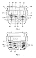
- Figure 1 shows a schematic sectional view of a cable clamp 1 for three cables 2, 3 and 4.
- a cable clamp for example, in The housing of an electronic ballast for halogen bulbs be integrated, the cable 4, for example, a mains voltage supply line and the two cables 2, 3 secondary cables for the connection of two halogen bulbs can be.
- the cable clamp 1 has a housing-shaped Clamping base 8 and a lid-shaped terminal shell 10, by means of an asymmetrically arranged clamping screw 12 with each other are connected. This is in the illustration of Figure 1 only indicated by dash-dotted lines.
- the terms "upper” and “lower part” are not strictly geometrically interpreted but they generally stand for a shared Housing body.
- the terminal base 8 and the terminal shell 10 define a receiving space 14, in which the three cables 2, 3, 4 added in sections are.
- the terminal base 8 and the terminal shell 10 To apply the required for the terminals and the strain relief Clamping force are at the two facing each other inner surfaces the terminal base 8 and the terminal shell 10 to each other spaced clamping ribs 16 and 18 are formed.
- the section according to FIG 1 extends through one of the clamping ribs 16 of the terminal shell 10 and one of the clamping ribs 18 of the clamping base 8.
- the clamping ribs 18 of the Clamping base 8 three concave seats 20, 22, 24, whose Radius of curvature about the outer radius of the cable 2, 3, 4 corresponds.
- the two cables 2, 3 associated recesses 20, 22 are close to each other, so that the cables 2, 3 with their adjacent peripheral surfaces in the clamped state abut each other.
- the one between the two recesses 20, 22 remaining web 26 is held relatively flat and extends in the illustrated embodiment only by about one millimeter across the valley of the recesses 20, 22, while the peripheral edges the recess 24 of the cable 4 and the outer peripheral edges the recesses 20, 22 for the cables 2, 3 further upwards (toward the Terminal upper part 10) are pulled.
- the clamping ribs 16 of the lid-shaped clamp upper part 10 are in the range of the single cable 4 with a horizontal flat contact surface 28 executed while contact surfaces 30, 32 to the cable pair 2, 3 are formed by a convex projection 34 of the clamping ribs 16.
- This convexly curved projection 34 is symmetrical to the vertical in Figure 1 extending dividing plane between the two cables 2, 3 arranged and thus has its deepest area approximately in the area between the two Cables 2, 3. Accordingly, the contact surfaces 30, 32 obliquely to each other employed, so that the clamping forces - as shown in Figure 1 - obliquely and are introduced symmetrically to each other in the cable pair 2, 3, while acting on the cable 4 clamping force acting in the vertical direction.
- the oblique extending contact surfaces 30, 32 and the horizontal bearing surface 28 are designed so that the terminal shell 10 in the horizontal position on the cables 2, 3, 4 rests.
- the centering of the terminal shell 10 with respect to the terminal base 8 takes place essentially on the Contact surfaces 30, 32 of the projection 34 - of the clamping screw 12 must practically no or negligible transverse forces are applied, because the lateral force components of the two indicated clamping forces cancel each other out.
- the force relationships are in the schematic representation according to FIG. 2 clarified.
- dashed lines a clamping rib 16 of the terminal shell 10 is shown.
- the function of the clamping ribs 16 can be with that a lever 36, the one around the axis of the screw plug 12 crossing axis is pivotable.
- the right in Figure 2 leg 38 of Lever 36 is located over the contact surface 28 in the horizontal direction on the cable 4, while the left lever arm over the contact surfaces 30, 32 of the dashed line indicated projection 34 on the cables 2, 3 is applied.
- the resulting Clamping forces F2 and F3 are perpendicular to the surface normal the contact surfaces 30, 32 and intersect at the point Z, the Length a of the lever arm 40 is determined.
- the force acting on the cable 4 clamping force F1 is perpendicular to the lever arm 38, whose length in Figure 2 with b is marked.
- FIG. 3 shows three sections through a cable clamp 1 according to FIG.
- the effective clamping surface is with the cables 2, 3 of the cable pair in each case substantially smaller than with Cable 4, to compensate for the pressures.
- This will be at the illustrated embodiments achieved in that not every one of Ridges on the outer circumference of the cable 2 and 3 attacks.
- In the illustrated Embodiments is about every second clamping rib 16 and 18 on Outer circumference of the cable 2, 3 at.
- the outside Cable 2 associated clamping ribs 16, 18 of the upper clamp part 10 or the clamp base 8 turn on a circumferential circle and thus engage diametrically opposed to each other while, on the contrary, the cable 3 (Section B-B) engaging clamping ribs 16, 18 offset in the axial direction to each other are arranged and thus attack alternately on the cable 3. That is, the cable 3, for example, by two each side by side lying clamping ribs 18 of the clamp base 8 supported while the corresponding clamping rib 16 of the clamp upper part 10 centrally between the two adjacent clamping ribs 18 attacks. This will be the on the cable 3 effective clamping pressure against the on the cable.
- FIG. 4 shows a plan view of the terminal lower part 8. Visible, noticeable is the approximately rectangular in plan view receiving space 14, the side is bounded by the peripheral walls 27 and the non-illustrated Terminal shell 10 is closed.
- the peripheral walls 27 are in the illustrated embodiment with a plurality of side by side lying, groove-shaped recesses 44 which provide a Provide elasticity.
- the upper end of the cable clamp 1 in FIG is formed via an adapter piece 46 projecting from an end face, in a corresponding groove of the housing (not shown) of the electronic ballast engages, so that through the cable clamp 1 practically a frontal conclusion of the ECG housing is formed.
- the protruding from the adapter piece 46 Pins 48 are used for positional positioning with reference to the ECG housing.
- a bottom surface 51 of the clamp base 8 On a bottom surface 51 of the clamp base 8 are a plurality of in Transversely extending clamping ribs 18 are formed according to are formed in the illustration in Figure 1, wherein the receptacles 20, 22 and 24 each shown blackened. That is, the cables 2, 3 used and 4 lie along the blackened areas in the vertical direction (view According to Fig. 4) extending on the spaced apart by the Ridges formed recordings 20, 22 and 24, respectively.
- These clamping ribs 18 are stiffened by additional reinforcing ribs 50, preferably parallel to the cables 2, 3, 4 and thus extend transversely to the clamping ribs 18.
- the construction of the terminal shell 10 is designed accordingly, However, wherein the relative arrangement of the clamping ribs in the upper terminal part 10th and may be chosen differently in the terminal base 8. Between Receivers 22, 24 is provided a hub-shaped material accumulation 52, which is penetrated by the clamping screw 12.
- FIG. 5 shows a variant in which the clamping ribs 18 are not all transverse to the longitudinal axis of the cables 2, 3, 4 but at least some Clamping ribs 18 a are made obliquely to the cable axis, so that the Clamping effect is improved.
- the branches branch Clamping ribs 18, 18 a and then are in the region of material accumulation 52nd brought back together.
- Another special feature is that the Clamping ribs 18, 18a open into the material accumulation 52 in the radial direction.
- Such a construction with branching and radially in the Material accumulation 52 opening clamping ribs 18, 18a is by injection molding much easier to produce than the solution described above according to FIG. 4.
- the superior function of the cable clamp 1 according to the invention is particularly evident when, instead of the intended three cables 2, 3, 4, only two cables - for example the mains voltage supply line 4 and one of the secondary lines 2, 3 are clamped. It is assumed that according to the figures, the mains voltage supply line 4 is arranged on the individual position (to the right of the clamping screw 12), while, for example, the secondary line 2 is inserted into the receptacle 20 and the receptacle 22 remains free (FIG. 6). In this case, when tightening the clamping screw 12, the cable 2 is acted upon by the contact surface 30 with the oblique clamping force F2 and thus pressed into the recess 20. The clamping force F1 extends in the vertical direction.
- the upper clamp part 10 is shifted in the illustration of Figure 6 to the right, so that this transverse force F2 Q is caught by the right in Figure 6 peripheral wall 27 and thus the Terminal upper part 10 defined with respect to the clamping base 8 is positioned in position.
- This shift of the terminal shell 10 to the right is made possible by the fact that the contact surface 28 for the cable 4 extends in the horizontal direction and that the clamping screw receives no transverse forces.
- a corresponding self-centering of the clamp upper part 10 also takes place when the cable 2 is inserted into the receptacle 22 (see FIG. 7).
- the clamp upper component 10 is displaced to the left by the transverse force component F3 Q , until it rests against the left circumferential wall 27 of the clamp base 8.
- the clamping ribs 16, 18 can also be ensured in this case, in addition, that acting on the two cables 2, 4 and 3, 4 clamping pressure is about the same size.
- a cable clamp for at least three cables, with a terminal base and a terminal shell, which together form a receiving space for the cable limit and connectable by means of a clamping screw are.
- two of the cables are combined to form a pair of cables, with the only clamping screw between the cable pair and extending through the third cable.
Landscapes
- Details Of Connecting Devices For Male And Female Coupling (AREA)
- Installation Of Indoor Wiring (AREA)
- Connections Arranged To Contact A Plurality Of Conductors (AREA)
Abstract
Description
- Figur 1
- einen Schnitt durch eine Kabelklemme für drei Kabel;
- Figur 2
- ein Funktionsschaubild der Kabelklemme aus Figur 1 zur Verdeutlichung der wirkenden Kräfte;
- Figur 3
- Schnittdarstellungen der Kabelklemme aus Figur 1;
- Figur 4
- eine Draufsicht auf ein Klemmenunterteil der Kabelklemme aus Figur 1;
- Figur 5
- ein weiteres Ausführungsbeispiel eines Klemmenunterteils und
- Figuren 6, 7
- die Kabelklemme aus Figur 1 mit zwei in unterschiedlichen Positionen geklemmten Kabeln.
Claims (14)
- Kabelklemme für zumindest drei Kabel (2, 3, 4) zur Versorgung eines elektrischen Verbrauchers, insbesondere eines elektronischen Vorschaltgeräts für eine Lampe, mit einem Klemmenunterteil (8) und einem Klemmenoberteil (10), die mittels eines Verbindungsmittels, vorzugsweise einer Klemmschraube (12) miteinander verbindbar sind, um die Kabel (2, 3, 4) zu klemmen, dadurch gekennzeichnet, dass zwei der Kabel (2, 3) ein Kabelpaar bilden und das Verbindungsmittel (12) zwischen dem dritten Kabel (4) und dem Kabelpaar (2, 3) angeordnet ist.
- Kabelklemme nach Anspruch 1, wobei am Klemmenunterteil (8) konkav ausgebildete Aufnahmen (20, 22, 24) zur Abstützung der Kabel (2, 3, 4) und am Klemmenoberteil (10) zumindest eine Vorsprung (34) ausgebildet ist, dessen Anlageflächen (30, 32) an das Kabelpaar (2, 3) schräg zueinander angestellt sind und über den das Kabelpaar (2, 3) in die zugeordneten Aufnahmen (20, 22) gepresst ist.
- Kabelklemme nach Anspruch 2, wobei der Vorsprung (34) konvex zum Kabelpaar (2, 3) hin vorgewölbt ist und tangential an Außenumfangsabschnitten des Kabelpaars (2, 3) anliegt.
- Kabelklemme nach Anspruch 2 oder 3, wobei die dem dritten Kabel (4) zugeordnete Anlagefläche (28) des Klemmenoberteils (10) rechtwinklig zur Achse des Verbindungsmittels (12) verläuft und flach ausgebildet ist.
- Kabelklemme nach einem der Ansprüche 2 bis 4, wobei das Klemmenunterteil (8) das Klemmenoberteil (10) zumindest quer zur Kabelachse umgreift.
- Kabelklemme nach einem der vorhergehenden Ansprüche, wobei die Anlageflächen (28, 30, 32) und die Aufnahmen (20, 22, 24) derart dimensioniert und mit Bezug zur Achse des Verbindungsmittels (12) angeordnet sind, dass die auf jedes Kabel (2, 3, 4) wirkenden Klemmpressungen etwa gleich sind.
- Kabelklemme nach Anspruch 6, wobei das Verhältnis der Summe der Klemmflächen für das dritte Kabel (4) zu der Gesamtklemmfläche des Kabelpaars (2, 3) umgekehrt proportional zum Verhältnis des Abstandes (b) des dritten Kabels (4) von der Achse des Verbindungsmittels (12) und des entsprechenden Abstandes (a) des Kabelpaars (2, 3) von dieser Achse ist.
- Kabelklemme nach Anspruch 6 oder 7, wobei die Anlagefläche (28, 30, 32) und die Aufnahmen (20, 22, 24) für jedes Kabel (2, 3, 4) durch zueinander beabstandete Klemmrippen (16, 18) gebildet sind, wobei dem dritten Kabel (4) mehr Klemmrippen (16, 18) als den Kabeln (2, 3) des Kabelpaars zugeordnet sind.
- Kabelklemme nach Anspruch 8, wobei die den beiden außen liegenden Kabeln (2, 4) zugeordneten Klemmrippen (16, 18) im Klemmenunterteil (8) und im Klemmenoberteil (10) jeweils miteinander fluchten und dem mittleren Kabel (3) zugeordnete Klemmrippen (16, 18) im Klemmenunterteil (8) und im Klemmenoberteil (10) versetzt zueinander angeordnet sind.
- Kabelklemme nach Anspruch 8 oder 9, wobei zumindest einige der Klemmrippen (16, 18, 18a) schräg angestellt zur Achse des Verbindungsmittels (12) verlaufen.
- Kabelklemme nach Anspruch 10, wobei die Klemmrippen (16, 18, 18a) etwa radial in eine vom Verbindungsmittel (12) durchsetzte Materialanhäufung (52) einmünden.
- Kabelklemme nach einem der Ansprüche 8 bis 11, wobei die Aufnahmen (20, 22) für das Kabelpaar (2, 3) außen liegend höher gezogen sind als an dem zwischen den beiden Kabeln (2, 3) liegenden Steg (26).
- Kabelklemme nach einem der vorhergehenden Ansprüche, wobei die beiden Kabel (2, 3) des Kabelpaars aneinander anliegen.
- Kabelklemme nach einem der vorhergehenden Ansprüche, wobei diese einem elektronischen Vorschaltgerät für Halogenglühlampen zugeordnet ist.
Applications Claiming Priority (2)
| Application Number | Priority Date | Filing Date | Title |
|---|---|---|---|
| DE102004019186 | 2004-04-16 | ||
| DE102004019186A DE102004019186A1 (de) | 2004-04-16 | 2004-04-16 | Kabelklemme |
Publications (2)
| Publication Number | Publication Date |
|---|---|
| EP1587177A1 true EP1587177A1 (de) | 2005-10-19 |
| EP1587177B1 EP1587177B1 (de) | 2011-12-21 |
Family
ID=34933529
Family Applications (1)
| Application Number | Title | Priority Date | Filing Date |
|---|---|---|---|
| EP05001952A Expired - Lifetime EP1587177B1 (de) | 2004-04-16 | 2005-01-31 | Kabelklemme |
Country Status (3)
| Country | Link |
|---|---|
| EP (1) | EP1587177B1 (de) |
| AT (1) | ATE538515T1 (de) |
| DE (1) | DE102004019186A1 (de) |
Citations (3)
| Publication number | Priority date | Publication date | Assignee | Title |
|---|---|---|---|---|
| US3909099A (en) * | 1974-06-14 | 1975-09-30 | Anderson Power Products | Electrical connector with movably mounted cable clamp |
| US4224465A (en) * | 1978-04-04 | 1980-09-23 | International Standard Electric Corporation | Labyrinth path multiple cable holder with strain relief |
| FR2683683A1 (fr) * | 1991-11-13 | 1993-05-14 | Legrand Sa | Serre-cable et appareil electrique equipe d'un tel serre-cable. |
-
2004
- 2004-04-16 DE DE102004019186A patent/DE102004019186A1/de not_active Withdrawn
-
2005
- 2005-01-31 AT AT05001952T patent/ATE538515T1/de active
- 2005-01-31 EP EP05001952A patent/EP1587177B1/de not_active Expired - Lifetime
Patent Citations (3)
| Publication number | Priority date | Publication date | Assignee | Title |
|---|---|---|---|---|
| US3909099A (en) * | 1974-06-14 | 1975-09-30 | Anderson Power Products | Electrical connector with movably mounted cable clamp |
| US4224465A (en) * | 1978-04-04 | 1980-09-23 | International Standard Electric Corporation | Labyrinth path multiple cable holder with strain relief |
| FR2683683A1 (fr) * | 1991-11-13 | 1993-05-14 | Legrand Sa | Serre-cable et appareil electrique equipe d'un tel serre-cable. |
Also Published As
| Publication number | Publication date |
|---|---|
| DE102004019186A1 (de) | 2005-11-10 |
| ATE538515T1 (de) | 2012-01-15 |
| EP1587177B1 (de) | 2011-12-21 |
Similar Documents
| Publication | Publication Date | Title |
|---|---|---|
| EP2054977B1 (de) | Steckverbinder für vorderwandmontage oder hinterwandmontage | |
| DE4030484A1 (de) | Verbindungsausfuehrung fuer einen abzweigverbinder in einer hochdruck-kraftstoffschiene | |
| DE19608706A1 (de) | Saugverbinder für eine Pumpe | |
| EP0613225A1 (de) | Abstandhalter für Leitungen, insbesondere elektrische Leitungsbündel in Flugzeugen | |
| AT395643B (de) | Ohrlose klemmschelle | |
| EP4013969A1 (de) | Anzugelement | |
| DE202021101439U1 (de) | Rohrschellenkonstruktion | |
| DE102019111237A1 (de) | Zweiteilige Schraubenmutter mit hoher Andrückkraft | |
| DE2930578C3 (de) | Buchse aus elastischem Material für eine Verbindung | |
| DE102005026148B4 (de) | Steckverbinderkupplung | |
| DE102004043518B3 (de) | Vorrichtung zum Anschluss eines Koaxialkabels an ein Gehäuse | |
| EP1778988A1 (de) | Kugelgelenk | |
| DE3805970A1 (de) | Schraubanschlussvorrichtung fuer elektrische draehte und klemmschuhe | |
| DE4441274C1 (de) | Sicherung für Steckverbindung | |
| EP1587177B1 (de) | Kabelklemme | |
| EP1369957A1 (de) | Steckverbinder zum Kontaktieren eines Pols einer Batterie | |
| EP1412117A1 (de) | Distanzelement für eine spannzange und spannzange | |
| DE19924168A1 (de) | Befestigungsvorrichtung zur Verbindung von zwei Gehäusehälften eines Installationsgerätes | |
| DE69121548T2 (de) | Verbesserte Bandschelle mit keilförmigen, geschlitzten Nocken | |
| EP1035619B1 (de) | Stecker | |
| DE3127284C2 (de) | Batterieklemme | |
| DE3131214A1 (de) | Klemme zur schnellbefestigung von elektrischen leitern an anschlussteilen von elektrogeraeten | |
| DE102021114573A1 (de) | Bajonettverbindung zur lösbaren Verbindung eines ersten Bauteils und eines zweiten Bauteils | |
| EP3747393A1 (de) | Orthodontische dehnschraube | |
| DE29805705U1 (de) | Hammerkopfschraube |
Legal Events
| Date | Code | Title | Description |
|---|---|---|---|
| PUAI | Public reference made under article 153(3) epc to a published international application that has entered the european phase |
Free format text: ORIGINAL CODE: 0009012 |
|
| AK | Designated contracting states |
Kind code of ref document: A1 Designated state(s): AT BE BG CH CY CZ DE DK EE ES FI FR GB GR HU IE IS IT LI LT LU MC NL PL PT RO SE SI SK TR |
|
| AX | Request for extension of the european patent |
Extension state: AL BA HR LV MK YU |
|
| 17P | Request for examination filed |
Effective date: 20051121 |
|
| AKX | Designation fees paid |
Designated state(s): AT BE BG CH CY CZ DE DK EE ES FI FR GB GR HU IE IS IT LI LT LU MC NL PL PT RO SE SI SK TR |
|
| GRAP | Despatch of communication of intention to grant a patent |
Free format text: ORIGINAL CODE: EPIDOSNIGR1 |
|
| RAP1 | Party data changed (applicant data changed or rights of an application transferred) |
Owner name: OSRAM AG |
|
| GRAS | Grant fee paid |
Free format text: ORIGINAL CODE: EPIDOSNIGR3 |
|
| GRAA | (expected) grant |
Free format text: ORIGINAL CODE: 0009210 |
|
| AK | Designated contracting states |
Kind code of ref document: B1 Designated state(s): AT BE BG CH CY CZ DE DK EE ES FI FR GB GR HU IE IS IT LI LT LU MC NL PL PT RO SE SI SK TR |
|
| REG | Reference to a national code |
Ref country code: GB Ref legal event code: FG4D Free format text: NOT ENGLISH |
|
| REG | Reference to a national code |
Ref country code: CH Ref legal event code: NV Representative=s name: SIEMENS SCHWEIZ AG Ref country code: CH Ref legal event code: EP |
|
| REG | Reference to a national code |
Ref country code: AT Ref legal event code: REF Ref document number: 538515 Country of ref document: AT Kind code of ref document: T Effective date: 20120115 |
|
| REG | Reference to a national code |
Ref country code: IE Ref legal event code: FG4D |
|
| REG | Reference to a national code |
Ref country code: DE Ref legal event code: R096 Ref document number: 502005012244 Country of ref document: DE Effective date: 20120301 |
|
| REG | Reference to a national code |
Ref country code: NL Ref legal event code: VDEP Effective date: 20111221 |
|
| PG25 | Lapsed in a contracting state [announced via postgrant information from national office to epo] |
Ref country code: LT Free format text: LAPSE BECAUSE OF FAILURE TO SUBMIT A TRANSLATION OF THE DESCRIPTION OR TO PAY THE FEE WITHIN THE PRESCRIBED TIME-LIMIT Effective date: 20111221 |
|
| LTIE | Lt: invalidation of european patent or patent extension |
Effective date: 20111221 |
|
| PG25 | Lapsed in a contracting state [announced via postgrant information from national office to epo] |
Ref country code: NL Free format text: LAPSE BECAUSE OF FAILURE TO SUBMIT A TRANSLATION OF THE DESCRIPTION OR TO PAY THE FEE WITHIN THE PRESCRIBED TIME-LIMIT Effective date: 20111221 Ref country code: SE Free format text: LAPSE BECAUSE OF FAILURE TO SUBMIT A TRANSLATION OF THE DESCRIPTION OR TO PAY THE FEE WITHIN THE PRESCRIBED TIME-LIMIT Effective date: 20111221 Ref country code: SI Free format text: LAPSE BECAUSE OF FAILURE TO SUBMIT A TRANSLATION OF THE DESCRIPTION OR TO PAY THE FEE WITHIN THE PRESCRIBED TIME-LIMIT Effective date: 20111221 Ref country code: GR Free format text: LAPSE BECAUSE OF FAILURE TO SUBMIT A TRANSLATION OF THE DESCRIPTION OR TO PAY THE FEE WITHIN THE PRESCRIBED TIME-LIMIT Effective date: 20120322 |
|
| PG25 | Lapsed in a contracting state [announced via postgrant information from national office to epo] |
Ref country code: CY Free format text: LAPSE BECAUSE OF FAILURE TO SUBMIT A TRANSLATION OF THE DESCRIPTION OR TO PAY THE FEE WITHIN THE PRESCRIBED TIME-LIMIT Effective date: 20111221 |
|
| REG | Reference to a national code |
Ref country code: IE Ref legal event code: FD4D |
|
| PG25 | Lapsed in a contracting state [announced via postgrant information from national office to epo] |
Ref country code: BG Free format text: LAPSE BECAUSE OF FAILURE TO SUBMIT A TRANSLATION OF THE DESCRIPTION OR TO PAY THE FEE WITHIN THE PRESCRIBED TIME-LIMIT Effective date: 20120321 Ref country code: IS Free format text: LAPSE BECAUSE OF FAILURE TO SUBMIT A TRANSLATION OF THE DESCRIPTION OR TO PAY THE FEE WITHIN THE PRESCRIBED TIME-LIMIT Effective date: 20120421 Ref country code: CZ Free format text: LAPSE BECAUSE OF FAILURE TO SUBMIT A TRANSLATION OF THE DESCRIPTION OR TO PAY THE FEE WITHIN THE PRESCRIBED TIME-LIMIT Effective date: 20111221 Ref country code: EE Free format text: LAPSE BECAUSE OF FAILURE TO SUBMIT A TRANSLATION OF THE DESCRIPTION OR TO PAY THE FEE WITHIN THE PRESCRIBED TIME-LIMIT Effective date: 20111221 Ref country code: SK Free format text: LAPSE BECAUSE OF FAILURE TO SUBMIT A TRANSLATION OF THE DESCRIPTION OR TO PAY THE FEE WITHIN THE PRESCRIBED TIME-LIMIT Effective date: 20111221 Ref country code: IE Free format text: LAPSE BECAUSE OF FAILURE TO SUBMIT A TRANSLATION OF THE DESCRIPTION OR TO PAY THE FEE WITHIN THE PRESCRIBED TIME-LIMIT Effective date: 20111221 |
|
| PG25 | Lapsed in a contracting state [announced via postgrant information from national office to epo] |
Ref country code: RO Free format text: LAPSE BECAUSE OF FAILURE TO SUBMIT A TRANSLATION OF THE DESCRIPTION OR TO PAY THE FEE WITHIN THE PRESCRIBED TIME-LIMIT Effective date: 20111221 Ref country code: PL Free format text: LAPSE BECAUSE OF FAILURE TO SUBMIT A TRANSLATION OF THE DESCRIPTION OR TO PAY THE FEE WITHIN THE PRESCRIBED TIME-LIMIT Effective date: 20111221 Ref country code: PT Free format text: LAPSE BECAUSE OF FAILURE TO SUBMIT A TRANSLATION OF THE DESCRIPTION OR TO PAY THE FEE WITHIN THE PRESCRIBED TIME-LIMIT Effective date: 20120423 Ref country code: MC Free format text: LAPSE BECAUSE OF NON-PAYMENT OF DUE FEES Effective date: 20120131 |
|
| PLBE | No opposition filed within time limit |
Free format text: ORIGINAL CODE: 0009261 |
|
| STAA | Information on the status of an ep patent application or granted ep patent |
Free format text: STATUS: NO OPPOSITION FILED WITHIN TIME LIMIT |
|
| PG25 | Lapsed in a contracting state [announced via postgrant information from national office to epo] |
Ref country code: DK Free format text: LAPSE BECAUSE OF FAILURE TO SUBMIT A TRANSLATION OF THE DESCRIPTION OR TO PAY THE FEE WITHIN THE PRESCRIBED TIME-LIMIT Effective date: 20111221 |
|
| 26N | No opposition filed |
Effective date: 20120924 |
|
| PG25 | Lapsed in a contracting state [announced via postgrant information from national office to epo] |
Ref country code: IT Free format text: LAPSE BECAUSE OF FAILURE TO SUBMIT A TRANSLATION OF THE DESCRIPTION OR TO PAY THE FEE WITHIN THE PRESCRIBED TIME-LIMIT Effective date: 20111221 |
|
| REG | Reference to a national code |
Ref country code: DE Ref legal event code: R097 Ref document number: 502005012244 Country of ref document: DE Effective date: 20120924 |
|
| REG | Reference to a national code |
Ref country code: AT Ref legal event code: MM01 Ref document number: 538515 Country of ref document: AT Kind code of ref document: T Effective date: 20120131 |
|
| REG | Reference to a national code |
Ref country code: DE Ref legal event code: R081 Ref document number: 502005012244 Country of ref document: DE Owner name: OSRAM GMBH, DE Free format text: FORMER OWNER: OSRAM AG, 81543 MUENCHEN, DE Effective date: 20130205 Ref country code: DE Ref legal event code: R081 Ref document number: 502005012244 Country of ref document: DE Owner name: OSRAM GMBH, DE Free format text: FORMER OWNER: PATENT-TREUHAND-GESELLSCHAFT FUER ELEKTRISCHE GLUEHLAMPEN MBH, 81543 MUENCHEN, DE Effective date: 20120110 |
|
| PG25 | Lapsed in a contracting state [announced via postgrant information from national office to epo] |
Ref country code: ES Free format text: LAPSE BECAUSE OF FAILURE TO SUBMIT A TRANSLATION OF THE DESCRIPTION OR TO PAY THE FEE WITHIN THE PRESCRIBED TIME-LIMIT Effective date: 20120401 |
|
| PG25 | Lapsed in a contracting state [announced via postgrant information from national office to epo] |
Ref country code: AT Free format text: LAPSE BECAUSE OF NON-PAYMENT OF DUE FEES Effective date: 20120131 |
|
| REG | Reference to a national code |
Ref country code: DE Ref legal event code: R081 Ref document number: 502005012244 Country of ref document: DE Owner name: OSRAM GMBH, DE Free format text: FORMER OWNER: OSRAM GMBH, 81543 MUENCHEN, DE Effective date: 20130823 |
|
| PG25 | Lapsed in a contracting state [announced via postgrant information from national office to epo] |
Ref country code: TR Free format text: LAPSE BECAUSE OF FAILURE TO SUBMIT A TRANSLATION OF THE DESCRIPTION OR TO PAY THE FEE WITHIN THE PRESCRIBED TIME-LIMIT Effective date: 20111221 |
|
| PGFP | Annual fee paid to national office [announced via postgrant information from national office to epo] |
Ref country code: CH Payment date: 20140121 Year of fee payment: 10 |
|
| PG25 | Lapsed in a contracting state [announced via postgrant information from national office to epo] |
Ref country code: LU Free format text: LAPSE BECAUSE OF NON-PAYMENT OF DUE FEES Effective date: 20120131 |
|
| PGFP | Annual fee paid to national office [announced via postgrant information from national office to epo] |
Ref country code: FR Payment date: 20140123 Year of fee payment: 10 |
|
| PGFP | Annual fee paid to national office [announced via postgrant information from national office to epo] |
Ref country code: GB Payment date: 20140121 Year of fee payment: 10 |
|
| PG25 | Lapsed in a contracting state [announced via postgrant information from national office to epo] |
Ref country code: HU Free format text: LAPSE BECAUSE OF FAILURE TO SUBMIT A TRANSLATION OF THE DESCRIPTION OR TO PAY THE FEE WITHIN THE PRESCRIBED TIME-LIMIT Effective date: 20050131 |
|
| PGFP | Annual fee paid to national office [announced via postgrant information from national office to epo] |
Ref country code: FI Payment date: 20150113 Year of fee payment: 11 |
|
| PGFP | Annual fee paid to national office [announced via postgrant information from national office to epo] |
Ref country code: BE Payment date: 20150121 Year of fee payment: 11 |
|
| REG | Reference to a national code |
Ref country code: CH Ref legal event code: PL |
|
| GBPC | Gb: european patent ceased through non-payment of renewal fee |
Effective date: 20150131 |
|
| PG25 | Lapsed in a contracting state [announced via postgrant information from national office to epo] |
Ref country code: CH Free format text: LAPSE BECAUSE OF NON-PAYMENT OF DUE FEES Effective date: 20150131 Ref country code: GB Free format text: LAPSE BECAUSE OF NON-PAYMENT OF DUE FEES Effective date: 20150131 Ref country code: LI Free format text: LAPSE BECAUSE OF NON-PAYMENT OF DUE FEES Effective date: 20150131 |
|
| REG | Reference to a national code |
Ref country code: FR Ref legal event code: ST Effective date: 20150930 |
|
| PG25 | Lapsed in a contracting state [announced via postgrant information from national office to epo] |
Ref country code: FR Free format text: LAPSE BECAUSE OF NON-PAYMENT OF DUE FEES Effective date: 20150202 |
|
| PG25 | Lapsed in a contracting state [announced via postgrant information from national office to epo] |
Ref country code: BE Free format text: LAPSE BECAUSE OF NON-PAYMENT OF DUE FEES Effective date: 20160131 |
|
| PG25 | Lapsed in a contracting state [announced via postgrant information from national office to epo] |
Ref country code: FI Free format text: LAPSE BECAUSE OF NON-PAYMENT OF DUE FEES Effective date: 20160131 |
|
| PGFP | Annual fee paid to national office [announced via postgrant information from national office to epo] |
Ref country code: DE Payment date: 20180122 Year of fee payment: 14 |
|
| REG | Reference to a national code |
Ref country code: DE Ref legal event code: R119 Ref document number: 502005012244 Country of ref document: DE |
|
| PG25 | Lapsed in a contracting state [announced via postgrant information from national office to epo] |
Ref country code: DE Free format text: LAPSE BECAUSE OF NON-PAYMENT OF DUE FEES Effective date: 20190801 |