EP1587172B1 - Douille pour connection électrique avec une fiche plus particulièrement une fiche plate - Google Patents
Douille pour connection électrique avec une fiche plus particulièrement une fiche plate Download PDFInfo
- Publication number
- EP1587172B1 EP1587172B1 EP05005668A EP05005668A EP1587172B1 EP 1587172 B1 EP1587172 B1 EP 1587172B1 EP 05005668 A EP05005668 A EP 05005668A EP 05005668 A EP05005668 A EP 05005668A EP 1587172 B1 EP1587172 B1 EP 1587172B1
- Authority
- EP
- European Patent Office
- Prior art keywords
- leg
- female terminal
- bent
- terminal according
- spring element
- Prior art date
- Legal status (The legal status is an assumption and is not a legal conclusion. Google has not performed a legal analysis and makes no representation as to the accuracy of the status listed.)
- Not-in-force
Links
- 239000004020 conductor Substances 0.000 claims abstract description 11
- 229910000639 Spring steel Inorganic materials 0.000 claims abstract description 5
- 238000003780 insertion Methods 0.000 claims description 26
- 230000037431 insertion Effects 0.000 claims description 26
- 239000000463 material Substances 0.000 claims description 14
- 230000007704 transition Effects 0.000 claims description 10
- 230000004308 accommodation Effects 0.000 claims description 9
- 238000005452 bending Methods 0.000 claims description 5
- 238000004080 punching Methods 0.000 claims description 3
- 230000009972 noncorrosive effect Effects 0.000 claims 1
- CNQCVBJFEGMYDW-UHFFFAOYSA-N lawrencium atom Chemical compound [Lr] CNQCVBJFEGMYDW-UHFFFAOYSA-N 0.000 description 3
- 238000004519 manufacturing process Methods 0.000 description 3
- 239000010935 stainless steel Substances 0.000 description 3
- 229910001220 stainless steel Inorganic materials 0.000 description 3
- 229910000838 Al alloy Inorganic materials 0.000 description 1
- CWYNVVGOOAEACU-UHFFFAOYSA-N Fe2+ Chemical compound [Fe+2] CWYNVVGOOAEACU-UHFFFAOYSA-N 0.000 description 1
- 229910052782 aluminium Inorganic materials 0.000 description 1
- XAGFODPZIPBFFR-UHFFFAOYSA-N aluminium Chemical compound [Al] XAGFODPZIPBFFR-UHFFFAOYSA-N 0.000 description 1
- 230000015572 biosynthetic process Effects 0.000 description 1
- 238000010276 construction Methods 0.000 description 1
- 230000007797 corrosion Effects 0.000 description 1
- 238000005260 corrosion Methods 0.000 description 1
- 238000002788 crimping Methods 0.000 description 1
- 230000002349 favourable effect Effects 0.000 description 1
- 238000009413 insulation Methods 0.000 description 1
- 238000005304 joining Methods 0.000 description 1
- 239000007769 metal material Substances 0.000 description 1
- 230000000630 rising effect Effects 0.000 description 1
- 238000011144 upstream manufacturing Methods 0.000 description 1
- 238000003466 welding Methods 0.000 description 1
Images


Classifications
-
- H—ELECTRICITY
- H01—ELECTRIC ELEMENTS
- H01R—ELECTRICALLY-CONDUCTIVE CONNECTIONS; STRUCTURAL ASSOCIATIONS OF A PLURALITY OF MUTUALLY-INSULATED ELECTRICAL CONNECTING ELEMENTS; COUPLING DEVICES; CURRENT COLLECTORS
- H01R13/00—Details of coupling devices of the kinds covered by groups H01R12/70 or H01R24/00 - H01R33/00
- H01R13/02—Contact members
- H01R13/15—Pins, blades or sockets having separate spring member for producing or increasing contact pressure
- H01R13/187—Pins, blades or sockets having separate spring member for producing or increasing contact pressure with spring member in the socket
-
- H—ELECTRICITY
- H01—ELECTRIC ELEMENTS
- H01R—ELECTRICALLY-CONDUCTIVE CONNECTIONS; STRUCTURAL ASSOCIATIONS OF A PLURALITY OF MUTUALLY-INSULATED ELECTRICAL CONNECTING ELEMENTS; COUPLING DEVICES; CURRENT COLLECTORS
- H01R13/00—Details of coupling devices of the kinds covered by groups H01R12/70 or H01R24/00 - H01R33/00
- H01R13/02—Contact members
- H01R13/10—Sockets for co-operation with pins or blades
- H01R13/11—Resilient sockets
- H01R13/113—Resilient sockets co-operating with pins or blades having a rectangular transverse section
Definitions
- a socket according to the preamble of claim 1 is made DE 19727478 A1 known.
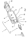
- the EP 1 122 832 A2 relates to a socket for electrically conductive connection to a pin. It comprises a base member having a tubular receiving portion which forms an enclosed receiving space with an insertion opening for the plug pin. It also forms in the receiving space a contact portion for the plug pin.
- the base member further includes a terminal portion for electrically conductive connection to the conductor of a cable.
- the base member may be made of a first material adapted to its function.
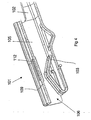
- the spring element has a second region, which is bent by approximately 180 ° to the first region. This is located inside the base element, i. essentially in the receiving space of the base element. It comprises a section which, starting from the insertion opening, extends further into the receiving space and extends toward the contact section of the base element. Following this, a section is again provided on the wall of the tubular receiving section.
- the shape of this separate spring element requires that a connection to the tubular receiving portion is made by welding to achieve a secure support.
- the spring element is intended to consist of a ferrous metal material, for example of a stainless steel or a spring steel.
- the base member is made of an aluminum or an aluminum alloy.
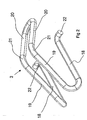
- the spring element is bent in a U-shape from a flat material and forms two opposite contact points, between which the plug pin enters to make an electrical contact.
- the spring element is received in the receiving space of the receiving portion of the base member and contacted this electrically conductive.
- the electrically conductive contact between the male pin and the female connector is made in the region having the less favorable electrical conduction properties. The plug pin only comes into contact with the spring element.
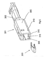
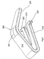
- FIG. 4 shows an embodiment of a socket 101, in which an even more compact design of the base member 102 can be achieved in the region of the receiving portion 105, as in connection with the embodiment according to FIGS. 1 to 3 is possible.
- the contact portion 112 is generated in the socket 101 in the region of the receiving portion 105 of the base member 102 in that the third wall 109 is provided with a projecting into the receiving space 106 imprint. This forms the in the receiving space 106 protruding contact portion 112, which is opposite to the transitions of the spring element 103.
Landscapes
- Coupling Device And Connection With Printed Circuit (AREA)
- Details Of Connecting Devices For Male And Female Coupling (AREA)
- Multi-Conductor Connections (AREA)
- Connector Housings Or Holding Contact Members (AREA)
Claims (9)
- Douille de connexion (1, 101, 301, 401) pour assurer la connexion électrique avec une fiche de connexion (4), notamment une fiche de connexion plate, comprenant- un élément de base (2, 102, 302, 402)- qui présente un tronçon de réception (5, 105, 305, 405) de forme tubulaire formant un logement de réception (6, 106, 306, 406) enfermé et présenant une ouverture d'introduction (11) pour la fiche de connexion (4),- qui forme un tronçon de contact (12) pour la fiche de connexion (4),- et qui présente un tronçon de raccordement (16) servant à la connexion électrique à un conducteur d'un câble,- un élément de ressort (3, 103, 303, 403) séparé,douille dans laquelle- qui présente un tronçon de branche qui, en partant de l'ouverture d'introduction (11), s'engage plus loin à l'intérieur dans le logement de réception (6, 106, 306, 406) et s'étend vers le tronçon de contact (12, 112),- l'élément de base (2, 102, 302, 402) est réalisé en un matériau de haute conductibilité électrique, et- l'élément de ressort (3, 103, 303, 403) séparé est réalisé en un acier à ressort inoxydable, et- est reçu dans sa totalité dans le logement de réception (6, 106, 306, 406),caractérisée- en ce que l'élément de ressort présente deux premiers tronçons de branches (318) qui comportent des tronçons d'enclenchement (322) s'éloignant l'un de l'autre et venant s'engager dans des passages de fixation (313) de l'élément de base (302, 402),- et présente un deuxième tronçon de branche (19, 319) coudé par rapport au premier tronçon de branche (18, 318) respectivement considéré et s'engageant à partir de l'ouverture d'introduction (11) plus profondément dans le logement de réception (6, 106, 306, 406), tout en s'étendant vers le tronçon de contact (12, 112).
- Douille de connexion selon la revendication 7., caractérisée en ce que l'élément de ressort (3, 103, 303, 403) présente à la suite du deuxième tronçon de branche (19, 319), un troisième tronçon de branche (20, 320) qui est coudé par rapport au deuxième tronçon de branche (19, 219, 319) de manière à s'éloigner du tronçon de contact (12, 112), et en qu'une transition (21, 321) de l'élément de ressort (3, 103, 303, 403) entre le deuxième tronçon de branche (19, 319) et le troisième tronçon de branche (20, 320), forme la base d'appui pour la fiche de connexion (4).
- Douille de connexion selon la revendication 1, caractérisée en ce que l'élément de base (2, 102, 302, 402) présente un tronçon de réception (5, 105, 205) de forme tubulaire en section transversale, et le logement de réception (6, 106) est entouré ou enfermé par des parois (7, 8, 9, 10 ; 109) agencées à angle droit les unes par rapport aux autres.
- Douille de connexion selon la revendication 3, caractérisée en ce qu'une paroi (109) est pourvue d'un tronçon faisant saillie dans le logement de réception (106) et constituant le tronçon de contact (112).
- Douille de connexion selon la revendication 3, caractérisée en ce qu'au moins une languette de contact découpée par matriçage dans une paroi (8, 10) et coudée vers l'intérieur du logement de réception (6), forme le tronçon de contact (12).
- Douille de connexion selon la revendication 1, caractérisée en ce que l'élément de ressort (3, 103) est réalisé en un fil rond plié et englobe respectivement deux premiers tronçons de branche (18), deux deuxièmes tronçons de branche (19) et deux troisièmes tronçons de branche (20), les troisièmes tronçons de branche (20) étant reliés l'un à l'autre, et les tronçons d'enclenchement (22) étant coudés hors des premiers tronçons de branche (18) en s'éloignant l'un de l'autre.
- Douille de connexion selon la revendication 1, caractérisée en ce que l'élément de ressort (303, 403) est réalisé par pliage d'un matériau plat.
- Douille de connexion selon la revendication 1, caractérisée en ce que l'élément de base (2, 302) présente une patte d'arrêt (15, 315) qui s'engage entre les deux premiers tronçons de branche (18, 318).
- Douille de connexion selon la revendication 1, caractérisée en ce que l'élément de base (2, 102, 302, 402) est réalisé dans un matériau de tôle par découpage par matriçage et pliage.
Applications Claiming Priority (2)
| Application Number | Priority Date | Filing Date | Title |
|---|---|---|---|
| DE102004018492A DE102004018492B3 (de) | 2004-04-14 | 2004-04-14 | Steckbuchse zum elektrisch leitenden Verbinden mit einem Steckstift, insbesondere Flachsteckstift |
| DE102004018492 | 2004-04-14 |
Publications (2)
| Publication Number | Publication Date |
|---|---|
| EP1587172A1 EP1587172A1 (fr) | 2005-10-19 |
| EP1587172B1 true EP1587172B1 (fr) | 2008-05-14 |
Family
ID=34934293
Family Applications (1)
| Application Number | Title | Priority Date | Filing Date |
|---|---|---|---|
| EP05005668A Not-in-force EP1587172B1 (fr) | 2004-04-14 | 2005-03-16 | Douille pour connection électrique avec une fiche plus particulièrement une fiche plate |
Country Status (6)
| Country | Link |
|---|---|
| US (1) | US7118428B2 (fr) |
| EP (1) | EP1587172B1 (fr) |
| JP (1) | JP4205692B2 (fr) |
| AT (1) | ATE395729T1 (fr) |
| DE (2) | DE102004018492B3 (fr) |
| ES (1) | ES2305929T3 (fr) |
Families Citing this family (5)
| Publication number | Priority date | Publication date | Assignee | Title |
|---|---|---|---|---|
| ES2370849T3 (es) | 2007-04-26 | 2011-12-23 | Multi-Holding Ag | Dispositivo de contacto para proporcionar un contacto eléctrico entre elementos conductores de corriente planos. |
| JP2009283308A (ja) * | 2008-05-22 | 2009-12-03 | Yazaki Corp | 雌型端子 |
| JP5568274B2 (ja) * | 2009-10-13 | 2014-08-06 | 日本航空電子工業株式会社 | 雌コンタクト |
| DE102012002145A1 (de) * | 2012-02-04 | 2013-08-08 | Kostal Kontakt Systeme Gmbh | Hülsenkontakt für einen elektrischen Nullkraftsteckverbinder |
| JP6564810B2 (ja) * | 2017-05-18 | 2019-08-21 | 矢崎総業株式会社 | 接続端子 |
Family Cites Families (12)
| Publication number | Priority date | Publication date | Assignee | Title |
|---|---|---|---|---|
| US2471923A (en) * | 1948-05-29 | 1949-05-31 | Ark Les Switch Corp | Electric connector with spring wire |
| US3120989A (en) * | 1961-04-10 | 1964-02-11 | Burndy Corp | Electrical socket contact |
| JPH02199780A (ja) * | 1989-01-30 | 1990-08-08 | Yazaki Corp | 低挿入力端子 |
| US5271741A (en) * | 1990-02-21 | 1993-12-21 | Yazaki Corporation | Female socket contact |
| JPH0633659Y2 (ja) * | 1990-02-21 | 1994-08-31 | 矢崎総業株式会社 | 雌型端子金具 |
| JPH0494275U (fr) * | 1991-01-11 | 1992-08-17 | ||
| US5980336A (en) * | 1995-06-09 | 1999-11-09 | Lear Automotive Dearborn, Inc. | Electrical terminal |
| US5810627A (en) * | 1996-01-11 | 1998-09-22 | Molex Incorporated | Female electrical terminal |
| US6062918A (en) * | 1996-07-01 | 2000-05-16 | The Whitaker Corporation | Electrical receptacle contact assembly |
| EP1122832A3 (fr) * | 2000-01-31 | 2001-09-26 | Tyco Electronics AMP GmbH | Douille de contact |
| US6293833B1 (en) * | 2001-01-05 | 2001-09-25 | Yazaki North America | Low insertion force, high contact force terminal spring |
| JP2003338334A (ja) * | 2002-05-20 | 2003-11-28 | Yazaki Corp | 雌端子およびその接続構造ならびにワイヤハーネス |
-
2004
- 2004-04-14 DE DE102004018492A patent/DE102004018492B3/de not_active Expired - Fee Related
-
2005
- 2005-03-16 AT AT05005668T patent/ATE395729T1/de not_active IP Right Cessation
- 2005-03-16 EP EP05005668A patent/EP1587172B1/fr not_active Not-in-force
- 2005-03-16 ES ES05005668T patent/ES2305929T3/es active Active
- 2005-03-16 DE DE502005004074T patent/DE502005004074D1/de not_active Expired - Fee Related
- 2005-04-12 JP JP2005114737A patent/JP4205692B2/ja not_active Expired - Fee Related
- 2005-04-13 US US11/104,500 patent/US7118428B2/en not_active Expired - Fee Related
Also Published As
| Publication number | Publication date |
|---|---|
| DE102004018492B3 (de) | 2006-02-09 |
| JP2005302730A (ja) | 2005-10-27 |
| JP4205692B2 (ja) | 2009-01-07 |
| ES2305929T3 (es) | 2008-11-01 |
| US20050233651A1 (en) | 2005-10-20 |
| US7118428B2 (en) | 2006-10-10 |
| DE502005004074D1 (de) | 2008-06-26 |
| EP1587172A1 (fr) | 2005-10-19 |
| ATE395729T1 (de) | 2008-05-15 |
Similar Documents
| Publication | Publication Date | Title |
|---|---|---|
| EP1780835B1 (fr) | Contact électrique | |
| DE19944280C1 (de) | Elektrischer Buchsenkontakt mit Führungssteg | |
| DE102017119287B4 (de) | Modularer Steckverbinder für Leiterplatten | |
| DE19835020A1 (de) | Buchsenkontakt | |
| DE102016221351A1 (de) | Flachkontaktbuchse mit Ausleger | |
| EP2131449A1 (fr) | Borne unique | |
| EP3018761B1 (fr) | Borne de connexion de carte de circuit imprime | |
| EP1429423B1 (fr) | Connecteur électrique à fiche ayant un boîtier et un contact à courant fort | |
| DE10119695B4 (de) | Steckverbinder für elektronische Bauelemente | |
| EP2915218B1 (fr) | Connecteur à fiche à partie isolante | |
| DE112016002791T5 (de) | Gemeinschaftsverbinder | |
| EP1587172B1 (fr) | Douille pour connection électrique avec une fiche plus particulièrement une fiche plate | |
| DE4016114C2 (de) | Elektrischer Mehrkontakt-Verbinder, der eine geringe Verbindungs- und Trennkraft erfordert | |
| DE69624309T2 (de) | Elektrisches Anschlussteil mit Verriegelungszunge | |
| EP1215763B2 (fr) | Contact femelle pour un connecteur électrique | |
| DE4322790C2 (de) | Schraubklemme mit u-förmigem Klemmkörper | |
| DE112022005910T5 (de) | Anschlusseinheit, Buchsenanschluss und Steckeranschluss | |
| EP2551963B1 (fr) | Elément de raccordement électrique | |
| EP1720222B1 (fr) | Connecteur électrique, notamment pour des systèmes d' allumage d' airbag | |
| DE19840648C1 (de) | Elektrischer Steckverbinder | |
| EP4169127A1 (fr) | Contact électrique | |
| DE102005054590A1 (de) | Elektrischer Steckverbinder | |
| DE102006022206B3 (de) | Elektrischer Steckanschluß | |
| DE10227235A1 (de) | Leiteranschluss | |
| DE10331034B4 (de) | Kontaktbuchse |
Legal Events
| Date | Code | Title | Description |
|---|---|---|---|
| PUAI | Public reference made under article 153(3) epc to a published international application that has entered the european phase |
Free format text: ORIGINAL CODE: 0009012 |
|
| AK | Designated contracting states |
Kind code of ref document: A1 Designated state(s): AT BE BG CH CY CZ DE DK EE ES FI FR GB GR HU IE IS IT LI LT LU MC NL PL PT RO SE SI SK TR |
|
| AX | Request for extension of the european patent |
Extension state: AL BA HR LV MK YU |
|
| 17P | Request for examination filed |
Effective date: 20060215 |
|
| AKX | Designation fees paid |
Designated state(s): AT BE BG CH CY CZ DE DK EE ES FI FR GB GR HU IE IS IT LI LT LU MC NL PL PT RO SE SI SK TR |
|
| GRAP | Despatch of communication of intention to grant a patent |
Free format text: ORIGINAL CODE: EPIDOSNIGR1 |
|
| RTI1 | Title (correction) |
Free format text: FEMALE TERMINAL FOR THE ELECTRICALLY CONDUCTIVE CONNECTION TO A TERMINAL PIN, IN PARTICULAR A FLAT TERMINAL PIN |
|
| GRAS | Grant fee paid |
Free format text: ORIGINAL CODE: EPIDOSNIGR3 |
|
| GRAA | (expected) grant |
Free format text: ORIGINAL CODE: 0009210 |
|
| AK | Designated contracting states |
Kind code of ref document: B1 Designated state(s): AT BE BG CH CY CZ DE DK EE ES FI FR GB GR HU IE IS IT LI LT LU MC NL PL PT RO SE SI SK TR |
|
| REG | Reference to a national code |
Ref country code: GB Ref legal event code: FG4D Free format text: NOT ENGLISH |
|
| REG | Reference to a national code |
Ref country code: CH Ref legal event code: EP |
|
| REG | Reference to a national code |
Ref country code: IE Ref legal event code: FG4D Free format text: LANGUAGE OF EP DOCUMENT: GERMAN |
|
| REF | Corresponds to: |
Ref document number: 502005004074 Country of ref document: DE Date of ref document: 20080626 Kind code of ref document: P |
|
| REG | Reference to a national code |
Ref country code: RO Ref legal event code: EPE |
|
| REG | Reference to a national code |
Ref country code: SE Ref legal event code: TRGR |
|
| PG25 | Lapsed in a contracting state [announced via postgrant information from national office to epo] |
Ref country code: SI Free format text: LAPSE BECAUSE OF FAILURE TO SUBMIT A TRANSLATION OF THE DESCRIPTION OR TO PAY THE FEE WITHIN THE PRESCRIBED TIME-LIMIT Effective date: 20080514 |
|
| PG25 | Lapsed in a contracting state [announced via postgrant information from national office to epo] |
Ref country code: FI Free format text: LAPSE BECAUSE OF FAILURE TO SUBMIT A TRANSLATION OF THE DESCRIPTION OR TO PAY THE FEE WITHIN THE PRESCRIBED TIME-LIMIT Effective date: 20080514 |
|
| REG | Reference to a national code |
Ref country code: ES Ref legal event code: FG2A Ref document number: 2305929 Country of ref document: ES Kind code of ref document: T3 |
|
| NLV1 | Nl: lapsed or annulled due to failure to fulfill the requirements of art. 29p and 29m of the patents act | ||
| PG25 | Lapsed in a contracting state [announced via postgrant information from national office to epo] |
Ref country code: PL Free format text: LAPSE BECAUSE OF FAILURE TO SUBMIT A TRANSLATION OF THE DESCRIPTION OR TO PAY THE FEE WITHIN THE PRESCRIBED TIME-LIMIT Effective date: 20080514 Ref country code: NL Free format text: LAPSE BECAUSE OF FAILURE TO SUBMIT A TRANSLATION OF THE DESCRIPTION OR TO PAY THE FEE WITHIN THE PRESCRIBED TIME-LIMIT Effective date: 20080514 |
|
| PG25 | Lapsed in a contracting state [announced via postgrant information from national office to epo] |
Ref country code: IS Free format text: LAPSE BECAUSE OF FAILURE TO SUBMIT A TRANSLATION OF THE DESCRIPTION OR TO PAY THE FEE WITHIN THE PRESCRIBED TIME-LIMIT Effective date: 20080914 |
|
| REG | Reference to a national code |
Ref country code: IE Ref legal event code: FD4D |
|
| PG25 | Lapsed in a contracting state [announced via postgrant information from national office to epo] |
Ref country code: LT Free format text: LAPSE BECAUSE OF FAILURE TO SUBMIT A TRANSLATION OF THE DESCRIPTION OR TO PAY THE FEE WITHIN THE PRESCRIBED TIME-LIMIT Effective date: 20080514 Ref country code: IE Free format text: LAPSE BECAUSE OF FAILURE TO SUBMIT A TRANSLATION OF THE DESCRIPTION OR TO PAY THE FEE WITHIN THE PRESCRIBED TIME-LIMIT Effective date: 20080514 Ref country code: DK Free format text: LAPSE BECAUSE OF FAILURE TO SUBMIT A TRANSLATION OF THE DESCRIPTION OR TO PAY THE FEE WITHIN THE PRESCRIBED TIME-LIMIT Effective date: 20080514 Ref country code: PT Free format text: LAPSE BECAUSE OF FAILURE TO SUBMIT A TRANSLATION OF THE DESCRIPTION OR TO PAY THE FEE WITHIN THE PRESCRIBED TIME-LIMIT Effective date: 20081014 Ref country code: CZ Free format text: LAPSE BECAUSE OF FAILURE TO SUBMIT A TRANSLATION OF THE DESCRIPTION OR TO PAY THE FEE WITHIN THE PRESCRIBED TIME-LIMIT Effective date: 20080514 |
|
| PLBE | No opposition filed within time limit |
Free format text: ORIGINAL CODE: 0009261 |
|
| STAA | Information on the status of an ep patent application or granted ep patent |
Free format text: STATUS: NO OPPOSITION FILED WITHIN TIME LIMIT |
|
| 26N | No opposition filed |
Effective date: 20090217 |
|
| PG25 | Lapsed in a contracting state [announced via postgrant information from national office to epo] |
Ref country code: EE Free format text: LAPSE BECAUSE OF FAILURE TO SUBMIT A TRANSLATION OF THE DESCRIPTION OR TO PAY THE FEE WITHIN THE PRESCRIBED TIME-LIMIT Effective date: 20080514 Ref country code: BG Free format text: LAPSE BECAUSE OF FAILURE TO SUBMIT A TRANSLATION OF THE DESCRIPTION OR TO PAY THE FEE WITHIN THE PRESCRIBED TIME-LIMIT Effective date: 20080814 |
|
| BERE | Be: lapsed |
Owner name: YAZAKI EUROPE LTD. Effective date: 20090331 |
|
| PG25 | Lapsed in a contracting state [announced via postgrant information from national office to epo] |
Ref country code: MC Free format text: LAPSE BECAUSE OF NON-PAYMENT OF DUE FEES Effective date: 20090331 |
|
| REG | Reference to a national code |
Ref country code: CH Ref legal event code: PL |
|
| EUG | Se: european patent has lapsed | ||
| GBPC | Gb: european patent ceased through non-payment of renewal fee |
Effective date: 20090316 |
|
| REG | Reference to a national code |
Ref country code: FR Ref legal event code: ST Effective date: 20091130 |
|
| PG25 | Lapsed in a contracting state [announced via postgrant information from national office to epo] |
Ref country code: DE Free format text: LAPSE BECAUSE OF NON-PAYMENT OF DUE FEES Effective date: 20091001 Ref country code: CH Free format text: LAPSE BECAUSE OF NON-PAYMENT OF DUE FEES Effective date: 20090331 Ref country code: LI Free format text: LAPSE BECAUSE OF NON-PAYMENT OF DUE FEES Effective date: 20090331 |
|
| PG25 | Lapsed in a contracting state [announced via postgrant information from national office to epo] |
Ref country code: BE Free format text: LAPSE BECAUSE OF NON-PAYMENT OF DUE FEES Effective date: 20090331 Ref country code: SK Free format text: LAPSE BECAUSE OF NON-PAYMENT OF DUE FEES Effective date: 20090316 |
|
| PG25 | Lapsed in a contracting state [announced via postgrant information from national office to epo] |
Ref country code: RO Free format text: LAPSE BECAUSE OF NON-PAYMENT OF DUE FEES Effective date: 20080514 Ref country code: GB Free format text: LAPSE BECAUSE OF NON-PAYMENT OF DUE FEES Effective date: 20090316 Ref country code: FR Free format text: LAPSE BECAUSE OF NON-PAYMENT OF DUE FEES Effective date: 20091123 |
|
| REG | Reference to a national code |
Ref country code: ES Ref legal event code: FD2A Effective date: 20090317 |
|
| PG25 | Lapsed in a contracting state [announced via postgrant information from national office to epo] |
Ref country code: AT Free format text: LAPSE BECAUSE OF NON-PAYMENT OF DUE FEES Effective date: 20090316 |
|
| PG25 | Lapsed in a contracting state [announced via postgrant information from national office to epo] |
Ref country code: ES Free format text: LAPSE BECAUSE OF NON-PAYMENT OF DUE FEES Effective date: 20090317 |
|
| PG25 | Lapsed in a contracting state [announced via postgrant information from national office to epo] |
Ref country code: GR Free format text: LAPSE BECAUSE OF FAILURE TO SUBMIT A TRANSLATION OF THE DESCRIPTION OR TO PAY THE FEE WITHIN THE PRESCRIBED TIME-LIMIT Effective date: 20080815 |
|
| PG25 | Lapsed in a contracting state [announced via postgrant information from national office to epo] |
Ref country code: IT Free format text: LAPSE BECAUSE OF NON-PAYMENT OF DUE FEES Effective date: 20090316 |
|
| PG25 | Lapsed in a contracting state [announced via postgrant information from national office to epo] |
Ref country code: LU Free format text: LAPSE BECAUSE OF NON-PAYMENT OF DUE FEES Effective date: 20090316 |
|
| PG25 | Lapsed in a contracting state [announced via postgrant information from national office to epo] |
Ref country code: SE Free format text: LAPSE BECAUSE OF NON-PAYMENT OF DUE FEES Effective date: 20090317 |
|
| PG25 | Lapsed in a contracting state [announced via postgrant information from national office to epo] |
Ref country code: HU Free format text: LAPSE BECAUSE OF FAILURE TO SUBMIT A TRANSLATION OF THE DESCRIPTION OR TO PAY THE FEE WITHIN THE PRESCRIBED TIME-LIMIT Effective date: 20081115 |
|
| PG25 | Lapsed in a contracting state [announced via postgrant information from national office to epo] |
Ref country code: TR Free format text: LAPSE BECAUSE OF FAILURE TO SUBMIT A TRANSLATION OF THE DESCRIPTION OR TO PAY THE FEE WITHIN THE PRESCRIBED TIME-LIMIT Effective date: 20080514 |
|
| PG25 | Lapsed in a contracting state [announced via postgrant information from national office to epo] |
Ref country code: CY Free format text: LAPSE BECAUSE OF FAILURE TO SUBMIT A TRANSLATION OF THE DESCRIPTION OR TO PAY THE FEE WITHIN THE PRESCRIBED TIME-LIMIT Effective date: 20080514 |