EP1586702A1 - Twin-wire former for a machine for manufacturing a fibrous web - Google Patents
Twin-wire former for a machine for manufacturing a fibrous web Download PDFInfo
- Publication number
- EP1586702A1 EP1586702A1 EP05102625A EP05102625A EP1586702A1 EP 1586702 A1 EP1586702 A1 EP 1586702A1 EP 05102625 A EP05102625 A EP 05102625A EP 05102625 A EP05102625 A EP 05102625A EP 1586702 A1 EP1586702 A1 EP 1586702A1
- Authority
- EP
- European Patent Office
- Prior art keywords
- twin
- wire
- wire former
- strips
- former
- Prior art date
- Legal status (The legal status is an assumption and is not a legal conclusion. Google has not performed a legal analysis and makes no representation as to the accuracy of the status listed.)
- Granted
Links
Images

Classifications
-
- D—TEXTILES; PAPER
- D21—PAPER-MAKING; PRODUCTION OF CELLULOSE
- D21F—PAPER-MAKING MACHINES; METHODS OF PRODUCING PAPER THEREON
- D21F9/00—Complete machines for making continuous webs of paper
- D21F9/003—Complete machines for making continuous webs of paper of the twin-wire type
Definitions
- the invention relates to a twin-wire former of a machine for producing a Fiber web, in particular a paper or board web, with two circumferential endless screens, both over a peripheral area of a respective deflecting element, especially a breast roll, run, then at least until to achieve an impingement device to form a wedge-shaped Stoffeinlaufspalts, directly the at least one of a headbox than Pulp suspension jet applied pulp suspension in training each Strahlauf Economicspp receives on the two sieves, converge and which then form a twin-wire section, in which the two sieves and the at least one intermediate pulp suspension over several Forming and drainage elements are guided.
- twin-wire former has been known in the art for some time and it is commonly referred to as a so-called last-gap former "(Blade-Gapformer).
- the drainage of the introduced begins Fibrous suspension on a box equipped with ceramic strips, above which curved surface the two sieves converge and the first drainage takes place.
- the box can, depending on the embodiment, to the environment open or closed executed. In a closed box is the application of vacuum possible. It can also be about individual ceramic strips act, which are preferably mounted on support ribs.
- a disadvantage of this design is that the applied vacuum is not adjustable is and thus not independent of the sieve speed is adjustable. Of Further, even under normal operating conditions, the grooves may be more or less less quickly and heavily pollute.
- the weir and the open water sump also have the disadvantage that they are the Obstruct air removal from the sieve. Furthermore sits in free flow of the box in Usually so high up that the entrained air already from the manufactured Fiber web (fiber mat) is included.
- the impingement device is designed as an impingement shoe, which has a covering with several in succession direction arranged strips with intervening has free drainage holes, each with a fixed and open surface touching the rotating sieve, and the one comprehensive Box has, the box bottom so close to the upstream in the direction Sieblaufraum Breast roller is arranged that the box bottom at least partially is guided around the breast roll.
- This solution enables the operation of the twin-wire former even at high levels Screening speeds ⁇ 1,500 m / min, preferably ⁇ 1,700 m / min, and at low Basis weights, without water streaks and / or bright spots in the produced fibrous web occur.
- twin-wire former according to the invention can also be used in conversions of existing systems find their use, such as in conversions BelBaie shapers.
- the box bottom preferably has a highest - seen in the vertical direction Point up to a vertical height in the range of 10 to 700 mm, preferably from 100 to 40 mm, above the beginning of the first in the direction of the direction of sieve free drainage hole is located.
- the white water can in the box freely over the breast roll crest expire.
- the strips preferably on run-side scraping edges, wherein in Sieblaufraum second and subsequent bar a respective Guiding surface, whose geometrically linear extension of the box bottom not touched on the inside. This will ensure that of the scraping edges discharged white water freely over the highest point of the box bottom is thrown and again the emergence of an open sump completely is avoided.
- the strips have a width ⁇ 150 mm, preferably ⁇ 100 mm, in particular ⁇ 60 mm, on.
- the open surface of the impingement shoe can also be interrupted, Machine-wide and transverse to Sieblaufraum aligned slots in the wire direction aligned herringbone slots, drilling and / or other having shaped openings, these embodiments merely by way of example Character. Other design options are obvious possible.
- the Impingement shoe preferably at least one, preferably two or more curved regions with preferably different lengths, their radii in Sieblaufraum each have a greater value.
- the radius of the first range preferably has a value in the range of 0.6 to 4 m, preferably from 1 to 2 m, and the radius of the second region preferably has a value in the range of 2 to 5 m, preferably 3 m, whereas the length of the The first range preferably has a value in the range of 15 to 150 mm, preferably from 70 to 120 mm, and the length of the second region preferably one Value in the range of 90 to 250 mm. These dimensions are special advantageous at high speeds.
- the forming fibrous web continuously in the course of their drainage is drained more gently, the free drainage holes have different On sizes that decrease in amount preferably in Sieblaufraum.
- the air contained in the pulp suspension is effectively removed, is the impingement shoe by means of at least one vacuum source with a vacuum ⁇ 0.5 kPa, preferably ⁇ 2 kPa, in particular ⁇ 5 kPa, controllable / controllable suctioned.
- the removal of the air-white water mixture is effectively supported.
- Impingementschuh side of the twin-wire section are advantageously arranged several strips that are flexible to the fitting Sieve are pressed and the at least partially opposite the free drainage holes can be arranged. This favors one increased removal of accumulating white water in the impingement shoe.
- the twin-wire former according to the invention is suitable for all possible embodiments, so that the twin-wire section at an angle of 0 ° to 90 ° can be arranged to the horizontal.
- the twin-wire former can therefore be used as a horizontal, be designed as a vertical or inclined form.
- FIG. 1 shows a schematic partial side view of a twin-wire former 1 according to the known prior art.
- the drainage of the introduced pulp suspension 13 begins on a box 17 equipped with ceramic strips 17.1 to 17.4 box 18, on the curved surface 19, the two wires 3, 4 converge and the first dewatering takes place.
- the box 18 has at the outset a Auflautang 20 for the protection of the beam after the Strahlauf Economicsticiantician 11 3 , 14 4 .
- the box 18 may, depending on the embodiment, open to the environment or closed, as shown in Figure 1, executed. In a closed box 18, the use of vacuum is possible. It may also be in unillustrated embodiment also to individual ceramic strips, which are preferably mounted on support ribs.
- FIG. 2 shows a further schematic partial side view of a twin-wire former 1 according to the known prior art.
- the impingement device 9 in this case comprises several in the direction S of the machine direction (arrow) arranged after the breast roll 7.1 wide ceramic strips 23 with so-called Foilrillen 24, as for example from the already mentioned German Offenlegungsschrift DE 100 84 722 T1 are known.
- the means of the ceramic strips 23rd from the pulp suspension 13 discharged white water is by means of a guide 25, in particular a baffle 25.1, discharged via the breast roller 7.1.
- In Sieblaufraum S (arrow) after the wide ceramic strips 23 is a with arranged a vacuum applied box 26, which in turn several ceramic strips 27.1 to 27.3 in the manner already described.
- FIG. 3 now shows a schematic partial side view of an embodiment of the twin-wire former 1 according to the invention.
- twin-wire former 1 With regard to the basic structure of this twin wire former 1 will turn refer to the description of the twin-wire former 1 of Figure 1.
- the impingement device 9 is designed as an impingement shoe 9.1 which has a covering 28 with a plurality of strips 29.1 to 29.6 disposed successively and preferably parallel to one another in the direction of wire flow S (arrow) with free drainage openings 30.1 to 30.5 interposed therebetween, each having a stationary and open surface 31.1 to 31.6 touch the rotating sieve 3, and has a comprehensive box 32, the box bottom 33 is arranged so close to the direction in the wire direction S (arrow) upstream breast roller 7.1, that the box bottom 33 is at least partially guided around the breast roller 7.1.
- the number of strips shown in Figure 1 has only exemplary character; Of course, more or fewer strips can find their use.
- the first strip 29.1 in the direction of the direction of movement S (arrow) is also shown as a known casserole for supporting the screen 3 after the beam impingement point 14 3 .
- the box bottom 33 has a - seen in the vertical direction - highest point B, by a vertical height H v in the range of 10 to 700 mm, preferably 100 to 400 mm, above the beginning of the S in the direction of wire direction S (arrow) first free Drainage opening 30.1 is located.
- the strips 29.1 to 29.6 have run-off side scraping edges 34.1 to 34.6, wherein in the direction of wire direction S (arrow) second strip 29.2 and their subsequent strip 29.3 to 29.6 a respective guide surface 35.2 to 35.6, the geometrically linear extension V 29.2 to V 29.6 the box bottom 33 not touched on the inside.
- the respective guide surface 35.2 to 35.6 is preferably arranged at an angle ⁇ ⁇ 80 °, preferably ⁇ 60 °, to the respective wire direction S (arrow) and the strips 29.1 to 29.6 have a width B 29.1 to B 29.6 (only giving the width B 29.4 ) ⁇ 150 mm, preferably ⁇ 100 mm, in particular ⁇ 60 mm.
- the open surface 31 of the impingement shoe 9.1 also interrupted, machine width and transverse to Sieblaufraum S (arrow) aligned slots, aligned in the wire direction S (arrow) Herringbone slots, holes and / or differently shaped openings, in particular breakthroughs.
- the impingement shoe 9.1 has two curved regions B 1 , B 2 , preferably with different lengths L 1 , L 2 , whose radii R 1 , R 2 each have a greater value in the direction of wire run S (arrow).
- the radius R 1 of the first region B 1 has a value in the range of 0.6 to 4 m, preferably 1 to 2 m
- the radius R 2 of the second region B 2 has a value in the range of 2 to 5 m, 3 m
- the length L 1 of the first region B 1 has a value in the range of 15 to 150 mm, preferably 70 to 120 mm
- the length L 2 of the second region B 2 has a value in the region of 90 up to 250 mm.
- several areas with these properties may be present.
- the free drainage holes 30.1 to 30.5 also have different Sizes, which decrease in terms of amount preferably in Sieblaufraum S (arrow).
- the impingement shoe 9.1 by means of at least one not shown,
- the vacuum source known to the person skilled in the art with a vacuum V ⁇ 0.5 kPa, preferably ⁇ 2 kPa, in particular ⁇ 5 kPa, regularly / controllably evacuated and on the Impingementschuh 9.1 opposite side of the Doppelsiebumble 15, a plurality of strips 36 are arranged, which are flexible in a known manner can be pressed against the adjacent sieve 4.
- the flexible contact strips 36 are at least partially opposite the free drainage holes 30.1 to 30.5 arranged.
- the two screens 3, 4 have a respective screen speed v ⁇ 1,500 m / min, preferably ⁇ 1,700 m / min, and the twin-wire section 15 is under one Angle ⁇ of 0 ° to 90 ° to the horizontal H arranged.
- the inventive Twin-wire former 1 can thus be used as a horizontal, vertical or skew former be educated.
- a sheet forming system a machine for producing a stain-free fibrous web with a very good formation even at high speeds is created.
Landscapes
- Paper (AREA)
- Preliminary Treatment Of Fibers (AREA)
- Nonwoven Fabrics (AREA)
Abstract
Description
Die Erfindung betrifft einen Doppelsiebformer einer Maschine zur Herstellung einer Faserstoffbahn, insbesondere einer Papier- oder Kartonbahn, mit zwei umlaufenden endlosen Sieben, die beide über einen Umfangsbereich eines jeweiligen Umlenkelements, insbesondere einer Brustwalze, laufen, die danach zumindest bis zum Erreichen einer Impingementeinrichtung unter Bildung eines keilförmigen Stoffeinlaufspalts, der unmittelbar die mindestens eine von einem Stoffauflauf als Faserstoffsuspensionsstrahl ausgebrachte Faserstoffsuspension bei Ausbildung jeweiliger Strahlauftreffpunkte auf den beiden Sieben aufnimmt, zusammenlaufen und die anschließend eine Doppelsiebstrecke bilden, in welcher die beiden Siebe und die mindestens eine dazwischen liegende Faserstoffsuspension über mehrere Formier- und Entwässerungselemente geführt sind.The invention relates to a twin-wire former of a machine for producing a Fiber web, in particular a paper or board web, with two circumferential endless screens, both over a peripheral area of a respective deflecting element, especially a breast roll, run, then at least until to achieve an impingement device to form a wedge-shaped Stoffeinlaufspalts, directly the at least one of a headbox than Pulp suspension jet applied pulp suspension in training each Strahlauftreffpunkte receives on the two sieves, converge and which then form a twin-wire section, in which the two sieves and the at least one intermediate pulp suspension over several Forming and drainage elements are guided.
Ein derartiger Doppelsiebformer ist in Fachkreisen seit geraumer Zeit bekannt und er wird gemeinhin als so genannter Leisten-Spaltformer "(Blade-Gapformer" bezeichnet.Such a twin-wire former has been known in the art for some time and it is commonly referred to as a so-called last-gap former "(Blade-Gapformer".
An bekannten Leisten-Spaltformern beginnt die Entwässerung der eingebrachten Faserstoffsuspension auf einem mit Keramikleisten bestückten Kasten, über dessen gekrümmter Oberfläche die beiden Siebe zusammenlaufen und die erste Entwässerung stattfindet. Der Kasten kann, je nach Ausführungsform, zur Umgebung hin offen oder geschlossen ausgeführt sein. Bei einem geschlossenen Kasten ist die Anwendung von Vakuum möglich. Es kann sich auch um einzelne Keramikleisten handeln, die vorzugsweise auf Tragrippen befestigt sind. At known inguinal gap formers, the drainage of the introduced begins Fibrous suspension on a box equipped with ceramic strips, above which curved surface the two sieves converge and the first drainage takes place. The box can, depending on the embodiment, to the environment open or closed executed. In a closed box is the application of vacuum possible. It can also be about individual ceramic strips act, which are preferably mounted on support ribs.
Bei hohen Geschwindigkeiten treten an diesem Formertyp oft helle Flecken in der hergestellten Faserstoffbahn auf, da die beim Strahleinschuss der Faserstoffsuspension in den Stoffeinlaufspalt eingeschleppte Luft, sowohl im Faserstoffsuspensionsstrahl als auch in den Sieben, nicht ausreichend durch die beiden Siebe entfernt werden kann.At high speeds often occur in this form of graders bright spots in the produced fibrous web, since the at the jet injection of the pulp suspension air entrained in the stock intake slit, both in the pulp suspension jet as well as in the sieves, not sufficiently removed by the two sieves can be.
Damit die eingeschleppte Luft verbessert entfernt wird, hat man in der Vergangenheit an offenen und einzelne Keramikleisten aufweisenden Kästen so genannte Foilrillen in einzelne Keramikleisten eingearbeitet, die durch das dabei im Betrieb entstehende Foilvakuum die eingeschleppte Luft absaugen sollen. Eine derartige Ausführung ist beispielsweise aus der deutschen Offenlegungsschrift DE 100 84 722 T1 bekannt. Die Ausführung weist eine Vielzahl an Rillen auf, die im Mittelteil ausgebildet sind, wobei die Rillen entlang der vorderen Breite zu einer Entleerungsöffnung im hinteren Teil laufen.In order to remove the introduced air better, one has in the past so-called boxes on open and individual ceramic strips Foil grooves incorporated into individual ceramic strips, by the case during operation resulting Foulvakuum suck the entrained air. Such Execution is for example from German patent application DE 100 84 722 T1 known. The design has a plurality of grooves in the middle part are formed, wherein the grooves along the front width to a discharge opening run in the back.
Nachteilig an dieser Ausführung ist, dass das angelegte Vakuum nicht einstellbar ist und somit nicht unabhängig von der Siebgeschwindigkeit einstellbar ist. Des Weiteren können die Rillen selbst unter normalen Betriebsbedingungen mehr oder weniger schnell und stark verschmutzen. An geschlossenen Kästen hat man bereits ein Vakuum angelegt, jedoch muss dabei entweder hinter den Keramikleisten ein Stauwehr oder ein offener Wassersumpf installiert sein. Ansonsten beginnt die Vakuumzone derart spät, dass das aus der Faserstoffsuspension entnommene Siebwasser im Kasten frei über dem Brustwalzenscheitel ablaufen kann. Das Stauwehr und der offene Wassersumpf haben zudem den Nachteil, dass sie die Luftabfuhr vom Sieb behindern. Weiterhin sitzt bei freiem Ablauf der Kasten im Regelfall so weit oben, dass die eingeschleppte Luft schon von der herzustellenden Faserstoffbahn (Fasermatte) eingeschlossen ist.A disadvantage of this design is that the applied vacuum is not adjustable is and thus not independent of the sieve speed is adjustable. Of Further, even under normal operating conditions, the grooves may be more or less less quickly and heavily pollute. At closed boxes one already has a vacuum is applied, but must be either behind the ceramic strips be installed a weir or an open water sump. Otherwise, the Vacuum zone so late that the removed from the pulp suspension White water in the box can drain freely over the breast roll crest. The The weir and the open water sump also have the disadvantage that they are the Obstruct air removal from the sieve. Furthermore sits in free flow of the box in Usually so high up that the entrained air already from the manufactured Fiber web (fiber mat) is included.
Es ist also Aufgabe der Erfindung, einen Doppelsiebformer einer Maschine zur Herstellung einer fleckenfreien Faserstoffbahn infolge einer störungsfreien Abfuhr sowohl von eingeschleppter Luft als auch von aus der Faserstoffsuspension entnommenem Siebwasser im initialen Entwässerungsbereich anzugeben. It is therefore an object of the invention to provide a twin-wire former of a machine for Production of a stain-free fibrous web as a result of trouble-free removal both of entrained air and taken from the pulp suspension Specify white water in the initial drainage area.
Diese Aufgabe wird erfindungsgemäß, dadurch gelöst, dass die Impingementeinrichtung als ein Impingementschuh ausgebildet ist, der einen Belag mit mehreren in Sieblaufrichtung nacheinander angeordneten Leisten mit dazwischen liegenden freien Entwässerungsöffnungen aufweist, die mit einer jeweils ortsfesten und offenen Oberfläche das umlaufende Sieb berühren, und der einen umfassenden Kasten aufweist, dessen Kastenboden derart dicht an der in Sieblaufrichtung vorgeordneten Brustwalze angeordnet ist, dass der Kastenboden zumindest bereichsweise um die Brustwalze herumgeführt ist.This object is achieved according to the invention in that the impingement device is designed as an impingement shoe, which has a covering with several in succession direction arranged strips with intervening has free drainage holes, each with a fixed and open surface touching the rotating sieve, and the one comprehensive Box has, the box bottom so close to the upstream in the direction Sieblaufrichtung Breast roller is arranged that the box bottom at least partially is guided around the breast roll.
Diese Lösung ermöglicht den Betrieb des Doppelsiebformers selbst bei hohen Siebgeschwindigkeiten ≥ 1.500 m/min, vorzugsweise ≥ 1.700 m/min, und bei niedrigen Flächengewichten, ohne dass Wasserstreifen und/oder helle Flecken in der hergestellten Faserstoffbahn auftreten.This solution enables the operation of the twin-wire former even at high levels Screening speeds ≥ 1,500 m / min, preferably ≥ 1,700 m / min, and at low Basis weights, without water streaks and / or bright spots in the produced fibrous web occur.
Weiterhin ergeben sich eine sehr gute Formation und sehr gute Querprofile, insbesondere Flächengewichts- und Aschequerprofil, in der hergestellten Faserstoffbahn.Furthermore, there is a very good formation and very good cross-sections, in particular Basis weight and ash cross profile, in the produced fibrous web.
Ferner kann der erfindungsgemäße Doppelsiebformer auch bei Umbauten von vorhandenen Systemen seinen Einsatz finden, wie beispielsweise bei Umbauten von BelBaie-Formern.Furthermore, the twin-wire former according to the invention can also be used in conversions of existing systems find their use, such as in conversions BelBaie shapers.
Der Kastenboden weist bevorzugt einen - in vertikaler Richtung gesehen - höchsten Punkt auf, der um eine vertikale Höhe im Bereich von 10 bis 700 mm, vorzugsweise von 100 bis 40 mm, über dem Beginn der in Sieblaufrichtung ersten freien Entwässerungsöffnung liegt. Dies beeinflusst die störungsfreie Abfuhr von aus der Faserstoffsuspension entnommenem Siebwasser im initialen Entwässerungsbereich in besonders günstigem Maße, ohne dass dabei ein offener Wassersumpf entsteht. Das Siebwasser kann im Kasten frei über dem Brustwalzenscheitel ablaufen. The box bottom preferably has a highest - seen in the vertical direction Point up to a vertical height in the range of 10 to 700 mm, preferably from 100 to 40 mm, above the beginning of the first in the direction of the direction of sieve free drainage hole is located. This influences the trouble-free removal of white water taken from the pulp suspension in the initial drainage area in a particularly favorable extent, without causing an open sump arises. The white water can in the box freely over the breast roll crest expire.
Weiterhin weisen die Leisten vorzugsweise auflaufseitige Abstreifkanten auf, wobei die in Sieblaufrichtung zweite und derer nachfolgende Leiste eine jeweilige Leitfläche aufweist, deren geometrisch lineare Verlängerung den Kastenboden innenseitig nicht berührt. Dadurch wird gewährleistet, dass das von den Abstreifkanten abgeführte Siebwasser frei über den höchsten Punkt des Kastenbodens geworfen wird und wiederum das Entstehen eines offenen Wassersumpfs gänzlich vermieden wird.Furthermore, the strips preferably on run-side scraping edges, wherein in Sieblaufrichtung second and subsequent bar a respective Guiding surface, whose geometrically linear extension of the box bottom not touched on the inside. This will ensure that of the scraping edges discharged white water freely over the highest point of the box bottom is thrown and again the emergence of an open sump completely is avoided.
Dabei ist es besonders vorteilhaft, wenn die jeweilige Leitfläche unter einem Winkel ≤ 80°, vorzugsweise ≤ 60°, zur jeweiligen Sieblaufrichtung angeordnet ist.It is particularly advantageous if the respective guide surface at an angle ≤ 80 °, preferably ≤ 60 °, is arranged to the respective Sieblaufrichtung.
Damit eine ausreichende Führung und Stabilisierung der Doppelsiebstrecke im Bereich des Impingementschuhs gegeben ist, weisen die Leisten eine Breite ≤ 150 mm, vorzugsweise ≤ 100 mm, insbesondere ≤ 60 mm, auf.Thus, a sufficient guidance and stabilization of the double screen in Given the area of the impingement shoe, the strips have a width ≤ 150 mm, preferably ≤ 100 mm, in particular ≤ 60 mm, on.
Dabei kann die offene Oberfläche des Impingementschuhs zudem unterbrochene, maschinenbreite und quer zur Sieblaufrichtung ausgerichtete Schlitze, in Sieblaufrichtung ausgerichtete Fischgrätchenschlitze, Bohrungen und/oder andersartig geformte Öffnungen aufweisen, wobei diese Ausgestaltungen lediglich beispielhaften Charakter aufweisen. Weitere Ausgestaltungsmöglichkeiten sind selbstverständlich möglich.The open surface of the impingement shoe can also be interrupted, Machine-wide and transverse to Sieblaufrichtung aligned slots in the wire direction aligned herringbone slots, drilling and / or other having shaped openings, these embodiments merely by way of example Character. Other design options are obvious possible.
Der Impingementschuh solite beziehungsweise muss eine starke Krümmung aufweisen, das heißt einen hohen Pressdruck auf die Faserstoffsuspension ausüben, um auf der gegenüberliegenden Seite die eingeschleppte Luft mittels der Siebspannung aus der Faserstoffsuspension auspressen zu können. Hierzu weist der Impingementschuh bevorzugt mindestens einen, vorzugsweise zwei oder mehrere gekrümmte Bereiche mit vorzugsweise unterschiedlichen Längen auf, deren Radien in Sieblaufrichtung jeweils einen größeren Wert aufweisen. Der Radius des ersten Bereichs weist bevorzugt einen Wert im Bereich von 0,6 bis 4 m, vorzugsweise von 1 bis 2 m, und der Radius des zweiten Bereichs bevorzugt einen Wert im Bereich von 2 bis 5 m, vorzugsweise von 3 m, auf, wohingegen die Länge des ersten Bereichs bevorzugt einen Wert im Bereich von 15 bis 150 mm, vorzugsweise von 70 bis 120 mm, und die Länge des zweiten Bereichs bevorzugt einen Wert im Bereich von 90 bis 250 mm aufweist. Diese Dimensionen sind besonders bei hohen Geschwindigkeiten vorteilhaft.The impingement shoe solite or must have a strong curvature, that is, exert a high pressure on the pulp suspension, on the opposite side the entrained air by means of the screen tension to be able to squeeze out of the pulp suspension. For this purpose, the Impingement shoe preferably at least one, preferably two or more curved regions with preferably different lengths, their radii in Sieblaufrichtung each have a greater value. The radius of the first range preferably has a value in the range of 0.6 to 4 m, preferably from 1 to 2 m, and the radius of the second region preferably has a value in the range of 2 to 5 m, preferably 3 m, whereas the length of the The first range preferably has a value in the range of 15 to 150 mm, preferably from 70 to 120 mm, and the length of the second region preferably one Value in the range of 90 to 250 mm. These dimensions are special advantageous at high speeds.
Damit die sich bildende Faserstoffbahn im Laufe ihrer Entwässerung fortwährend sanfter entwässert wird, weisen die freien Entwässerungsöffnungen unterschiedliche Größen auf, die vorzugsweise in Sieblaufrichtung betragsmäßig abnehmen.Thus, the forming fibrous web continuously in the course of their drainage is drained more gently, the free drainage holes have different On sizes that decrease in amount preferably in Sieblaufrichtung.
Damit die in der Faserstoffsuspension enthaltene Luft wirksam entnommen wird, ist der Impingementschuh mittels mindestens einer Vakuumquelle mit einem Vakuum ≥ 0,5 kPa, vorzugsweise ≥ 2 kPa, insbesondere ≥ 5 kPa, regel-/Steuerbar besaugt. Zudem wird die Abfuhr des Luft-Siebwasser-Gemisches wirksam unterstützt.Thus, the air contained in the pulp suspension is effectively removed, is the impingement shoe by means of at least one vacuum source with a vacuum ≥ 0.5 kPa, preferably ≥ 2 kPa, in particular ≥ 5 kPa, controllable / controllable suctioned. In addition, the removal of the air-white water mixture is effectively supported.
Auf der dem Impingementschuh gegenüberliegenden Seite der Doppelsiebstrecke sind in vorteilhafter Weise mehrere Leisten angeordnet, die flexibel an das anliegende Sieb anpressbar sind und die zumindest teilweise gegenüberliegend den freien Entwässerungsöffnungen angeordnet sein können. Dies begünstigt eine erhöhte Abfuhr von anfallendem Siebwasser in den Impingementschuh.On the side opposite the Impingementschuh side of the twin-wire section are advantageously arranged several strips that are flexible to the fitting Sieve are pressed and the at least partially opposite the free drainage holes can be arranged. This favors one increased removal of accumulating white water in the impingement shoe.
Der erfindungsgemäße Doppelsiebformer eignet sich für alle möglichen Ausführungsformen, so dass die Doppelsiebstrecke unter einem Winkel von 0° bis 90° zur Horizontalen angeordnet sein kann. Der Doppelsiebformer kann also als Horizontal-, als Vertikal oder als Schrägformer ausgebildet sein.The twin-wire former according to the invention is suitable for all possible embodiments, so that the twin-wire section at an angle of 0 ° to 90 ° can be arranged to the horizontal. The twin-wire former can therefore be used as a horizontal, be designed as a vertical or inclined form.
Weitere Merkmale und Vorteile der Erfindung ergeben sich aus der nachfolgenden Beschreibung bevorzugter Ausführungsbeispiele unter Bezugnahme auf die Zeichnung. Further features and advantages of the invention will become apparent from the following Description of preferred embodiments with reference to the Drawing.
Es zeigen
- Figur 1:
- eine schematische Seitenteilansicht eines Doppelsiebformers gemäß dem bekannten Stand der Technik;
- Figur 2:
- eine weitere schematische Seitenteilansicht eines Doppelsiebformers gemäß dem bekannten Stand der Technik; und
- Figur 3:
- eine schematische Seitenteilansicht einer Ausführungsform des erfindungsgemäßen Doppelsiebformers.
- FIG. 1:
- a schematic partial side view of a twin-wire former according to the known prior art;
- FIG. 2:
- a further schematic partial side view of a twin-wire former according to the known prior art; and
- FIG. 3:
- a schematic side view of an embodiment of the Doppelsiebformers invention.
Die Figur 1 zeigt eine schematische Seitenteilansicht eines Doppelsiebformers 1 gemäß dem bekannten Stand der Technik.FIG. 1 shows a schematic partial side view of a twin-wire former 1 according to the known prior art.
Der bekannte Doppelsiebformer 1 einer Maschine zur Herstellung einer Faserstoffbahn
2, insbesondere einer Papier- oder Kartonbahn, mit zwei umlaufenden
endlosen Sieben 3, 4, die beide über einen Umfangsbereich 5, 6 eines jeweiligen
Umlenkelements 7, 8, insbesondere einer Brustwalze 7.1, 8.1, laufen, die danach
zumindest bis zum Erreichen einer Impingementeinrichtung 9 unter Bildung eines
keilförmigen Stoffeinlaufspalts 10, der unmittelbar die mindestens eine von einem
Stoffauflauf 11 als Faserstoffsuspensionsstrahl 12 ausgebrachte Faserstoffsuspension
13 bei Ausbildung jeweiliger Strahlauftreffpunkte 143, 144 auf den beiden
Sieben 3, 4 aufnimmt, zusammenlaufen und die anschließend eine Doppelsiebstrecke
15 bilden, in welcher die beiden Siebe 3, 4 und die mindestens eine
dazwischen liegende Faserstoffsuspension 13 über mehrere Formier- und Entwässerungselemente
16 geführt sind.The known twin-wire former 1 of a machine for producing a
Die Entwässerung der eingebrachten Faserstoffsuspension 13 beginnt auf einem
mit Keramikleisten 17.1 bis 17.4 bestückten Kasten 18, über dessen gekrümmter
Oberfläche 19 die beiden Siebe 3, 4 zusammenlaufen und die erste Entwässerung
stattfindet. Der Kasten 18 weist eingangs eine Auflautleiste 20 zur Siebstützung
nach den Strahlauftreffpunkten 143, 144 auf. Der Kasten 18 kann, je nach Ausführungsform,
zur Umgebung hin offen oder geschlossen, wie in Figur 1 dargestellt,
ausgeführt sein. Bei einem geschlossenen Kasten 18 ist die Anwendung von Vakuum
möglich. Es kann sich weiters in nicht dargestellter Ausführung auch um
einzelne Keramikleisten handeln, die vorzugsweise auf Tragrippen befestigt sind.The drainage of the introduced
Bei hohen Siebgeschwindigkeiten v (Pfeil) im Bereich von ≥ 900 m/min, vorzugsweise
≥ 1.204 m/min, insbesondere ≥ 1.744 m/min, treten bei dieser Ausführung
zunehmend helle Flecken in der hergestellten Faserstoffbahn 2 auf, da die beim
Strahleinschuss der Faserstoffsuspension 13 in den Stoffeinlaufspalt 10 eingeschleppte
Luft 21, sowohl im Faserstoffsuspensionsstrahl 12 als auch in den Sieben
3, 4, nicht ausreichend durch die beiden Siebe 3, 4 entfernt werden kann. Ursächlich
hierfür ist, dass die Luft 21 durch den sich im Kasten 18 angesammelten
Wassersumpf 22 abgeführt werden muss. Die Erzeugung dieser hellen Flecken in
der hergestellten Materialbahn 2 passiert hauptsächlich im initialen Entwässerungsbereich
mit einer mittleren Feststoffkonzentration c der Faserstoffsuspension
13 von ≤ 4 %, vorzugsweise von ≤ 2,5 %.At high wire speeds v (arrow) in the range of ≥ 900 m / min, preferably
≥ 1,204 m / min, in particular ≥ 1,744 m / min, occur in this embodiment
increasingly bright spots in the
Die Figur 2 zeigt eine weitere schematische Seitenteilansicht eines Doppelsiebformers 1 gemäß dem bekannten Stand der Technik.FIG. 2 shows a further schematic partial side view of a twin-wire former 1 according to the known prior art.
Hinsichtlich des prinzipiellen Aufbaus dieses Doppelsiebformers 1 wird auf die Beschreibung
des Doppelsiebformers 1 der Figur 1 verwiesen.With regard to the basic structure of this
Die Impingementeinrichtung 9 umfasst dabei mehrere in Sieblaufrichtung S (Pfeil)
nach der Brustwalze 7.1 angeordnete breite Keramikleisten 23 mit so genannten
Foilrillen 24, wie sie beispielsweise aus der bereits genannten deutschen Offenlegungsschrift
DE 100 84 722 T1 bekannt sind. Das mittels der Keramikleisten 23
aus der Faserstoffsuspension 13 ausgebrachte Siebwasser wird mittels einer Leiteinrichtung
25, insbesondere eines Leitblechs 25.1, über die Brustwalze 7.1 abgeführt.
In Sieblaufrichtung S (Pfeil) nach den breiten Keramikleisten 23 ist ein mit
einem Vakuum beaufschlagter Kasten 26 angeordnet, der wiederum mehrere Keramikleisten
27.1 bis 27.3 in bereits beschriebener Weise enthält. The
Diese in Figur 2 dargestellte Ausführung arbeitet zwar ohne Wassersumpf, jedoch
wird das Luft-Siebwasser-Gemisch im initialen Entwässerungsbereich nur unzureichend
abgeführt. Zum Einen blockieren die breiten Keramikleisten auf einer erheblichen
Teilstrecke im initialen Entwässerungsbereich das Auftreten von Luft
und Siebwasser aus der Faserstoffsuspension, zum Anderen ist in den nicht
blockierten, das heißt offenen Teilstrecken die Luftabfuhr nicht effizient. Des Weiteren
können die Foilrillen 24 der Keramikleisten 23 selbst unter normalen Betriebsbedingungen
mehr oder weniger schnell und stark verschmutzen. Die Erzeugung
heller Flecken in der hergestellten Materialbahn 2 wird durch diese Ausführung
im Regelfall begünstigt.Although this embodiment shown in Figure 2 works without sump, but
the air-white water mixture in the initial drainage area is insufficient
dissipated. On the one hand, the wide ceramic strips block a considerable amount
Section in the initial drainage area the occurrence of air
and white water from the pulp suspension, on the other hand is not in the
blocked, that is open sections, the air discharge not efficient. Furthermore
For example, the
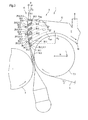
Die Figur 3 zeigt nunmehr eine schematische Seitenteilansicht einer Ausführungsform des erfindungsgemäßen Doppelsiebformers 1.FIG. 3 now shows a schematic partial side view of an embodiment of the twin-wire former 1 according to the invention.
Hinsichtlich des prinzipiellen Aufbaus dieses Doppelsiebformers 1 wird wiederum auf die Beschreibung des Doppelsiebformers 1 der Figur 1 verwiesen.With regard to the basic structure of this twin wire former 1 will turn refer to the description of the twin-wire former 1 of Figure 1.
Die Impingementeinrichfung 9 ist als ein Impingementschuh 9.1 ausgebildet, der
einen Belag 28 mit mehreren in Sieblaufrichtung S (Pfeil) nacheinander und vorzugsweise
parallel zueinander angeordneten Leisten 29.1 bis 29.6 mit dazwischen
liegenden freien Entwässerungsöffnungen 30.1 bis 30.5 aufweist, die mit einer
jeweils ortsfesten und offenen Oberfläche 31.1 bis 31.6 das umlaufende Sieb 3
berühren, und der einen umfassenden Kasten 32 aufweist, dessen Kastenboden
33 derart dicht an der in Sieblaufrichtung S (Pfeil) vorgeordneten Brustwalze 7.1
angeordnet ist, dass der Kastenboden 33 zumindest bereichsweise um die Brustwalze
7.1 herumgeführt ist. Die in der Figur 1 dargestellte Anzahl von Leisten
weist lediglich exemplarischen Charakter auf; es können selbstverständlich mehr
oder auch weniger Leisten ihre Verwendung finden. Die in Sieblaufrichtung S
(Pfeil) erste Leiste 29.1 ist zudem als eine bekannte Auflaufleiste zur Stützung des
Siebs 3 nach dem Strahlauftreffpunkt 143 abgebildet. The
Der Kastenboden 33 weist einen - in vertikaler Richtung gesehen - höchsten Punkt B auf, der um eine vertikale Höhe Hv im Bereich von 10 bis 700 mm, vorzugsweise von 100 bis 400 mm, über dem Beginn der in Sieblaufrichtung S (Pfeil) ersten freien Entwässerungsöffnung 30.1 liegt.The box bottom 33 has a - seen in the vertical direction - highest point B, by a vertical height H v in the range of 10 to 700 mm, preferably 100 to 400 mm, above the beginning of the S in the direction of wire direction S (arrow) first free Drainage opening 30.1 is located.
Die Leisten 29.1 bis 29.6 weisen auflaufseitige Abstreifkanten 34.1 bis 34.6 auf, wobei die in Sieblaufrichtung S (Pfeil) zweite Leiste 29.2 und deren nachfolgende Leiste 29.3 bis 29.6 eine jeweilige Leitfläche 35.2 bis 35.6 aufweist, deren geometrisch lineare Verlängerung V29.2 bis V29.6 den Kastenboden 33 innenseitig nicht berührt.The strips 29.1 to 29.6 have run-off side scraping edges 34.1 to 34.6, wherein in the direction of wire direction S (arrow) second strip 29.2 and their subsequent strip 29.3 to 29.6 a respective guide surface 35.2 to 35.6, the geometrically linear extension V 29.2 to V 29.6 the box bottom 33 not touched on the inside.
Die jeweilige Leitfläche 35.2 bis 35.6 ist bevorzugt unter einem Winkel α ≤ 80°, vorzugsweise ≤ 60°, zur jeweiligen Sieblaufrichtung S (Pfeil) angeordnet und die Leisten 29.1 bis 29.6 weisen eine Breite B29.1 bis B29.6 (lediglich Angabe der Breite B29.4) ≤ 150 mm, vorzugsweise ≤ 100 mm, insbesondere ≤ 60 mm, auf.The respective guide surface 35.2 to 35.6 is preferably arranged at an angle α ≤ 80 °, preferably ≤ 60 °, to the respective wire direction S (arrow) and the strips 29.1 to 29.6 have a width B 29.1 to B 29.6 (only giving the width B 29.4 ) ≤ 150 mm, preferably ≤ 100 mm, in particular ≤ 60 mm.
In Ergänzung und/oder als Alternative kann die offene Oberfläche 31 des Impingementschuhs 9.1 zudem unterbrochene, maschinenbreite und quer zur Sieblaufrichtung S (Pfeil) ausgerichtete Schlitze, in Sieblaufrichtung S (Pfeil) ausgerichtete Fischgrätchenschlitze, Bohrungen und/oder andersartig geformte Öffnungen, insbesondere Durchbrüche, aufweisen.In addition and / or as an alternative, the open surface 31 of the impingement shoe 9.1 also interrupted, machine width and transverse to Sieblaufrichtung S (arrow) aligned slots, aligned in the wire direction S (arrow) Herringbone slots, holes and / or differently shaped openings, in particular breakthroughs.
Weiterhin weist der Impingementschuh 9.1 zwei gekrümmte Bereiche B1, B2 mit vorzugsweise unterschiedlichen Längen L1, L2 auf, deren Radien R1, R2 in Sieblaufrichtung S (Pfeil) jeweils einen größeren Wert aufweisen. Der Radius R1 des ersten Bereichs B1 weist einen Wert im Bereich von 0,6 bis 4 m, vorzugsweise von 1 bis 2 m, und der Radius R2 des zweiten Bereichs B2 weist einen Wert im Bereich von 2 bis 5 m, vorzugsweise von 3 m, auf, wohingegen die Länge L1 des ersten Bereichs B1 einen Wert im Bereich von 15 bis 150 mm, vorzugsweise von 70 bis 120 mm, und die Länge L2 des zweiten Bereichs B2 einen Wert im Bereich von 90 bis 250 mm aufweist. Selbstverständlich können auch mehrere Bereiche mit genannten Eigenschaften vorhanden sein. Furthermore, the impingement shoe 9.1 has two curved regions B 1 , B 2 , preferably with different lengths L 1 , L 2 , whose radii R 1 , R 2 each have a greater value in the direction of wire run S (arrow). The radius R 1 of the first region B 1 has a value in the range of 0.6 to 4 m, preferably 1 to 2 m, and the radius R 2 of the second region B 2 has a value in the range of 2 to 5 m, 3 m, whereas the length L 1 of the first region B 1 has a value in the range of 15 to 150 mm, preferably 70 to 120 mm, and the length L 2 of the second region B 2 has a value in the region of 90 up to 250 mm. Of course, several areas with these properties may be present.
Die freien Entwässerungsöffnungen 30.1 bis 30.5 weisen zudem unterschiedliche Größen auf, die vorzugsweise in Sieblaufrichtung S (Pfeil) betragsmäßig abnehmen.The free drainage holes 30.1 to 30.5 also have different Sizes, which decrease in terms of amount preferably in Sieblaufrichtung S (arrow).
Überdies ist der Impingementschuh 9.1 mittels mindestens einer nicht näher dargestellten,
dem Fachmann jedoch bekannten Vakuumquelle mit einem Vakuum V
≥ 0,5 kPa, vorzugsweise ≥ 2 kPa, insbesondere ≥ 5 kPa, regel-/steuerbar besaugt
und auf der dem Impingementschuh 9.1 gegenüberliegenden Seite der Doppelsiebstrecke
15 sind mehrere Leisten 36 angeordnet, die in bekannter Weise flexibel
an das anliegende Sieb 4 anpressbar sind. Die flexibel anpressbaren Leisten
36 sind zumindest teilweise gegenüberliegend den freien Entwässerungsöffnungen
30.1 bis 30.5 angeordnet.Moreover, the impingement shoe 9.1 by means of at least one not shown,
However, the vacuum source known to the person skilled in the art with a vacuum V
≥ 0.5 kPa, preferably ≥ 2 kPa, in particular ≥ 5 kPa, regularly / controllably evacuated
and on the Impingementschuh 9.1 opposite side of the
Die beiden Siebe 3, 4 weisen eine jeweilige Siebgeschwindigkeit v ≥ 1.500 m/min,
vorzugsweise ≥ 1.700 m/min, auf und die Doppelsiebstrecke 15 ist unter einem
Winkel β von 0° bis 90° zur Horizontalen H angeordnet. Der erfindungsgemäße
Doppelsiebformer 1 kann also als Horizontal-, als Vertikal- oder als Schrägformer
ausgebildet sein.The two
Zusammenfassend ist festzuhalten, dass durch die Erfindung ein Blattbildungssystem einer Maschine zur Herstellung einer fleckenfreien Faserstoffbahn mit einer sehr guten Formation auch bei hohen Geschwindigkeiten geschaffen wird. In summary, it should be noted that by the invention, a sheet forming system a machine for producing a stain-free fibrous web with a very good formation even at high speeds is created.
- 11
- Doppelsiebformertwin
- 22
- FaserstoffbahnFibrous web
- 3, 43, 4
- Siebscree
- 5, 65, 6
- Umfangsbereichperipheral region
- 7, 87, 8
- Umlenkelementdeflecting
- 7.1, 8.17.1, 8.1
- Brustwalzebreast roll
- 99
- ImpingementeinrichtungImpingementeinrichtung
- 1010
- StoffeinlaufspaltStock inlet gap
- 1111
- Stoffauflaufheadbox
- 1212
- FaserstoffsuspensionsstrahlFibrous suspension beam
- 1313
- FaserstoffsuspensionFibrous suspension
- 143, 144 14 3 , 14 4
- Strahlauftreffpunktbeam spot
- 1515
- Doppelsiebstrecketwin-wire
- 1616
- Formier- und EntwässerungselementeForming and drainage elements
- 17.1 bis 17.417.1 to 17.4
- Keramikleisteceramic bar
- 1818
- Kastenbox
- 1919
- Oberflächesurface
- 2020
- Auflaufleistebaking tray
- 2121
- Luftair
- 2222
- Wassersumpfwater swamp
- 2323
- Keramikleisteceramic bar
- 2424
- FoilrilleFoilrille
- 2525
- Leiteinrichtungguide
- 25.125.1
- Leitblechbaffle
- 2626
- Kastenbox
- 27.1 bis 27.327.1 to 27.3
- Keramikleisteceramic bar
- 2828
- Belagcovering
- 29.1 bis 29.629.1 to 29.6
- Leistestrip
- 29.129.1
- Erste Leiste First bar
- 30.1 bis 30.530.1 to 30.5
- Entwässerungsöffnungdrainage opening
- 30.130.1
- Erste EntwässerungsöffnungFirst drainage opening
- 31, 31.1 bis 31.631, 31.1 to 31.6
- Oberflächesurface
- 3232
- Kastenbox
- 3333
- Kastenbodenbox bottom
- 34.1 bis 34.634.1 to 34.6
- Abstreifkantestripping
- 35.2 bis 35.635.2 to 35.6
- Leitflächebaffle
- 3636
- Leistestrip
- BB
- PunktPoint
- B1, B2 B 1, B 2
- BereichArea
- B29.1 bis B29.6 B 29.1 to B 29.6
- Breitewidth
- cc
- Mittlere FeststoffkonzentrationAverage solids concentration
- HV H V
- Vertikale HöheVertical height
- L1, L2 L 1 , L 2
- Längelength
- R1, R2 R 1 , R 2
- Radiusradius
- SS
- Sieblaufrichtung (Pfeil)Sieblaufrichtung (arrow)
- VV
- Vakuumvacuum
- vv
- Siebgeschwindigkeit (Pfeil)Sieving speed (arrow)
- V29.2 bis V29.6 V 29.2 to V 29.6
- Verlängerungrenewal
- αα
- Winkel (Leitfläche)Angle (guide surface)
- ββ
- Winkel (Doppelsiebstrecke)Angle (twin-wire)
Claims (15)
dadurch gekennzeichnet, dass die Impingementeinrichtung (9) als ein Impingementschuh (9.1) ausgebildet ist, der einen Belag (28) mit mehreren in Sieblaufrichtung (S) nacheinander angeordneten Leisten (29.1 bis 29.6) mit dazwischen liegenden freien Entwässerungsöffnungen (30.1 bis 30.5) aufweist, die mit einer jeweils ortsfesten und offenen Oberfläche (31.1 bis 31.6) das umlaufende Sieb (3) berühren, und der einen umfassenden Kasten (32) aufweist, dessen Kastenboden (33) derart dicht an der in Sieblaufrichtung (S) vorgeordneten Brustwalze (7.1) angeordnet ist, dass der Kastenboden (33) zumindest bereichsweise um die Brustwalze (7.1) herumgeführt ist. Double-wire former (1) of a machine for producing a fibrous web (2), in particular a paper or board web, with two continuous endless screens (3, 4), both over a peripheral region (5, 6) of a respective deflecting element (7, 8) , in particular a breast roll (7.1, 8.1), which then at least until reaching an impingement device (9, 9.1) to form a wedge-shaped material inlet gap (10), which immediately at least one of a headbox (11) as a pulp suspension jet (12). discharged pulp suspension (13) on formation of respective Strahlauftreffpunkte (14 3 , 14 4 ) on the two wires (3, 4) receives, converge and then form a Doppelsiebstrecke (15), in which the two wires (3, 4) and the at least one intermediate fibrous suspension (13) is guided over a plurality of forming and drainage elements (16),
characterized in that the impingement device (9) as an impingement shoe (9.1) is formed, which has a covering (28) with a plurality in Sieblaufrichtung (S) successively arranged strips (29.1 to 29.6) with intermediate free drainage openings (30.1 to 30.5) with a respective stationary and open surface (31.1 to 31.6) touching the circumferential sieve (3), and having a comprehensive box (32), the box bottom (33) so close to the in the wire direction (S) upstream breast roll (7.1 ) is arranged, that the box bottom (33) is at least partially guided around the breast roll (7.1).
dadurch gekennzeichnet, dass der Kastenboden (33) einen - in vertikaler Richtung gesehen - höchsten Punkt (B) aufweist, der um eine vertikale Höhe (Hv) im Bereich von 10 bis 700 mm, vorzugsweise von 100 bis 400 mm, über dem Beginn der in Sieblaufrichtung (S) ersten freien Entwässerungsöffnung (30.1) liegt.Twin-wire former (1) according to claim 1,
characterized in that the box bottom (33) has a - seen in the vertical direction - highest point (B) by a vertical height (H v ) in the range of 10 to 700 mm, preferably from 100 to 400 mm, over the beginning the first free drainage opening (30.1) lies in the direction of the wire run (S).
dadurch gekennzeichnet, dass die Leisten (29.1 bis 29.6) auflaufseitige Abstreifkanten (34.1 bis 34.6) aufweisen, wobei die in Sieblaufrichtung (S) zweite und derer nachfolgende Leiste eine jeweilige Leitfläche (35.2 bis 35.6) aufweist, deren geometrisch lineare Verlängerung (V29.2 bis V29.6) den Kastenboden (33) innenseitig nicht berührt.Twin-wire former (1) according to claim 1 or 2,
characterized in that the strips (29.1 to 29.6) have runoff-side scraping edges (34.1 to 34.6), wherein the second strip in the wire direction (S) and the subsequent strip has a respective guide surface (35.2 to 35.6) whose geometrically linear extension (V 29.2 to V 29.6 ) does not touch the box bottom (33) on the inside.
dadurch gekennzeichnet, dass die jeweilige Leitfläche (35.2 bis 35.6) unter einem Winkel (α) ≤ 80°, vorzugsweise ≤ 60°, zur jeweiligen Sieblaufrichtung (S) angeordnet ist.Twin-wire former (1) according to claim 3,
characterized in that the respective guide surface (35.2 to 35.6) at an angle (α) ≤ 80 °, preferably ≤ 60 °, to the respective Sieblaufrichtung (S) is arranged.
dadurch gekennzeichnet, dass die Leisten (29.1 bis 29.6) eine Breite (B29.1 bis B29.6) ≤ 150 mm, vorzugsweise ≤ 100 mm, insbesondere kleiner ≤ 60 mm, aufweisen.Twin-wire former (1) according to one of the preceding claims,
characterized in that the strips (29.1 to 29.6) have a width (B 29.1 to B 29.6 ) ≤ 150 mm, preferably ≤ 100 mm, in particular smaller ≤ 60 mm.
dadurch gekennzeichnet, dass die offene Oberfläche (31) des Impingementschuhs (9.1) zudem unterbrochene, maschinenbreite und quer zur Sieblaufrichtung (S) ausgerichtete Schlitze, in Sieblaufrichtung (S) ausgerichtete Fischgrätchenschlitze, Bohrungen und/oder durch andersartig geformte Öffnungen aufweist. Twin-wire former (1) according to claim 1 or 2,
characterized in that the open surface (31) of the Impingementschuhs (9.1) also interrupted, machine width and transverse to the wire direction (S) aligned slits, in Sieblaufrichtung (S) aligned herringbone slots, holes and / or by differently shaped openings.
dadurch gekennzeichnet, dass der Impingementschuh (9.1) mindestens eine, vorzugsweise zwei oder mehrere gekrümmte Bereiche (B1, B2) mit vorzugsweise unterschiedlichen Längen (L1, L2) aufweist, deren Radien (R1, R2) in Sieblaufrichtung (S) jeweils einen größeren Wert aufweisen.Twin-wire former (1) according to one of the preceding claims,
characterized in that the impingement shoe (9.1) has at least one, preferably two or more curved regions (B 1 , B 2 ) with preferably different lengths (L 1 , L 2 ), the radii (R 1 , R 2 ) in the direction of wire direction ( S) each have a greater value.
dadurch gekennzeichnet, dass der Radius (R1) des ersten Bereichs (B1) einen Wert im Bereich von 0,6 bis 4 m, vorzugsweise von 1 bis 2 m, und der Radius (R2) des zweiten Bereichs (B2) einen Wert im Bereich von 2 bis 5 m, vorzugsweise von 3 m, aufweist.Twin-wire former (1) according to claim 7,
characterized in that the radius (R 1 ) of the first region (B 1 ) has a value in the range of 0.6 to 4 m, preferably 1 to 2 m, and the radius (R 2 ) of the second region (B 2 ) has a value in the range of 2 to 5 m, preferably 3 m.
dadurch gekennzeichnet, dass die Länge (L1) des ersten Bereichs (B1) einen Wert im Bereich von 15 bis 150 mm, vorzugsweise von 70 bis 120 mm, und die Länge (L2) des zweiten Bereichs (B2) einen Wert im Bereich von 90 bis 250 mm aufweist.Twin-wire former (1) according to claim 7 or 8,
characterized in that the length (L 1 ) of the first region (B 1 ) has a value in the range of 15 to 150 mm, preferably 70 to 120 mm, and the length (L 2 ) of the second region (B 2 ) a value in the range of 90 to 250 mm.
dadurch gekennzeichnet, dass die freien Entwässerungsöffnungen (30.1 bis 30.5) unterschiedliche Größen aufweisen, die vorzugsweise in Sieblaufrichtung (S) betragsmäßig abnehmen.Twin-wire former (1) according to one of the preceding claims,
characterized in that the free drainage openings (30.1 to 30.5) have different sizes, which decrease in terms of amount, preferably in the direction of wire run (S).
dadurch gekennzeichnet, dass der Impingementschuh (9.1) mittels mindestens einer Vakuumquelle mit einem Vakuum (V) ≥ 0,5 kPa, vorzugsweise ≥ 2 kPa, insbesondere ≥ 5 kPa, regel-/steuerbar besaugt ist. Twin-wire former (1) according to one of the preceding claims,
characterized in that the impingement shoe (9.1) by means of at least one vacuum source with a vacuum (V) ≥ 0.5 kPa, preferably ≥ 2 kPa, in particular ≥ 5 kPa, is regularly / controllably sucked.
dadurch gekennzeichnet, dass auf der dem Impingementschuh (9.1) gegenüber liegenden Seite der Doppelsiebstrecke (15) mehrere Leisten (36) angeordnet sind, die flexibel an das anliegende Sieb (4) anpressbar sind.Twin-wire former (1) according to one of the preceding claims,
characterized in that on the impingement shoe (9.1) opposite side of the Doppelsiebstrecke (15) a plurality of strips (36) are arranged, which are flexible to the adjacent sieve (4) can be pressed.
dadurch gekennzeichnet, dass die flexibel anpressbaren (36) Leisten zumindest teilweise gegenüberliegend den freien Entwässerungsöffnungen (30.1 bis 30.5) angeordnet sind.Twin-wire former (1) according to claim 12,
characterized in that the flexibly compressible (36) strips at least partially opposite the free drainage openings (30.1 to 30.5) are arranged.
dadurch gekennzeichnet, dass die beiden Siebe (3, 4) eine jeweilige Siebgeschwindigkeit (v) ≥ 1.500 m/min, vorzugsweise ≥ 1.700 m/min, aufweisen.Twin-wire former (1) according to one of the preceding claims,
characterized in that the two screens (3, 4) have a respective screen speed (v) ≥ 1,500 m / min, preferably ≥ 1,700 m / min.
dadurch gekennzeichnet, dass die Doppelsiebstrecke (15) unter einem Winkel (β) von 0° bis 90° zur Horizontalen (H) angeordnet ist.Twin-wire former (1) according to one of the preceding claims,
characterized in that the Doppelsiebstrecke (15) at an angle (β) of 0 ° to 90 ° to the horizontal (H) is arranged.
Applications Claiming Priority (2)
| Application Number | Priority Date | Filing Date | Title |
|---|---|---|---|
| DE102004018329A DE102004018329A1 (en) | 2004-04-13 | 2004-04-13 | Twin-wire former of a machine for producing a fibrous web |
| DE102004018329 | 2004-04-13 |
Publications (2)
| Publication Number | Publication Date |
|---|---|
| EP1586702A1 true EP1586702A1 (en) | 2005-10-19 |
| EP1586702B1 EP1586702B1 (en) | 2009-07-01 |
Family
ID=34939119
Family Applications (1)
| Application Number | Title | Priority Date | Filing Date |
|---|---|---|---|
| EP05102625A Not-in-force EP1586702B1 (en) | 2004-04-13 | 2005-04-04 | Twin-wire former for a machine for manufacturing a fibrous web |
Country Status (3)
| Country | Link |
|---|---|
| EP (1) | EP1586702B1 (en) |
| AT (1) | ATE435331T1 (en) |
| DE (2) | DE102004018329A1 (en) |
Cited By (2)
| Publication number | Priority date | Publication date | Assignee | Title |
|---|---|---|---|---|
| DE102008040948A1 (en) | 2008-08-01 | 2010-02-04 | Voith Patent Gmbh | Twin-wire former for a machine for producing a fibrous web |
| DE102010003320A1 (en) | 2010-03-26 | 2011-09-29 | Voith Patent Gmbh | Sheet forming system for a machine for producing a fibrous web and associated method |
Citations (4)
| Publication number | Priority date | Publication date | Assignee | Title |
|---|---|---|---|---|
| DE4141607A1 (en) * | 1991-12-17 | 1993-06-24 | Voith Gmbh J M | DOUBLE SCREEN FORMER |
| DE4208681A1 (en) * | 1992-03-18 | 1993-09-23 | Escher Wyss Gmbh | Double four drinker paper-making press section - has forming roller for lower four drinker at entry with water extn. unit and further forming roller at upper four drinker |
| DE19803451A1 (en) * | 1998-01-30 | 1999-08-05 | Voith Sulzer Papiertech Patent | Fourdrinier section of a paper and cardboard production machine |
| US20010025697A1 (en) * | 1999-06-18 | 2001-10-04 | Vaughn J. Wildfong | Method and apparatus for forming a paper web |
-
2004
- 2004-04-13 DE DE102004018329A patent/DE102004018329A1/en not_active Withdrawn
-
2005
- 2005-04-04 EP EP05102625A patent/EP1586702B1/en not_active Not-in-force
- 2005-04-04 DE DE502005007600T patent/DE502005007600D1/en active Active
- 2005-04-04 AT AT05102625T patent/ATE435331T1/en active
Patent Citations (4)
| Publication number | Priority date | Publication date | Assignee | Title |
|---|---|---|---|---|
| DE4141607A1 (en) * | 1991-12-17 | 1993-06-24 | Voith Gmbh J M | DOUBLE SCREEN FORMER |
| DE4208681A1 (en) * | 1992-03-18 | 1993-09-23 | Escher Wyss Gmbh | Double four drinker paper-making press section - has forming roller for lower four drinker at entry with water extn. unit and further forming roller at upper four drinker |
| DE19803451A1 (en) * | 1998-01-30 | 1999-08-05 | Voith Sulzer Papiertech Patent | Fourdrinier section of a paper and cardboard production machine |
| US20010025697A1 (en) * | 1999-06-18 | 2001-10-04 | Vaughn J. Wildfong | Method and apparatus for forming a paper web |
Cited By (5)
| Publication number | Priority date | Publication date | Assignee | Title |
|---|---|---|---|---|
| DE102008040948A1 (en) | 2008-08-01 | 2010-02-04 | Voith Patent Gmbh | Twin-wire former for a machine for producing a fibrous web |
| WO2010012676A2 (en) * | 2008-08-01 | 2010-02-04 | Voith Patent Gmbh | Twin-wire former for a machine for producing a web of fibrous material |
| WO2010012676A3 (en) * | 2008-08-01 | 2010-05-06 | Voith Patent Gmbh | Twin-wire former for a machine for producing a web of fibrous material |
| DE102010003320A1 (en) | 2010-03-26 | 2011-09-29 | Voith Patent Gmbh | Sheet forming system for a machine for producing a fibrous web and associated method |
| WO2011116999A1 (en) | 2010-03-26 | 2011-09-29 | Voith Patent Gmbh | Sheet forming system for a machine for producing a fibrous web, and associated method |
Also Published As
| Publication number | Publication date |
|---|---|
| DE502005007600D1 (en) | 2009-08-13 |
| ATE435331T1 (en) | 2009-07-15 |
| DE102004018329A1 (en) | 2005-11-10 |
| EP1586702B1 (en) | 2009-07-01 |
Similar Documents
| Publication | Publication Date | Title |
|---|---|---|
| DE3153305C2 (en) | Drainage unit for Fourdrinier paper machines | |
| EP0933473A2 (en) | Twin-wire former | |
| EP2739780B1 (en) | Sheet forming system for a machine for producing a two-layer or multi-layer web | |
| DE3131957A1 (en) | DRAINAGE UNIT FOR LONG SCREEN PAPER MACHINES | |
| DE69628490T2 (en) | Twin wire former for a paper machine with a dewatering device | |
| EP1586702B1 (en) | Twin-wire former for a machine for manufacturing a fibrous web | |
| WO2012000690A2 (en) | Sheet-forming system for a machine for producing an at least single-layer fibrous material web | |
| EP1370726B1 (en) | Twin wire former | |
| DE3107730A1 (en) | Double wire section | |
| EP1659211B1 (en) | Formation system of a machine for manufacturing a fibrous web | |
| DE60124739T2 (en) | STUFFED EDGE BUCKET FOR A PAPER MACHINE | |
| DE69923084T2 (en) | twin | |
| EP1424437A1 (en) | Twin-wire former | |
| AT524904B1 (en) | Edge limitation for a wire section | |
| EP4328376A1 (en) | Inclined screen former | |
| DE202005021804U1 (en) | Sheet forming system | |
| EP1489229B1 (en) | Twin-wire former of a machine for manufacturing a fibrous web | |
| DE102005000178A1 (en) | Double-sieve sheet formation system of paper- or card-making machine, includes air boundary layer scraper supported independently of suspension header box | |
| DE202004001935U1 (en) | Paper- or carton-making assembly has angular control of fibre suspension discharge jets as directed at impingement point on de-watering belt | |
| WO2010012676A2 (en) | Twin-wire former for a machine for producing a web of fibrous material | |
| DE10242564A1 (en) | Papermaking process has two de-watering sieve belts running back-to-back and tangentially deflected at the mid-point by a transverse wiper blade | |
| DE102011081312A1 (en) | Twin-wire former for a machine for producing a fibrous web from at least one pulp suspension | |
| EP2022890A1 (en) | Twin wire former for a production machine for fibrous sheets and method of manufacturing a fibrous sheet | |
| DE102005037643A1 (en) | Double sieve former for machine for producing fibrous sheet, e.g. of paper, from fiber suspension, has common dewatering element giving impulse-free initial dewatering and efficient subsequent dewatering | |
| EP1719835A1 (en) | Machine for manufacturing a fibrous web |
Legal Events
| Date | Code | Title | Description |
|---|---|---|---|
| PUAI | Public reference made under article 153(3) epc to a published international application that has entered the european phase |
Free format text: ORIGINAL CODE: 0009012 |
|
| AK | Designated contracting states |
Kind code of ref document: A1 Designated state(s): AT BE BG CH CY CZ DE DK EE ES FI FR GB GR HU IE IS IT LI LT LU MC NL PL PT RO SE SI SK TR |
|
| AX | Request for extension of the european patent |
Extension state: AL BA HR LV MK YU |
|
| 17P | Request for examination filed |
Effective date: 20060419 |
|
| AKX | Designation fees paid |
Designated state(s): AT BE BG CH CY CZ DE DK EE ES FI FR GB GR HU IE IS IT LI LT LU MC NL PL PT RO SE SI SK TR |
|
| RAP1 | Party data changed (applicant data changed or rights of an application transferred) |
Owner name: VOITH PATENT GMBH |
|
| 17Q | First examination report despatched |
Effective date: 20070702 |
|
| GRAP | Despatch of communication of intention to grant a patent |
Free format text: ORIGINAL CODE: EPIDOSNIGR1 |
|
| GRAS | Grant fee paid |
Free format text: ORIGINAL CODE: EPIDOSNIGR3 |
|
| GRAA | (expected) grant |
Free format text: ORIGINAL CODE: 0009210 |
|
| AK | Designated contracting states |
Kind code of ref document: B1 Designated state(s): AT BE BG CH CY CZ DE DK EE ES FI FR GB GR HU IE IS IT LI LT LU MC NL PL PT RO SE SI SK TR |
|
| REG | Reference to a national code |
Ref country code: GB Ref legal event code: FG4D Free format text: NOT ENGLISH |
|
| REG | Reference to a national code |
Ref country code: CH Ref legal event code: EP |
|
| REG | Reference to a national code |
Ref country code: IE Ref legal event code: FG4D |
|
| REF | Corresponds to: |
Ref document number: 502005007600 Country of ref document: DE Date of ref document: 20090813 Kind code of ref document: P |
|
| REG | Reference to a national code |
Ref country code: SE Ref legal event code: TRGR |
|
| PG25 | Lapsed in a contracting state [announced via postgrant information from national office to epo] |
Ref country code: SI Free format text: LAPSE BECAUSE OF FAILURE TO SUBMIT A TRANSLATION OF THE DESCRIPTION OR TO PAY THE FEE WITHIN THE PRESCRIBED TIME-LIMIT Effective date: 20090701 |
|
| NLV1 | Nl: lapsed or annulled due to failure to fulfill the requirements of art. 29p and 29m of the patents act | ||
| PG25 | Lapsed in a contracting state [announced via postgrant information from national office to epo] |
Ref country code: EE Free format text: LAPSE BECAUSE OF FAILURE TO SUBMIT A TRANSLATION OF THE DESCRIPTION OR TO PAY THE FEE WITHIN THE PRESCRIBED TIME-LIMIT Effective date: 20090701 Ref country code: IS Free format text: LAPSE BECAUSE OF FAILURE TO SUBMIT A TRANSLATION OF THE DESCRIPTION OR TO PAY THE FEE WITHIN THE PRESCRIBED TIME-LIMIT Effective date: 20091101 Ref country code: ES Free format text: LAPSE BECAUSE OF FAILURE TO SUBMIT A TRANSLATION OF THE DESCRIPTION OR TO PAY THE FEE WITHIN THE PRESCRIBED TIME-LIMIT Effective date: 20091012 Ref country code: LT Free format text: LAPSE BECAUSE OF FAILURE TO SUBMIT A TRANSLATION OF THE DESCRIPTION OR TO PAY THE FEE WITHIN THE PRESCRIBED TIME-LIMIT Effective date: 20090701 |
|
| REG | Reference to a national code |
Ref country code: IE Ref legal event code: FD4D |
|
| PG25 | Lapsed in a contracting state [announced via postgrant information from national office to epo] |
Ref country code: NL Free format text: LAPSE BECAUSE OF FAILURE TO SUBMIT A TRANSLATION OF THE DESCRIPTION OR TO PAY THE FEE WITHIN THE PRESCRIBED TIME-LIMIT Effective date: 20090701 Ref country code: PL Free format text: LAPSE BECAUSE OF FAILURE TO SUBMIT A TRANSLATION OF THE DESCRIPTION OR TO PAY THE FEE WITHIN THE PRESCRIBED TIME-LIMIT Effective date: 20090701 |
|
| PG25 | Lapsed in a contracting state [announced via postgrant information from national office to epo] |
Ref country code: BG Free format text: LAPSE BECAUSE OF FAILURE TO SUBMIT A TRANSLATION OF THE DESCRIPTION OR TO PAY THE FEE WITHIN THE PRESCRIBED TIME-LIMIT Effective date: 20091001 Ref country code: PT Free format text: LAPSE BECAUSE OF FAILURE TO SUBMIT A TRANSLATION OF THE DESCRIPTION OR TO PAY THE FEE WITHIN THE PRESCRIBED TIME-LIMIT Effective date: 20091102 |
|
| PG25 | Lapsed in a contracting state [announced via postgrant information from national office to epo] |
Ref country code: IE Free format text: LAPSE BECAUSE OF FAILURE TO SUBMIT A TRANSLATION OF THE DESCRIPTION OR TO PAY THE FEE WITHIN THE PRESCRIBED TIME-LIMIT Effective date: 20090701 Ref country code: RO Free format text: LAPSE BECAUSE OF FAILURE TO SUBMIT A TRANSLATION OF THE DESCRIPTION OR TO PAY THE FEE WITHIN THE PRESCRIBED TIME-LIMIT Effective date: 20090701 Ref country code: CZ Free format text: LAPSE BECAUSE OF FAILURE TO SUBMIT A TRANSLATION OF THE DESCRIPTION OR TO PAY THE FEE WITHIN THE PRESCRIBED TIME-LIMIT Effective date: 20090701 Ref country code: DK Free format text: LAPSE BECAUSE OF FAILURE TO SUBMIT A TRANSLATION OF THE DESCRIPTION OR TO PAY THE FEE WITHIN THE PRESCRIBED TIME-LIMIT Effective date: 20090701 |
|
| PLBE | No opposition filed within time limit |
Free format text: ORIGINAL CODE: 0009261 |
|
| STAA | Information on the status of an ep patent application or granted ep patent |
Free format text: STATUS: NO OPPOSITION FILED WITHIN TIME LIMIT |
|
| PG25 | Lapsed in a contracting state [announced via postgrant information from national office to epo] |
Ref country code: SK Free format text: LAPSE BECAUSE OF FAILURE TO SUBMIT A TRANSLATION OF THE DESCRIPTION OR TO PAY THE FEE WITHIN THE PRESCRIBED TIME-LIMIT Effective date: 20090701 |
|
| 26N | No opposition filed |
Effective date: 20100406 |
|
| PG25 | Lapsed in a contracting state [announced via postgrant information from national office to epo] |
Ref country code: GR Free format text: LAPSE BECAUSE OF FAILURE TO SUBMIT A TRANSLATION OF THE DESCRIPTION OR TO PAY THE FEE WITHIN THE PRESCRIBED TIME-LIMIT Effective date: 20091002 |
|
| BERE | Be: lapsed |
Owner name: VOITH PATENT G.M.B.H. Effective date: 20100430 |
|
| PG25 | Lapsed in a contracting state [announced via postgrant information from national office to epo] |
Ref country code: MC Free format text: LAPSE BECAUSE OF NON-PAYMENT OF DUE FEES Effective date: 20100430 |
|
| REG | Reference to a national code |
Ref country code: CH Ref legal event code: PL |
|
| GBPC | Gb: european patent ceased through non-payment of renewal fee |
Effective date: 20100404 |
|
| PG25 | Lapsed in a contracting state [announced via postgrant information from national office to epo] |
Ref country code: LI Free format text: LAPSE BECAUSE OF NON-PAYMENT OF DUE FEES Effective date: 20100430 Ref country code: CH Free format text: LAPSE BECAUSE OF NON-PAYMENT OF DUE FEES Effective date: 20100430 |
|
| PG25 | Lapsed in a contracting state [announced via postgrant information from national office to epo] |
Ref country code: GB Free format text: LAPSE BECAUSE OF NON-PAYMENT OF DUE FEES Effective date: 20100404 Ref country code: BE Free format text: LAPSE BECAUSE OF NON-PAYMENT OF DUE FEES Effective date: 20100430 |
|
| PGFP | Annual fee paid to national office [announced via postgrant information from national office to epo] |
Ref country code: SE Payment date: 20110414 Year of fee payment: 7 Ref country code: FR Payment date: 20110510 Year of fee payment: 7 |
|
| PGFP | Annual fee paid to national office [announced via postgrant information from national office to epo] |
Ref country code: IT Payment date: 20110419 Year of fee payment: 7 |
|
| PG25 | Lapsed in a contracting state [announced via postgrant information from national office to epo] |
Ref country code: CY Free format text: LAPSE BECAUSE OF FAILURE TO SUBMIT A TRANSLATION OF THE DESCRIPTION OR TO PAY THE FEE WITHIN THE PRESCRIBED TIME-LIMIT Effective date: 20090701 |
|
| PG25 | Lapsed in a contracting state [announced via postgrant information from national office to epo] |
Ref country code: LU Free format text: LAPSE BECAUSE OF NON-PAYMENT OF DUE FEES Effective date: 20100404 Ref country code: HU Free format text: LAPSE BECAUSE OF FAILURE TO SUBMIT A TRANSLATION OF THE DESCRIPTION OR TO PAY THE FEE WITHIN THE PRESCRIBED TIME-LIMIT Effective date: 20100102 |
|
| PG25 | Lapsed in a contracting state [announced via postgrant information from national office to epo] |
Ref country code: TR Free format text: LAPSE BECAUSE OF FAILURE TO SUBMIT A TRANSLATION OF THE DESCRIPTION OR TO PAY THE FEE WITHIN THE PRESCRIBED TIME-LIMIT Effective date: 20090701 |
|
| REG | Reference to a national code |
Ref country code: SE Ref legal event code: EUG |
|
| REG | Reference to a national code |
Ref country code: FR Ref legal event code: ST Effective date: 20121228 |
|
| PG25 | Lapsed in a contracting state [announced via postgrant information from national office to epo] |
Ref country code: SE Free format text: LAPSE BECAUSE OF NON-PAYMENT OF DUE FEES Effective date: 20120405 Ref country code: IT Free format text: LAPSE BECAUSE OF NON-PAYMENT OF DUE FEES Effective date: 20120404 Ref country code: FR Free format text: LAPSE BECAUSE OF NON-PAYMENT OF DUE FEES Effective date: 20120430 |
|
| PGFP | Annual fee paid to national office [announced via postgrant information from national office to epo] |
Ref country code: AT Payment date: 20120411 Year of fee payment: 8 |
|
| PGFP | Annual fee paid to national office [announced via postgrant information from national office to epo] |
Ref country code: DE Payment date: 20130419 Year of fee payment: 9 |
|
| PGFP | Annual fee paid to national office [announced via postgrant information from national office to epo] |
Ref country code: FI Payment date: 20130411 Year of fee payment: 9 |
|
| REG | Reference to a national code |
Ref country code: DE Ref legal event code: R119 Ref document number: 502005007600 Country of ref document: DE |
|
| REG | Reference to a national code |
Ref country code: AT Ref legal event code: MM01 Ref document number: 435331 Country of ref document: AT Kind code of ref document: T Effective date: 20140404 |
|
| REG | Reference to a national code |
Ref country code: DE Ref legal event code: R119 Ref document number: 502005007600 Country of ref document: DE Effective date: 20141101 |
|
| PG25 | Lapsed in a contracting state [announced via postgrant information from national office to epo] |
Ref country code: DE Free format text: LAPSE BECAUSE OF NON-PAYMENT OF DUE FEES Effective date: 20141101 Ref country code: FI Free format text: LAPSE BECAUSE OF NON-PAYMENT OF DUE FEES Effective date: 20140404 |
|
| PG25 | Lapsed in a contracting state [announced via postgrant information from national office to epo] |
Ref country code: AT Free format text: LAPSE BECAUSE OF NON-PAYMENT OF DUE FEES Effective date: 20140404 |