EP1586245A1 - Förderanordnung für eine Maschine der tabakverarbeitenden Industrie - Google Patents
Förderanordnung für eine Maschine der tabakverarbeitenden Industrie Download PDFInfo
- Publication number
- EP1586245A1 EP1586245A1 EP05090106A EP05090106A EP1586245A1 EP 1586245 A1 EP1586245 A1 EP 1586245A1 EP 05090106 A EP05090106 A EP 05090106A EP 05090106 A EP05090106 A EP 05090106A EP 1586245 A1 EP1586245 A1 EP 1586245A1
- Authority
- EP
- European Patent Office
- Prior art keywords
- conveying
- conveyor
- arrangement according
- nozzle
- medium
- Prior art date
- Legal status (The legal status is an assumption and is not a legal conclusion. Google has not performed a legal analysis and makes no representation as to the accuracy of the status listed.)
- Granted
Links
- 241000208125 Nicotiana Species 0.000 title claims abstract description 13
- 235000002637 Nicotiana tabacum Nutrition 0.000 title claims abstract description 13
- 230000003750 conditioning effect Effects 0.000 claims description 10
- 239000000203 mixture Substances 0.000 claims description 5
- 239000007788 liquid Substances 0.000 claims description 3
- XLYOFNOQVPJJNP-UHFFFAOYSA-N water Chemical compound O XLYOFNOQVPJJNP-UHFFFAOYSA-N 0.000 claims description 3
- 238000007664 blowing Methods 0.000 claims description 2
- 230000001737 promoting effect Effects 0.000 abstract 1
- 235000019505 tobacco product Nutrition 0.000 description 7
- 230000000694 effects Effects 0.000 description 5
- 239000000835 fiber Substances 0.000 description 5
- 238000000926 separation method Methods 0.000 description 4
- 238000001035 drying Methods 0.000 description 3
- 239000007789 gas Substances 0.000 description 3
- IJGRMHOSHXDMSA-UHFFFAOYSA-N Atomic nitrogen Chemical compound N#N IJGRMHOSHXDMSA-UHFFFAOYSA-N 0.000 description 2
- CURLTUGMZLYLDI-UHFFFAOYSA-N Carbon dioxide Chemical compound O=C=O CURLTUGMZLYLDI-UHFFFAOYSA-N 0.000 description 2
- LYCAIKOWRPUZTN-UHFFFAOYSA-N Ethylene glycol Chemical compound OCCO LYCAIKOWRPUZTN-UHFFFAOYSA-N 0.000 description 2
- 239000000463 material Substances 0.000 description 2
- 229910002092 carbon dioxide Inorganic materials 0.000 description 1
- 239000001569 carbon dioxide Substances 0.000 description 1
- 238000004140 cleaning Methods 0.000 description 1
- 230000001419 dependent effect Effects 0.000 description 1
- 238000000151 deposition Methods 0.000 description 1
- 238000000265 homogenisation Methods 0.000 description 1
- 239000003906 humectant Substances 0.000 description 1
- WGCNASOHLSPBMP-UHFFFAOYSA-N hydroxyacetaldehyde Natural products OCC=O WGCNASOHLSPBMP-UHFFFAOYSA-N 0.000 description 1
- 229910052757 nitrogen Inorganic materials 0.000 description 1
- 235000015067 sauces Nutrition 0.000 description 1
- 238000010008 shearing Methods 0.000 description 1
- 239000007787 solid Substances 0.000 description 1
- 238000005507 spraying Methods 0.000 description 1
Images
Classifications
-
- A—HUMAN NECESSITIES
- A24—TOBACCO; CIGARS; CIGARETTES; SIMULATED SMOKING DEVICES; SMOKERS' REQUISITES
- A24B—MANUFACTURE OR PREPARATION OF TOBACCO FOR SMOKING OR CHEWING; TOBACCO; SNUFF
- A24B3/00—Preparing tobacco in the factory
- A24B3/04—Humidifying or drying tobacco bunches or cut tobacco
Definitions
- the invention relates to a conveyor arrangement for a machine of tobacco processing Industrial, with a conveying device, a plurality of themselves in a conveying direction moving conveyor elements for conveying and / or singulating a fibrous Product has.
- From DE 100 08 961 A1 is a separating device with rotating rake known, being arranged on the circumference of the formed as a hollow pins computing tines Air nozzles blow air jets escape to the distribution effect of the rake tines to reinforce.
- the object of the present invention is to provide a conveyor arrangement, with the improved separation of the product fibers can be achieved.
- the invention solves this problem in particular by the fact that the conveyor assembly in Area of the conveying elements at least one fixed nozzle for blowing a Medium in the opposite direction to the conveying direction.
- the injected medium exerts a separation of the product fibers causing shearing forces on that of the conveyor elements taken away product.
- the injected medium can be a gas stream, in particular of air, water vapor or a mixture thereof, or another suitable medium.
- the medium for spraying a conditioning medium in liquid or gaseous form or a mixture thereof for the product serve.
- a preferred conditioning medium is water vapor.
- Other possible conditioning media For example, carbon dioxide is used in the tobacco industry Flavorings, sauces consisting of solids dissolved in liquid such as Sugar, humectants such as glycol, or pure gases such as Nitrogen, or a mixture of these media.
- the conveyor may serve to convey or singulate the product.
- the term conveying device therefore also includes a separating device whose Main function in the separation of the product fibers lies.
- the conveying direction is at a rotating conveyor usually the circumferential direction.
- the exit direction of the The medium emerging from the nozzle is therefore essentially counter to this circumferential direction directed.
- the arrangement of the nozzle in the region of the conveying elements means that from the nozzle escaping medium essentially on the entrained by the conveyor elements Product meets.
- the nozzle is in the region of a free end of the conveying elements arranged to remove the product from the conveyor elements to blow off and thereby improve the separating effect.
- Fixed nozzle means relative to the conveyor assembly or to a conveyor surrounding housing fixed.
- the invention is delimited to nozzle openings in the moving conveyor elements themselves, as in the DE 100 08 961 A1, or in itself with the conveying elements moving parts of the conveyor, such as the nozzles in the roll body of the Winnover roll according to EP 0 895 721 B1.
- These known nozzles are not suitable, the inventive To achieve the dicing effect of tobacco fibers.
- the invention fixed nozzle can be arranged on a housing surrounding the conveyor be; however, this is not necessarily the case.
- the invention is not on rotating conveyors limited. It is also conceivable, for example, the application to a linear Conveyor, such as a belt conveyor, with extending over the width of the belt Feeder rakes. Preference is furthermore the application of the invention to a as Conditioning device for applying a conditioning medium to the product trained conveyor.
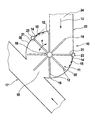
- a conveyor assembly 10 includes a closed conveyor channel 22 for conveying a tobacco product entering at 24 through the opening 18 in a current dryer 17.
- a conveying device in the form of a rotating Winnover roller 11 arranged.
- On the roller body 16 axial rows are tine-shaped arranged radial pins 12 which form rotating rake to the tobacco product 13 foundedlockern by mechanical action or to separate.
- the direction of rotation The Winnoverwalze 11 therefore forms the conveying direction F of the tobacco product 13 in Range of Winnoverwalze 11.
- the roller body 16 and / or the pins 12 can hollow and with nozzle openings for applying a conditioning medium be provided on the tobacco product, as in EP 0 895 721 B1 and DE 100 08 961 A1 is described.
- the Winnover roller 11 is of a part of the conveying channel 22 forming housing 20 surrounded.
- nozzles 14 are arranged, through which a gas flow 15th is injected substantially tangentially into the interior of the housing 20.
- the illustrated two nozzles 14 may also only one or a plurality of nozzles 14 may be provided along the circumference of the Winnoverwalze 11.
- the nozzles 14 can as a nozzle bar, i. in an over the axial width of the Winnoverwalze 11 extending, axially parallel nozzle channel 23 may be formed. It can be a A plurality of nozzles 14 extending across the nozzle channel 23 or one or more elongate, over the nozzle channel 23 extending nozzles 14 act.
- the nozzle channel 23 is applied, for example, with compressed air, so that from the nozzles 14th Exiting air forms an air flow 15, which is approximately tangential to the envelope or the fictitious outer circumference of the Winnoverwalze 11 and therefore approximately opposite Conveying direction F is oriented.
- the air flow 15 is substantially in the in Fig. 1st Dashed area shown directed, for example, an opening angle of May have 15 °.
- Guiding means 21 for example guide plates, provided at the opening of the nozzles 14 be; however, this is not mandatory.
- the air flow 15 meets the particular from the free ends 19 of the pins 12 entrained tobacco product 13 and exercises on this shear forces, the a loosening, separation and homogenization cause the fibers of the tobacco product 13. This allows a more even Drying of the tobacco product 13 in the flow dryer 17 and thereby an improved Drying result can be achieved.
- the air flow 15 passes along the inner wall of the housing 20 along and prevents thereby depositing tobacco material on the inner wall of the housing 20, thereby as a further advantage of the invention downtime due to required cleaning the inner wall of the housing 20 can be reduced.
Landscapes
- Manufacture Of Tobacco Products (AREA)
- Manufacturing Of Cigar And Cigarette Tobacco (AREA)
- Intermediate Stations On Conveyors (AREA)
- Wrapping Of Specific Fragile Articles (AREA)
- Drying Of Solid Materials (AREA)
Abstract
Description
Claims (11)
- Förderanordnung (10) für eine Maschine der tabakverarbeitenden Industrie, mit einer Fördervorrichtung (11), die eine Mehrzahl von sich in einer Förderrichtung (F) bewegenden Förderelementen (12) zum Fördern und/oder Vereinzeln eines faset-förmigen Produkts (13) aufweist, dadurch gekennzeichnet, dass die Förderanordnung (10) im Bereich der Förderelemente (12) mindestens eine feststehende Düse (14) zum Einblasen eines Mediums (15) in Gegenrichtung zu der Fördernchtung (F) aufweist.
- Förderanordnung nach Anspruch 1, dadurch gekennzeichnet, dass die Fördervorrichtung (11) rotierend mit sich radial erstreckenden Förderelementen (12) ausgebildet ist.
- Förderanordnung nach Anspruch 2, dadurch gekennzeichnet, dass die rotierende Fördervorrichtung (11) eine am Tabakeinlaß eines Stromtrockners (17) angeordnete Winnoverwalze ist.
- Förderanordnung nach Anspruch 2 oder 3, dadurch gekennzeichnet, dass die Düse (14) so angeordnet ist, dass die Eintrittsrichtung des Mediums (15) etwa tangential zu dem fiktiven Außenumfang der rotierenden Fördervorrichtung (11) orientiert ist.
- Förderanordnung nach einem der Ansprüche 1 bis 4, dadurch gekennzeichnet, dass die Düse (14) an einem die Fördervorrichtung (11) umgebenden Gehäuse (20) angeordnet ist.
- Förderanordnung nach einem der Ansprüche 1 bis 5, dadurch gekennzeichnet, dass die Düse (14) als Düsenleiste ausgebildet ist.
- Förderanordnung nach einem der Ansprüche 1 bis 6, dadurch gekennzeichnet, dass die Förderelemente (12) stiftförmig sind.
- Förderanordnung nach einem der Ansprüche 1 bis 7, dadurch gekennzeichnet, dass die Düse (14) im Bereich eines freien Endes (19) der Förderelemente (12) angeordnet ist.
- Förderanordnung nach einem der Ansprüche 1 bis 8, dadurch gekennzeichnet, dass das Medium (15) eine gasförmige Komponente vorzugsweise aus Luft, Wasserdampf oder einer Mischung daraus umfasst.
- Förderanordnung nach einem der Ansprüche 1 bis 9, dadurch gekennzeichnet, dass das Medium (15) ein Konditioniermedium in flüssiger oder gasförmiger Form oder einer Mischung daraus enthält.
- Förderanordnung nach einem der Ansprüche 1 bis 10, dadurch gekennzeichnet, dass die Fördervorrichtung eine Konditioniervorrichtung zum Aufbringen eines Konditioniermediums auf das Produkt ist.
Priority Applications (1)
| Application Number | Priority Date | Filing Date | Title |
|---|---|---|---|
| PL05090106T PL1586245T3 (pl) | 2004-04-15 | 2005-04-15 | Układ transportowy maszyny stosowanej w przemyśle tytoniowym |
Applications Claiming Priority (2)
| Application Number | Priority Date | Filing Date | Title |
|---|---|---|---|
| DE102004018879A DE102004018879A1 (de) | 2004-04-15 | 2004-04-15 | Förderanordnung für eine Maschine der tabakverarbeitenden Industrie |
| DE102004018879 | 2004-04-15 |
Publications (2)
| Publication Number | Publication Date |
|---|---|
| EP1586245A1 true EP1586245A1 (de) | 2005-10-19 |
| EP1586245B1 EP1586245B1 (de) | 2008-05-07 |
Family
ID=34938437
Family Applications (1)
| Application Number | Title | Priority Date | Filing Date |
|---|---|---|---|
| EP05090106A Expired - Lifetime EP1586245B1 (de) | 2004-04-15 | 2005-04-15 | Förderanordnung für eine Maschine der tabakverarbeitenden Industrie |
Country Status (7)
| Country | Link |
|---|---|
| US (1) | US20050229940A1 (de) |
| EP (1) | EP1586245B1 (de) |
| CN (1) | CN1682612B (de) |
| AT (1) | ATE394038T1 (de) |
| BR (1) | BRPI0501319A (de) |
| DE (2) | DE102004018879A1 (de) |
| PL (1) | PL1586245T3 (de) |
Cited By (1)
| Publication number | Priority date | Publication date | Assignee | Title |
|---|---|---|---|---|
| EP2042045A1 (de) * | 2007-09-24 | 2009-04-01 | International Tobacco Machinery Poland Ltd | Verfahren und Zufuhrvorrichtung zum Erhöhen der Effizienz des Expansions- und Trocknungsverfahrens von organischen Pflanzenmaterialien, insbesondere in einem Düsentrockner |
Families Citing this family (1)
| Publication number | Priority date | Publication date | Assignee | Title |
|---|---|---|---|---|
| DE102006024936B3 (de) * | 2006-05-23 | 2007-10-11 | Hauni Maschinenbau Ag | Stromtrockner zum Trocknen eines faserförmigen Tabakprodukts |
Citations (7)
| Publication number | Priority date | Publication date | Assignee | Title |
|---|---|---|---|---|
| GB359999A (en) * | 1930-02-13 | 1931-10-26 | Bayuk Cigars Inc | Method and apparatus for treating tobacco |
| FR1251629A (fr) * | 1960-03-17 | 1961-01-20 | Arenco Ab | Appareil de séchage pour tabac ou matières analogues |
| US4791942A (en) * | 1986-08-01 | 1988-12-20 | The American Tobacco Company | Process and apparatus for the expansion of tobacco |
| US4967769A (en) * | 1988-03-04 | 1990-11-06 | Gbe International Plc | Combined feeder/conditioner |
| EP0514860A2 (de) * | 1991-05-20 | 1992-11-25 | Japan Tobacco Inc. | Aufblähvorrichtung für ein landwirtschaftliches Produkt, wie Tabakmaterial |
| EP0895721A1 (de) * | 1997-08-08 | 1999-02-10 | Hauni Maschinenbau Aktiengesellschaft | Verfahren und Vorrichtung zum Aufbringen eines Konditionierungsmediums auf Tabakmaterial |
| US20020033182A1 (en) * | 2000-08-04 | 2002-03-21 | Ehling Uwe Werner | Method and device for conditioning comminuted tobacco material |
Family Cites Families (1)
| Publication number | Priority date | Publication date | Assignee | Title |
|---|---|---|---|---|
| EP1253522A1 (de) * | 2001-04-23 | 2002-10-30 | Koninklijke KPN N.V. | Wissensbasissystem und -Verfahren zur Unternehmensmodellierung und Wiederentwurf der Unternehmensprozesse |
-
2004
- 2004-04-15 DE DE102004018879A patent/DE102004018879A1/de not_active Ceased
-
2005
- 2005-04-15 US US11/106,615 patent/US20050229940A1/en not_active Abandoned
- 2005-04-15 AT AT05090106T patent/ATE394038T1/de not_active IP Right Cessation
- 2005-04-15 EP EP05090106A patent/EP1586245B1/de not_active Expired - Lifetime
- 2005-04-15 DE DE502005003943T patent/DE502005003943D1/de not_active Expired - Lifetime
- 2005-04-15 CN CN2005100652650A patent/CN1682612B/zh not_active Expired - Fee Related
- 2005-04-15 PL PL05090106T patent/PL1586245T3/pl unknown
- 2005-04-15 BR BR0501319-4A patent/BRPI0501319A/pt not_active Application Discontinuation
Patent Citations (7)
| Publication number | Priority date | Publication date | Assignee | Title |
|---|---|---|---|---|
| GB359999A (en) * | 1930-02-13 | 1931-10-26 | Bayuk Cigars Inc | Method and apparatus for treating tobacco |
| FR1251629A (fr) * | 1960-03-17 | 1961-01-20 | Arenco Ab | Appareil de séchage pour tabac ou matières analogues |
| US4791942A (en) * | 1986-08-01 | 1988-12-20 | The American Tobacco Company | Process and apparatus for the expansion of tobacco |
| US4967769A (en) * | 1988-03-04 | 1990-11-06 | Gbe International Plc | Combined feeder/conditioner |
| EP0514860A2 (de) * | 1991-05-20 | 1992-11-25 | Japan Tobacco Inc. | Aufblähvorrichtung für ein landwirtschaftliches Produkt, wie Tabakmaterial |
| EP0895721A1 (de) * | 1997-08-08 | 1999-02-10 | Hauni Maschinenbau Aktiengesellschaft | Verfahren und Vorrichtung zum Aufbringen eines Konditionierungsmediums auf Tabakmaterial |
| US20020033182A1 (en) * | 2000-08-04 | 2002-03-21 | Ehling Uwe Werner | Method and device for conditioning comminuted tobacco material |
Cited By (1)
| Publication number | Priority date | Publication date | Assignee | Title |
|---|---|---|---|---|
| EP2042045A1 (de) * | 2007-09-24 | 2009-04-01 | International Tobacco Machinery Poland Ltd | Verfahren und Zufuhrvorrichtung zum Erhöhen der Effizienz des Expansions- und Trocknungsverfahrens von organischen Pflanzenmaterialien, insbesondere in einem Düsentrockner |
Also Published As
| Publication number | Publication date |
|---|---|
| ATE394038T1 (de) | 2008-05-15 |
| EP1586245B1 (de) | 2008-05-07 |
| CN1682612A (zh) | 2005-10-19 |
| DE102004018879A1 (de) | 2005-11-03 |
| PL1586245T3 (pl) | 2008-10-31 |
| BRPI0501319A (pt) | 2005-12-06 |
| DE502005003943D1 (de) | 2008-06-19 |
| US20050229940A1 (en) | 2005-10-20 |
| CN1682612B (zh) | 2012-04-18 |
Similar Documents
| Publication | Publication Date | Title |
|---|---|---|
| DE102009057916B4 (de) | Verfahren und Vorrichtung zum kontinuierlichen Mischen von Fasern mit einem Bindemittel | |
| EP0895721B1 (de) | Verfahren und Vorrichtung zum Aufbringen eines Konditionierungsmediums auf Tabakmaterial | |
| DE4448021B4 (de) | Spinnmaschine mit Saugzone und Hochverzug im Streckwerk | |
| EP2886250A1 (de) | Vorrichtung und Verfahren zur Erzeugung von Trockeneisschnee, für die Reinigung von Oberflächen | |
| DE2314652C2 (de) | Vorrichtung zum Schneiden von Abschnitten kurzer Länge von Mineralfasern, insbesondere Glasfaden | |
| EP2088095B1 (de) | Vorrichtung zur Behandlung Schüttgütern, insbesondere von Tabak | |
| DE1496049A1 (de) | Verfahren und Vorrichtung zur Entfernung von Steinchen,Schmelzperlen und Faserstaub aus synthetischem Mineralfasermaterial | |
| EP2781323A1 (de) | Vorrichtung zum Trocknen von kleinstückigem Material | |
| DE3105609C2 (de) | Vorrichtung zum Entwässern und Trocknen von Feststoffen, insbesondere von unterwassergranulierten Kunststoffen | |
| DE2634250A1 (de) | Vorrichtung zum beschicken einer karde mit fasermaterial | |
| DD267393A7 (de) | Luftwirbelduese zum spinnen eines garns aus stapelfasern | |
| DE1950420B2 (de) | Offenend-Spinnvorrichtung mit einer Auskämmwalze | |
| DE3714212A1 (de) | Vorrichtung zum pneumatischen falschdrallspinnen mit einem streckwerk | |
| EP1586245B1 (de) | Förderanordnung für eine Maschine der tabakverarbeitenden Industrie | |
| DE102010028501B4 (de) | Vorrichtung zum Konditionieren von Tabak | |
| DE10011064A1 (de) | Vorrichtung zur Reinigung von Oberflächen | |
| DE102012204443A1 (de) | Faseraufbereitungsvorrichtung der Tabak verarbeitenden Industrie und Verfahren zur Aufbereitung von endlichen Fasern zum Herstellen eines Faserstrangs der Tabak verarbeitenden Industrie | |
| DE3316127C2 (de) | Verfahren zum Dekatieren, insbesondere zum kontinuierlichen Dekatieren | |
| DE1814330A1 (de) | Verfahren zum Reinigen einer Siebtrommel und Vorrichtung zur Durchfuehrung des Verfahrens | |
| EP3415666B1 (de) | Vorrichtung zur reinigung von fasergut | |
| EP2430929A1 (de) | Vorrichtung und Verfahren zum Aufbau eines kontinuierlichen Strangs der Tabak verarbeitenden Industrie | |
| DE1940199C3 (de) | Vorrichtung zum Offen-End-Spinnen | |
| WO2020012269A1 (de) | Streckwerk einer ringspinnmaschine | |
| EP1748851A1 (de) | Vorrichtung und verfahren zum aufteilen einer mittels einer gasströmung transportierten viskosen flüssigkeit in mindestens zwei teilströmen | |
| EP3735844B1 (de) | Einrichtung zum überführen von stabförmigen artikeln der tabak verarbeitenden industrie |
Legal Events
| Date | Code | Title | Description |
|---|---|---|---|
| PUAI | Public reference made under article 153(3) epc to a published international application that has entered the european phase |
Free format text: ORIGINAL CODE: 0009012 |
|
| AK | Designated contracting states |
Kind code of ref document: A1 Designated state(s): AT BE BG CH CY CZ DE DK EE ES FI FR GB GR HU IE IS IT LI LT LU MC NL PL PT RO SE SI SK TR |
|
| AX | Request for extension of the european patent |
Extension state: AL BA HR LV MK YU |
|
| RAP1 | Party data changed (applicant data changed or rights of an application transferred) |
Owner name: HAUNI PRIMARY GMBH |
|
| 17P | Request for examination filed |
Effective date: 20060329 |
|
| AKX | Designation fees paid |
Designated state(s): AT BE BG CH CY CZ DE DK EE ES FI FR GB GR HU IE IS IT LI LT LU MC NL PL PT RO SE SI SK TR |
|
| RAP1 | Party data changed (applicant data changed or rights of an application transferred) |
Owner name: HAUNI PRIMARY GMBH |
|
| GRAP | Despatch of communication of intention to grant a patent |
Free format text: ORIGINAL CODE: EPIDOSNIGR1 |
|
| GRAS | Grant fee paid |
Free format text: ORIGINAL CODE: EPIDOSNIGR3 |
|
| GRAA | (expected) grant |
Free format text: ORIGINAL CODE: 0009210 |
|
| AK | Designated contracting states |
Kind code of ref document: B1 Designated state(s): AT BE BG CH CY CZ DE DK EE ES FI FR GB GR HU IE IS IT LI LT LU MC NL PL PT RO SE SI SK TR |
|
| REG | Reference to a national code |
Ref country code: GB Ref legal event code: FG4D Free format text: NOT ENGLISH |
|
| REG | Reference to a national code |
Ref country code: CH Ref legal event code: EP |
|
| REG | Reference to a national code |
Ref country code: IE Ref legal event code: FG4D Free format text: LANGUAGE OF EP DOCUMENT: GERMAN |
|
| REF | Corresponds to: |
Ref document number: 502005003943 Country of ref document: DE Date of ref document: 20080619 Kind code of ref document: P |
|
| PG25 | Lapsed in a contracting state [announced via postgrant information from national office to epo] |
Ref country code: SI Free format text: LAPSE BECAUSE OF FAILURE TO SUBMIT A TRANSLATION OF THE DESCRIPTION OR TO PAY THE FEE WITHIN THE PRESCRIBED TIME-LIMIT Effective date: 20080507 |
|
| PG25 | Lapsed in a contracting state [announced via postgrant information from national office to epo] |
Ref country code: FI Free format text: LAPSE BECAUSE OF FAILURE TO SUBMIT A TRANSLATION OF THE DESCRIPTION OR TO PAY THE FEE WITHIN THE PRESCRIBED TIME-LIMIT Effective date: 20080507 Ref country code: ES Free format text: LAPSE BECAUSE OF FAILURE TO SUBMIT A TRANSLATION OF THE DESCRIPTION OR TO PAY THE FEE WITHIN THE PRESCRIBED TIME-LIMIT Effective date: 20080818 |
|
| REG | Reference to a national code |
Ref country code: PL Ref legal event code: T3 |
|
| REG | Reference to a national code |
Ref country code: IE Ref legal event code: FD4D |
|
| PG25 | Lapsed in a contracting state [announced via postgrant information from national office to epo] |
Ref country code: IS Free format text: LAPSE BECAUSE OF FAILURE TO SUBMIT A TRANSLATION OF THE DESCRIPTION OR TO PAY THE FEE WITHIN THE PRESCRIBED TIME-LIMIT Effective date: 20080907 |
|
| PG25 | Lapsed in a contracting state [announced via postgrant information from national office to epo] |
Ref country code: IE Free format text: LAPSE BECAUSE OF FAILURE TO SUBMIT A TRANSLATION OF THE DESCRIPTION OR TO PAY THE FEE WITHIN THE PRESCRIBED TIME-LIMIT Effective date: 20080507 Ref country code: SE Free format text: LAPSE BECAUSE OF FAILURE TO SUBMIT A TRANSLATION OF THE DESCRIPTION OR TO PAY THE FEE WITHIN THE PRESCRIBED TIME-LIMIT Effective date: 20080807 Ref country code: DK Free format text: LAPSE BECAUSE OF FAILURE TO SUBMIT A TRANSLATION OF THE DESCRIPTION OR TO PAY THE FEE WITHIN THE PRESCRIBED TIME-LIMIT Effective date: 20080507 Ref country code: LT Free format text: LAPSE BECAUSE OF FAILURE TO SUBMIT A TRANSLATION OF THE DESCRIPTION OR TO PAY THE FEE WITHIN THE PRESCRIBED TIME-LIMIT Effective date: 20080507 Ref country code: CZ Free format text: LAPSE BECAUSE OF FAILURE TO SUBMIT A TRANSLATION OF THE DESCRIPTION OR TO PAY THE FEE WITHIN THE PRESCRIBED TIME-LIMIT Effective date: 20080507 |
|
| PG25 | Lapsed in a contracting state [announced via postgrant information from national office to epo] |
Ref country code: PT Free format text: LAPSE BECAUSE OF FAILURE TO SUBMIT A TRANSLATION OF THE DESCRIPTION OR TO PAY THE FEE WITHIN THE PRESCRIBED TIME-LIMIT Effective date: 20081007 Ref country code: RO Free format text: LAPSE BECAUSE OF FAILURE TO SUBMIT A TRANSLATION OF THE DESCRIPTION OR TO PAY THE FEE WITHIN THE PRESCRIBED TIME-LIMIT Effective date: 20080507 Ref country code: SK Free format text: LAPSE BECAUSE OF FAILURE TO SUBMIT A TRANSLATION OF THE DESCRIPTION OR TO PAY THE FEE WITHIN THE PRESCRIBED TIME-LIMIT Effective date: 20080507 |
|
| PLBE | No opposition filed within time limit |
Free format text: ORIGINAL CODE: 0009261 |
|
| STAA | Information on the status of an ep patent application or granted ep patent |
Free format text: STATUS: NO OPPOSITION FILED WITHIN TIME LIMIT |
|
| 26N | No opposition filed |
Effective date: 20090210 |
|
| PG25 | Lapsed in a contracting state [announced via postgrant information from national office to epo] |
Ref country code: EE Free format text: LAPSE BECAUSE OF FAILURE TO SUBMIT A TRANSLATION OF THE DESCRIPTION OR TO PAY THE FEE WITHIN THE PRESCRIBED TIME-LIMIT Effective date: 20080507 Ref country code: BG Free format text: LAPSE BECAUSE OF FAILURE TO SUBMIT A TRANSLATION OF THE DESCRIPTION OR TO PAY THE FEE WITHIN THE PRESCRIBED TIME-LIMIT Effective date: 20080807 |
|
| PGFP | Annual fee paid to national office [announced via postgrant information from national office to epo] |
Ref country code: CH Payment date: 20090423 Year of fee payment: 5 |
|
| BERE | Be: lapsed |
Owner name: HAUNI PRIMARY G.M.B.H. Effective date: 20090430 |
|
| REG | Reference to a national code |
Ref country code: FR Ref legal event code: ST Effective date: 20091231 |
|
| PG25 | Lapsed in a contracting state [announced via postgrant information from national office to epo] |
Ref country code: FR Free format text: LAPSE BECAUSE OF NON-PAYMENT OF DUE FEES Effective date: 20091222 Ref country code: MC Free format text: LAPSE BECAUSE OF NON-PAYMENT OF DUE FEES Effective date: 20090430 |
|
| PG25 | Lapsed in a contracting state [announced via postgrant information from national office to epo] |
Ref country code: BE Free format text: LAPSE BECAUSE OF NON-PAYMENT OF DUE FEES Effective date: 20090430 |
|
| PG25 | Lapsed in a contracting state [announced via postgrant information from national office to epo] |
Ref country code: AT Free format text: LAPSE BECAUSE OF NON-PAYMENT OF DUE FEES Effective date: 20090415 |
|
| PG25 | Lapsed in a contracting state [announced via postgrant information from national office to epo] |
Ref country code: GR Free format text: LAPSE BECAUSE OF FAILURE TO SUBMIT A TRANSLATION OF THE DESCRIPTION OR TO PAY THE FEE WITHIN THE PRESCRIBED TIME-LIMIT Effective date: 20080808 |
|
| REG | Reference to a national code |
Ref country code: CH Ref legal event code: PL |
|
| PG25 | Lapsed in a contracting state [announced via postgrant information from national office to epo] |
Ref country code: CH Free format text: LAPSE BECAUSE OF NON-PAYMENT OF DUE FEES Effective date: 20100430 Ref country code: LI Free format text: LAPSE BECAUSE OF NON-PAYMENT OF DUE FEES Effective date: 20100430 |
|
| PG25 | Lapsed in a contracting state [announced via postgrant information from national office to epo] |
Ref country code: LU Free format text: LAPSE BECAUSE OF NON-PAYMENT OF DUE FEES Effective date: 20090415 |
|
| PG25 | Lapsed in a contracting state [announced via postgrant information from national office to epo] |
Ref country code: HU Free format text: LAPSE BECAUSE OF FAILURE TO SUBMIT A TRANSLATION OF THE DESCRIPTION OR TO PAY THE FEE WITHIN THE PRESCRIBED TIME-LIMIT Effective date: 20081108 |
|
| PG25 | Lapsed in a contracting state [announced via postgrant information from national office to epo] |
Ref country code: TR Free format text: LAPSE BECAUSE OF FAILURE TO SUBMIT A TRANSLATION OF THE DESCRIPTION OR TO PAY THE FEE WITHIN THE PRESCRIBED TIME-LIMIT Effective date: 20080507 |
|
| PG25 | Lapsed in a contracting state [announced via postgrant information from national office to epo] |
Ref country code: CY Free format text: LAPSE BECAUSE OF FAILURE TO SUBMIT A TRANSLATION OF THE DESCRIPTION OR TO PAY THE FEE WITHIN THE PRESCRIBED TIME-LIMIT Effective date: 20080507 |
|
| PGFP | Annual fee paid to national office [announced via postgrant information from national office to epo] |
Ref country code: PL Payment date: 20140325 Year of fee payment: 10 |
|
| PGFP | Annual fee paid to national office [announced via postgrant information from national office to epo] |
Ref country code: GB Payment date: 20140422 Year of fee payment: 10 |
|
| PGFP | Annual fee paid to national office [announced via postgrant information from national office to epo] |
Ref country code: IT Payment date: 20140417 Year of fee payment: 10 Ref country code: NL Payment date: 20140417 Year of fee payment: 10 Ref country code: DE Payment date: 20140423 Year of fee payment: 10 |
|
| REG | Reference to a national code |
Ref country code: DE Ref legal event code: R119 Ref document number: 502005003943 Country of ref document: DE |
|
| GBPC | Gb: european patent ceased through non-payment of renewal fee |
Effective date: 20150415 |
|
| REG | Reference to a national code |
Ref country code: NL Ref legal event code: MM Effective date: 20150501 |
|
| PG25 | Lapsed in a contracting state [announced via postgrant information from national office to epo] |
Ref country code: GB Free format text: LAPSE BECAUSE OF NON-PAYMENT OF DUE FEES Effective date: 20150415 Ref country code: DE Free format text: LAPSE BECAUSE OF NON-PAYMENT OF DUE FEES Effective date: 20151103 Ref country code: IT Free format text: LAPSE BECAUSE OF NON-PAYMENT OF DUE FEES Effective date: 20150415 |
|
| PG25 | Lapsed in a contracting state [announced via postgrant information from national office to epo] |
Ref country code: NL Free format text: LAPSE BECAUSE OF NON-PAYMENT OF DUE FEES Effective date: 20150501 |
|
| PG25 | Lapsed in a contracting state [announced via postgrant information from national office to epo] |
Ref country code: PL Free format text: LAPSE BECAUSE OF NON-PAYMENT OF DUE FEES Effective date: 20150415 |