EP1586144B1 - Laser a fibre - Google Patents
Laser a fibre Download PDFInfo
- Publication number
- EP1586144B1 EP1586144B1 EP04705059.6A EP04705059A EP1586144B1 EP 1586144 B1 EP1586144 B1 EP 1586144B1 EP 04705059 A EP04705059 A EP 04705059A EP 1586144 B1 EP1586144 B1 EP 1586144B1
- Authority
- EP
- European Patent Office
- Prior art keywords
- fiber
- mode
- optical fiber
- multimode
- laser
- Prior art date
- Legal status (The legal status is an assumption and is not a legal conclusion. Google has not performed a legal analysis and makes no representation as to the accuracy of the status listed.)
- Expired - Lifetime
Links
- 239000000835 fiber Substances 0.000 title claims description 236
- 239000013307 optical fiber Substances 0.000 claims description 47
- 230000005855 radiation Effects 0.000 claims description 46
- 230000003287 optical effect Effects 0.000 claims description 23
- 238000000034 method Methods 0.000 claims description 12
- 238000005086 pumping Methods 0.000 claims description 10
- 210000003734 kidney Anatomy 0.000 claims description 4
- 239000011162 core material Substances 0.000 description 72
- 238000005253 cladding Methods 0.000 description 20
- 238000010168 coupling process Methods 0.000 description 16
- 238000005859 coupling reaction Methods 0.000 description 16
- 230000008878 coupling Effects 0.000 description 15
- 239000002019 doping agent Substances 0.000 description 8
- 239000000463 material Substances 0.000 description 6
- 239000011149 active material Substances 0.000 description 5
- VYPSYNLAJGMNEJ-UHFFFAOYSA-N Silicium dioxide Chemical compound O=[Si]=O VYPSYNLAJGMNEJ-UHFFFAOYSA-N 0.000 description 4
- 238000009826 distribution Methods 0.000 description 4
- 239000005350 fused silica glass Substances 0.000 description 4
- 238000000151 deposition Methods 0.000 description 3
- 230000009021 linear effect Effects 0.000 description 3
- 230000009022 nonlinear effect Effects 0.000 description 3
- 238000005245 sintering Methods 0.000 description 3
- 239000004071 soot Substances 0.000 description 3
- 238000005452 bending Methods 0.000 description 2
- 238000005520 cutting process Methods 0.000 description 2
- 230000001902 propagating effect Effects 0.000 description 2
- 239000007787 solid Substances 0.000 description 2
- 229910052691 Erbium Inorganic materials 0.000 description 1
- 229910052779 Neodymium Inorganic materials 0.000 description 1
- 229910052769 Ytterbium Inorganic materials 0.000 description 1
- 230000003321 amplification Effects 0.000 description 1
- 230000009286 beneficial effect Effects 0.000 description 1
- 239000000919 ceramic Substances 0.000 description 1
- 238000001816 cooling Methods 0.000 description 1
- 230000003247 decreasing effect Effects 0.000 description 1
- 230000008021 deposition Effects 0.000 description 1
- 235000012489 doughnuts Nutrition 0.000 description 1
- 229920006240 drawn fiber Polymers 0.000 description 1
- 239000000428 dust Substances 0.000 description 1
- 239000011521 glass Substances 0.000 description 1
- 238000004021 metal welding Methods 0.000 description 1
- 238000003801 milling Methods 0.000 description 1
- 238000012986 modification Methods 0.000 description 1
- 230000004048 modification Effects 0.000 description 1
- 238000003199 nucleic acid amplification method Methods 0.000 description 1
- 238000012545 processing Methods 0.000 description 1
- 239000000565 sealant Substances 0.000 description 1
- 238000007789 sealing Methods 0.000 description 1
- 239000004065 semiconductor Substances 0.000 description 1
- 235000012239 silicon dioxide Nutrition 0.000 description 1
- 238000010561 standard procedure Methods 0.000 description 1
- 238000012360 testing method Methods 0.000 description 1
Images


Classifications
-
- H—ELECTRICITY
- H01—ELECTRIC ELEMENTS
- H01S—DEVICES USING THE PROCESS OF LIGHT AMPLIFICATION BY STIMULATED EMISSION OF RADIATION [LASER] TO AMPLIFY OR GENERATE LIGHT; DEVICES USING STIMULATED EMISSION OF ELECTROMAGNETIC RADIATION IN WAVE RANGES OTHER THAN OPTICAL
- H01S3/00—Lasers, i.e. devices using stimulated emission of electromagnetic radiation in the infrared, visible or ultraviolet wave range
- H01S3/05—Construction or shape of optical resonators; Accommodation of active medium therein; Shape of active medium
- H01S3/06—Construction or shape of active medium
- H01S3/063—Waveguide lasers, i.e. whereby the dimensions of the waveguide are of the order of the light wavelength
- H01S3/067—Fibre lasers
- H01S3/06708—Constructional details of the fibre, e.g. compositions, cross-section, shape or tapering
- H01S3/06729—Peculiar transverse fibre profile
Definitions
- This invention relates to fiber lasers, and more particularly to an optical fiber for producing laser radiation at a characteristic wavelength, the optical fiber comprising a first multimode core region having a first index of refraction, the core region being adapted for guiding pump radiation, and an active region embedded within the core region for producing radiation at the characteristic wavelength when pumped by pump radiation.
- an optical fiber is known e.g. from US 2002/154388 A1 .
- Diode pumped fiber lasers have a long, thin geometry that allows better heat removal than the geometry of bulk solid state lasers.
- pump light often piped through fibers from pump lasers, enters an outer core of the fiber laser, where it is confined and redirected to pass through an inner core of the fiber laser where it excites laser active material to produce and amplify light.
- Pump light may enter the fiber either through the end of the fiber or through the side of the fiber.
- the output wavelength of many solid state lasers is between about 1 - 2 ⁇ m.
- Semiconductor materials can be doped with dopants such as Nd, Er, Yb, Vn to achieve a laser output within this wavelength range. Therefore, the following text assumes that the below-described fiber lasers have an output wavelength in this range. In case the output wavelength differs from this assumption, dimensions of the fiber laser are scaled appropriately with the output wavelength.
- a double-clad fiber laser To convert pump light power into output laser power at the desired wavelength over the length of the fiber, a “double-clad fiber laser” has been used.
- Such a double-clad fiber laser typically consists of a single-mode core (for the output laser wavelength) that is embedded in a multi-mode cladding (for the pump laser wavelength), which itself can be embedded in an outer cladding.
- the multi-mode cladding of a fiber laser has a diameter that is on the order of several ten to several hundred ⁇ m in diameter.
- the multi-mode cladding transmits the light from pump laser diodes that are either coupled in along the side of the fiber (i.e., an "side-pumped fiber laser") or are located at one or both ends of the fiber (i.e., an "end-pumped fiber laser").
- the single-mode core is on the order of several ⁇ m in diameter and carries the lasing dopant.
- the dopant absorbs the pump wavelength and creates gain for the output laser wavelength inside the core. Because the core can only carry the lowest order waveguide mode with low losses, lasing in higher order modes does not occur, and diffraction-limited beam quality can be achieved from a single-mode fiber laser.
- the inner core, active region of such a single-mode fiber laser typically has a diameter that is chosen so that the lowest order Gaussian mode is the only mode that can propagate in the active core without substantial losses. In other words the diameter is chosen so that the cut-off frequency for any higher order mode but the lowest order Gaussian mode is above the lasing frequency of the active medium. Therefore these modes cannot propagate confined to the active core.
- the pump wavelength should efficiently penetrate both the cladding and the core, while the output laser wavelength should be carried only in the core.
- the difference in the index of refraction between the core and the cladding layer ensures that the light of the output laser wavelength is confined to the core region.
- cw continuous wave
- beam quality near the diffraction limit
- the fiber geometry is well suited for multi-kW operation, because excessive heat can be efficiently removed over the length of the fiber.
- the radiation intensity I min (measured in Watts per square centimeter) within the fiber is proportional to the output power P L (measured in Watts) for a given laser wavelength, I min oc P L , and at very high intensities non-linear effects occur that effectively prohibit efficient laser operation.
- the diameter of the core of a typical single-mode fiber laser is limited by the wavelength of the output laser light, these conditions impose an effective upper power limit for single-mode, cw-operation, which currently is about 200W.
- US 2002/154388 A1 discloses an optical amplifier comprising an amplifying fiber associated with a laser source emitting an optical pumping beam towards the fiber.
- the pumping beam is introduced into the fiber laterally with respect to the optical axis of the fiber.
- the fiber comprises a mirror formed by an end face polished so as to deflect the pumping beam inside a numerical aperture cone of the optical fiber.
- the fiber laser By reducing the size of an active region in which laser light is generated by a sufficient amount, the generated light is not confined by the active region of a fiber laser.
- the fiber laser can operate as a single mode laser even when the generated light is transmitted in a multi-mode waveguide of the fiber laser.
- an optical fiber for producing laser radiation at a characteristic wavelength includes a first multimode core region and an active region embedded within the core region for producing radiation at the characteristic wavelength when pumped by pump radiation.
- the core region is adapted for guiding the laser radiation in a longitudinal direction of the fiber and is adapted for guiding pump radiation.
- the active region has a transverse dimension smaller than the characteristic wavelength such that radiation produced in the active region is not confined to the active region.
- the invention may include one or more of the following features. For example, less than 50%, or less than 10%, or less than 5%, or less than 2% of the radiation produced at the characteristic wavelength in the active region can be confined in the active region.
- the active region can have a second index of refraction different from the first index of refraction, and the combination of the transverse dimension of the active region and the difference between the first index of refraction and the second index of refraction can be such that the radiation produced in the active region is not confined to the active region.
- the desired mode can be a lowest-order mode or a Gaussian mode of the fiber.
- the optical fiber can have a gain along its longitudinal direction that is sufficiently small so that a desired laser mode operates above a lasing threshold while all other modes operate below the lasing threshold.
- the optical fiber can further include a mode discriminator or a mode discriminator means for discriminating against undesired modes of light generated in the multimode fiber while allowing a desired mode of light to propagate in the multimode fiber.
- the mode discriminator can be a free space propagation path defined between a mirror and the first multimode fiber.
- the optical fiber can further include an optical element located in the free space propagation path, and the optical element can be adapted to transmit light emitted from the first multimode fiber in a desired mode and retroreflected by the mirror back into the multimode fiber.
- the optical element can be adapted not to transmit light emitted from the first multimode fiber in undesired modes back into the first multimode fiber.
- the optical element can be a lens.
- the optical fiber can further include a second multimode optical fiber for guiding the laser radiation, and the mode discriminator can be a free space propagation path between the first multimode fiber and the second multimode fiber, or the mode discriminator can be a third multimode fiber located between the first multimode fiber and the second multimode fiber.
- the optical fiber can further include an optical element located in the free space propagation path, and the optical element can be adapted to transmit light emitted from the first multimode fiber in a desired mode into the second multimode optical fiber.
- the optical element can be a lens.
- the mode discriminator is third multimode fiber
- the third multimode fiber can have an index of refraction that varies in the radial direction of the fiber.
- the mode discriminator can be a tightly bent section of the optical fiber.
- the mode discriminator can be multitple tightly bent sections of the optical fiber, and the bent sections can lie in substantially in non-parallel planes.
- At least one tightly bent fiber section of the optical fiber can be bent substantially in the shape of a kidney.
- a method of providing laser energy with a characteristic wavelength in a single optical mode to a surface includes pumping an active region embedded in a multimode optical fiber with pump energy to produce the laser energy with the characteristic wavelength and guiding the generated light to the surface with the multimode fiber.
- the active region has a transverse dimension smaller than the characteristic wavelength.
- a fiber laser can transport laser radiation in a mostly passive waveguide having a cross section that is large compared to the wavelength of the laser radiation.
- the large waveguide cross section reduces the radiation intensity within the waveguide to values that allow multi-kW output power without the occurrence of non-linear effects.
- the gain of the device is reduced to a value slightly above the threshold for the lowest-order mode. Higher order modes are suppressed through the use of one or more mode discriminator sections and/or the use of a laser resonator that increases the losses of higher-order modes relative to the lowest order mode.
- the reduction of the gain is achieved by significantly reducing the size of the active medium and the overlap of the lasing mode with the active medium within the fiber.
- the power limit of the laser typically is not determined by thermal considerations, as is the case with many other, non-fiber, types of lasers. Instead, the power output of a fiber laser is limited by the intensity of the beam at which non-linear scattering occurs.
- multi-kW, single-mode operation of a fiber laser is achieved in a fiber in which the pump light and the output laser light share the same multi-mode fiber core, and the active (doped) medium is restricted to one or more region(s) that are so small that not even the lowest order mode of the output laser wavelength can be confined in the region(s). This can be achieved, for example, when the dimension of the active region(s) is/are smaller than the wavelength, ⁇ , of the output laser beam.
- the beam is not confined to the active region, it can have a spatial profile that is defined by the dimensions of the multi-mode fiber core, which typically are much larger than the dimensions of a single-mode fiber core.
- the increased beam profile allows the fiber laser to produce multi-kW output powers without increasing the intensity within the fiber to a level at which non-linear effects occur appreciably.
- the small cross section of the active region reduces the overall gain within the fiber. Because of the low gain, many round trips within the laser cavity are required for the laser beam to reach its peak operating power. Thus, small differences in the net gain for different modes leads to effective mode discrimination between the modes.
- the active regions and their respective dopant concentrations can be distributed in such a way that light produced in the active region(s) couples preferably to a low-order mode while discriminating against higher-order modes.
- the active region(s) can be distributed in the multi-mode core in such a way as to reduce the occurrence of local pump light modes within the multi-mode core that avoid overlap with the active region(s) and thereby reduce the pumping efficiency.
- the index of refraction, n 1 of the active regions may be index matched to the index of the fiber core region, n 2 , surrounding the active regions to reduce scattering of pump light away from the active regions.
- the index of refraction n 1 does not have to have any relation to n 2 and/or the index of refraction of the cladding region, n 3 , that surrounds the core. Discrimination of higher-order modes can be achieved by utilizing the higher coupling losses of higher-order modes within one or more mode discriminator sections within or between fiber sections or at the ends of the fiber.
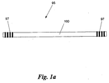
- a fiber laser (95) can be created from an optical fiber (100) that has a laser active medium that emits radiation with a wavelength characteristic of the active medium within the fiber when energy is supplied to the active medium (e.g., by "pump" radiation).
- Two reflectors (97) define a resonant optical cavity in the fiber (100) in which radiation can oscillate and cause the stimulated emission of radiation from the active medium in the fiber.
- the reflectors (97) can be, for example, Bragg gratings written in the fiber (100) or mirrors that can be placed outside the fiber (100). At least one of the reflectors (97) can be partially transmitting, so that radiation is coupled out of the resonant cavity.
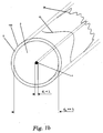
- an optical fiber (100) includes a multimode core region (2) that carries the multi-mode pump light (20), represented by a spiky, multimode intensity distribution, and the fiber laser output light (10), represented by the diffraction-limited, Gaussian intensity distribution.
- the fiber core is embedded in a cladding (3) that ensures effective waveguiding because the cladding has an index of refraction, n 3 , that is less than the index of refraction of the core, n 2 , for both the pump and the laser wavelength.
- n 3 1
- any other desirable low-order mode is possible by discriminating all undesired modes and providing low propagation losses within the fiber (100) only for the desired mode (e.g., a donut mode or TEM 01* mode).
- an active region (1) for generating light at the laser wavelength when pumped with pump light.
- multiple active regions (1) can be distributed within the fiber core (2).
- at least one dimension of the active region (1) is smaller than the size of the lowest-order mode with an output wavelength X.
- the diameter, d 1 , of the active region (1) can be smaller than the wavelength, ⁇ , of the laser output. The small dimension of the active region (1) effectively suppresses the confinement of laser modes inside the active region (1).
- the active region In the more general case, it is not only the size of the region that can confine and guide radiation within the region, but the index contrast of the region with the a surrounding region.
- the active region will support only the lowest order mode when r n 1 2 ⁇ n 2 2 1 / 2 ⁇ 2.405 ⁇ / 2 ⁇ .
- r(n 1 2 - n 2 2 ) 1/2 becomes smaller than this value, a greater proportion of the field leaks out of the active region and into the cladding.
- the active region cannot be said to confine the mode.
- the index of refraction of the active region (1) is index matched to the fiber core region, the active region does not confine the generated radiation by index guiding.
- the diameter, d 2 , of the core region (2) is larger than the wavelength, ⁇ , of the laser output.
- circular symmetry of the fiber core (2) can be broken by separating the fiber core (2) into two semi-circles and displacing one of them with respect to each other.
- a fiber (100) having such a shape, or other similar shapes having a planar window surface (21) substantially parallel to the radial axis of the fiber (100), can be useful for effective side pumping of the fiber (100) through one or more surfaces (21) that are created along the fiber sides.
- pump light enters the fiber (100) through planar surface (21)
- the pump light is totally internally reflected by the curved outer surface (22) of the fiber (100) and is diffused throughout the interior of the fiber (100).
- Fiber core (2) can have a circular cross section, as shown in Fig.
- a fiber core (2) with a broken symmetry can be useful for efficient fiber pumping, because the broken symmetry suppresses the build-up of local modes in the pump light field that is injected into the fiber (100).
- Fiber (100) may be fabricated using standard techniques known in the art.
- a preform may be created using a variety of techniques (e.g., by depositing fused-silica soot on the inside wall of a fused-silica tube and then sintering the resultant tube to form a rod; by depositing fused-silica soot on the on the outside of a ceramic rod, cooling the resulting the structure, extracting the rod, and sintering the resultant tube to form a rod; or by vapor axial deposition of fused-silica soot on a pure silica seed rod to form a rod).
- the preform is cut to the desired cross-sectional shape of the fiber by milling or cutting the preform.
- a cylindrical preform may be cut in half along its longitudinal axis and the two semi-cylindrical halves may be reattached to each other by sintering the two halves together in an offset position from each other to create the cross section desired in the final fiber.
- a fiber is then drawn from the preform using known techniques and the cross-section of the drawn fiber retains the cross-sectional shape of the preform from which it is drawn.
- the active (1) region can be slightly displaced from the center of the fiber core (2), so that it is not broken when the halves of the core (2) are separated.
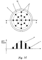
- multiple active regions (1) can be distributed throughout the core (2).
- Each active region (1) has a dimension (e.g., a diameter) and an index contrast with the surrounding core (2) such that radiation generated in the active regions (1) is not confined by the active regions (1).
- the dopant concentration (11) of the individual active regions (1) can differ depending on the location of the individual active region (1) within the core (2). For example, a relatively larger concentration of dopant can be located near the center of the core (2) than at the perimeter of the core (2), such that the total gain over the entire cross section of the core (2) created by the individual active regions (1) stepwise matches the intensity distribution of a desired low-order fiber laser mode (10).
- a fiber (100) includes a cladding (3), a core (2), and multiple active regions (1) that are arranged in the form of thin concentric rings.
- the ring thickness d r and its index contrast with the surrounding material is such that radiation is not confined within the individual active regions (1).
- the dopant concentration of the different rings can be chosen to match the spatial mode profile of a desired mode. For example, to match a Gaussian mode, the axial active region will have a higher dopant concentration than the outermost ring.
- the ring-shaped active regions (1) need not be of circular shape, and they do not have to be concentrically located or located inside each other at all.
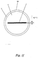
- a fiber (100) includes a cladding (3), a core (2), and a thin slab of active material (1).
- the thickness, d 1 , of the straight or curved slab of active material (1) has a thickness and an index contrast with the surrounding core material (2) such that radiation is not confined within the active material.
- the multitude of active regions (1) distributed within the fiber core can consist of any combination of the basic shapes described above with reference to Figs. 1b - Fig. 1f .
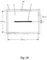
- a fiber (100) includes a cladding (3), active material (1), and a fiber core (2) that can have a rectangular shape, which can be beneficial for diode pumping the fiber laser.
- Both dimensions (height, a, and width, b) of the rectangular fiber core (2) are large enough compared to the fiber laser output wavelength ⁇ to allow for multimode propagation of pump light in the core (2).
- the linear active region is separately shown in Fig. 2b because the linear geometry is especially suited for the rectangular waveguide as shown.
- the height and/or the width of the rectangular fiber core can be about 3- 50 ⁇ m.
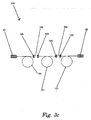
- multiple high-power diode lasers (15) can be used to create the pump radiation that is used to excite the active region(s) within the fiber (100).
- Pump radiation can be injected into the fiber (100) through the sidewall of the fiber.
- pump laser radiation can be coupled through passive, planar glass plates (17) to a planar window (21) etched, cut, or otherwise formed in the fiber (100).
- the pump radiation is coupled through the window (21) and into the core (2) of the fiber (100). While the high power diode lasers are shown to be adjacent to each other, this is not necessary. The distance between any two diode laser can be chosen to best fit the needs of the fiber laser.
- the fiber laser (100) can be side-pumped with one or more multimode diode lasers (60) distributed along the fiber laser that can be wound in overlapping loops, such that a single pump diode laser (60) can inject light into more than one loop of fiber.
- the semi-transparent out-coupling mirror (51) and the reflective rear mirror (52) provide low loss feedback for the desired low order fiber laser mode (10). All pumping techniques can be used to pump the fiber laser (100).
- the fiber laser (100) can be pumped by a multitude of spliced fiber bundles, by shining pump light in to a v-groove in the fiber (100), or by shining pump light through a side facet (21) in the fiber (100).
- the fiber laser (110) can be separated into different sections (101) that are separated by free space propagation paths (102).
- the fiber laser mode leaves the fiber section (101) with a divergence that is characteristic for the mode.
- the laser radiation will propagate in the free space propagation path (102) until it couples to the next fiber section (103'). While low-order modes with low divergence can bridge the free space propagation path (102) without high coupling losses, higher-order modes will suffer substantial coupling losses and will thereby be effectively suppressed. This ensures low-order mode laser operation within the multimode fiber core of the fiber laser (110).
- a fiber laser (110) can be separated into different sections (101) that are separated by distributed mode discriminator sections (130).
- These distributed mode discriminator sections (130) function to allow low order modes with low divergence to pass the distributed mode discriminator sections (130) without high losses, while higher order modes suffer substantial losses and will thereby be effectively suppressed. This ensures low order mode laser operation within the multimode fiber core (2).
- the mode discriminator sections (130) are specified in more detail below.
- Fig. 4a shows a mode discriminating section (130) as two fiber sections (101 and 101') having a fiber core (2) and a fiber cladding (3), which are held in a housing (80) and are separated from each other by a free space propagation path.
- the desirable lowest order mode (21) exists in one of the fiber sections (101) and propagates in free space with a low divergence to the entrance of the other fiber section (101').
- this mode suffers very small losses that do not greatly reduce the efficiency of the laser operation for this mode (21).
- higher order modes (22) suffer substantial losses during the coupling through the free space propagation path because the larger divergence of the higher order mode prohibits efficient coupling to the next fiber section (101').
- the techniques and devices described above are also valid for light propagating in the other direction (from section (101') to section (101)).
- the fiber ends are placed inside the housing (80), their exposed ends within the housing (80) can be sealed from dust using state of the art sealants and sealing techniques (8).
- Fig. 4b shows a mode discriminating section (130) as two fiber sections (101 and 101') having a fiber core (2) and a fiber cladding (3), which are held in a housing (80) and are separated from each other by a free space propagation path.
- an optical element (53) e.g., a lens
- an optical element is located within the free space propagation path between the two fiber sections (101 and 101') to efficiently couple the desired low order mode (21) while also efficiently discriminating unwanted modes (22). Due to the optical element (53), the coupling efficiency for the desired mode (21) is enhanced, because light emerging from the end of one fiber section (101) can be optically imaged to the end of the other fiber section (101').
- the optical element (53) can also be used to discriminate against the lowest order mode, while efficiently coupling a desired higher order mode from one fiber section (101) to another fiber section (101).
- the optical element (53) can consist of one or more lenses that increase the divergence of the lowest order mode to reduce coupling of the lowest order mode from one fiber section (101) to another (101'), while optimizing the coupling efficiency for a desired higher order mode.
- Fig. 4c shows a mode discriminating section (130) as two fiber sections (101 and 101') having a fiber core (2) and a fiber cladding (3), which are held in a housing (80) and are separated from each other by a third fiber section (199), having a core (190) and a fiber cladding (191), that is spliced to the fiber sections (101) and (101') at positions (200).
- the cross section of the core (190) is larger than the cross section of core (2) of fiber sections (101) and (101').
- the desirable lowest order mode (21) passes through fiber section (199) with a low divergence and therefore with low loss.
- higher order modes (22) suffer substantial losses during passing fiber section (199) because they diverge quickly in core 190.
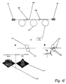
- Fig. 4d shows a mode discriminating section (130) similar to the one described in Fig. 4c , but the index of refraction (201) of the core (190) of the discriminating fiber section (199) varies radially.
- the index of refraction can vary, for example, smoothly from a higher value on the axis of the core 190 to a smaller value at a distance from the center of the core, as is shown by the graph in Fig. 4d .
- This index of refraction profile will act as a conduit for low order modes and therefore decrease their losses during the pass of fiber section (199), while increasing the losses of higher order modes by increasing the divergence of the higher order modes.
- the cladding (191) can have a smaller value of index of refraction than the core (190).
- Fig. 4e shows a mode discriminating section (130) similar to the one described in Fig. 4c , but the discriminating fiber section (199) can include a fiber grating (192) that increases the losses of undesired modes (22) (e.g., high divergence modes), while allowing a desired mode (e.g., a low divergence mode) to pass with low loss.
- the grating (192) can act like a conduit for low order modes and therefore even decrease their losses during the pass of fiber section (199), while it increases the losses of the higher order modes by increasing their divergence.
- distributed mode discriminator sections (130) consist of the fiber (100) itself without sectioning or splicing of the fiber.
- the mode discrimination is achieved by using tightly bent fiber sections (130) (with bending radii on the order of a few to a few tens of centimeters)
- the bent fiber sections (130) can be bent in a circular or in a kidney shape.
- a multimode laser beam (210) passes through such a tightly bent section (130) of the fiber (100) having a multimode fiber core with a diameter, d » ⁇ (e.g., a diameter of 30 ⁇ m or greater)
- a monomode laser beam (211) emerges from the tightly bent section of the fiber.
- the tightly bent fiber sections (131) can be combined in three-dimensional arrangements, as shown in Fig. 4f , to homogenously discriminate modes that are traveling in the fiber (100). For example, bending a fiber (100) in a clockwise direction (131) can suppress a mode that travels at the outer fiber radius, while not suppressing a mode at the inner fiber radius. By adding a counterclockwise bent fiber (131') section, the mode that traveled at the inner radius in the clockwise bent fiber section (131) now travels at the outer radius of the counterclockwise bent fiber section (131') and is discriminated. This principle can be expanded to more than two dimensions, as shown in Fig. 4f .
- the laser light emerging from the end of a fiber section (101) can be retroreflected by an out-coupler (51) or rear mirror (52) of the laser resonator.
- the lowest order mode (21) can emerge from the fiber end and propagate through free space at a low divergence and be reflected by the out-coupler mirror (51) or rear mirror (52) and travel back through free space to the fiber end and couple efficiently back into the fiber end.
- Higher order modes (22) are effectively suppressed because their higher divergence prohibits efficient reentry (coupling) to the fiber end after being retroreflected by the outcoupler (51) or rear mirror (52).
- a curved surface curvature (54) of outcoupler (51) or rear mirror (52) can optimize the coupling of the desired mode (21) to the fiber end. Utilizing this technique, the coupling of the desired mode to the fiber end after free space propagation and mirror reflection can be further enhanced, while the coupling efficiency of any undesired mode can be further decreased.
- the lowest order mode can be reflected by an optimized fiber grating (55).
- This fiber grating is optimized for the reflection of the desired mode (21), which in this case does not leave the fiber end, while at least partially transmitting all higher order modes (22).
- the higher order modes experience increased outcoupling losses and therefore are efficiently suppressed.
Landscapes
- Physics & Mathematics (AREA)
- Electromagnetism (AREA)
- Engineering & Computer Science (AREA)
- Plasma & Fusion (AREA)
- Optics & Photonics (AREA)
- Lasers (AREA)
- Optical Couplings Of Light Guides (AREA)
- Manufacture, Treatment Of Glass Fibers (AREA)
Claims (18)
- Fibre optique (100) pour produire un rayonnement laser à une longueur d'onde caractéristique, la fibre optique (100) comprenant :une première région de coeur multimode (2) ayant un premier indice de réfraction, la région de coeur (2) étant conçue pour guider un rayonnement de pompage (20) ; etune région active (1) incorporée dans la région de coeur (2) pour produire un rayonnement à la longueur d'onde caractéristique lorsqu'elle est pompée par le rayonnement de pompage (20),caractérisée en ce que la région de coeur (2) est conçue pour guider le rayonnement laser dans une direction longitudinale de la fibre (100) et que la région active (1) a une dimension transversale plus petite que la longueur d'onde caractéristique, de sorte que le rayonnement produit dans la région active (1) ne soit pas confiné dans la région active (1).
- Fibre optique selon la revendication 1, dans laquelle moins d'environ 50 %, de préférence moins d'environ 10 %, plus préférentiellement moins d'environ 5 %, le plus préférentiellement moins d'environ 2 % du rayonnement produit à la longueur d'onde caractéristique dans la région active (1) sont confinés dans la région active (1).
- Fibre optique selon la revendication 1, dans laquelle la région active (1) a un deuxième indice de réfraction différent du premier indice de réfraction, et la combinaison de la dimension transversale de la région active (1) et de la différence entre le premier indice de réfraction et le deuxième indice de réfraction est telle que le rayonnement produit dans la région active (1) n'est pas confiné dans la région active.
- Fibre optique selon la revendication 1, dans laquelle le mode désiré est le mode d'ordre le plus bas de la fibre optique (100), de préférence un mode gaussien de la fibre optique (100).
- Fibre optique selon la revendication 1, dans laquelle la fibre optique (100) a un gain suivant sa direction longitudinale qui est suffisamment petit pour qu'un mode de laser désiré fonctionne au-dessus d'un seuil d'effet laser tandis que tous les autres modes fonctionnent au-dessous du seuil d'effet laser.
- Fibre optique selon la revendication 1, comprenant en outre un discriminateur de modes (130) pour discriminer les modes de lumière non désirés générés dans la fibre multimode (100) tout en permettant à un mode de lumière désiré de se propager dans la fibre multimode (100).
- Fibre optique selon la revendication 6, dans laquelle le discriminateur de modes (130) est un trajet de propagation en espace libre défini entre un miroir et la première fibre multimode (100) ou un réseau de fibre.
- Fibre optique selon la revendication 7, comprenant en outre un élément optique, de préférence un miroir, situé dans le trajet de propagation en espace libre, et
dans laquelle l'élément optique est conçu pour transmettre la lumière émise par la première fibre multimode (100) dans un mode désiré et rétroréfléchie par le miroir en retour dans la fibre multimode (100) et est conçu pour ne pas transmettre la lumière émise par la première fibre multimode (100) dans des modes non désirés en retour dans la première fibre multimode (100). - Fibre optique selon la revendication 6, comprenant en outre :une deuxième fibre optique multimode (101') pour guider le rayonnement laser, etdans laquelle le discriminateur de modes (130) est un trajet de propagation en espace libre entre la première fibre multimode (101) et la deuxième fibre multimode (101').
- Fibre optique selon la revendication 9, comprenant en outre :un élément optique (53), de préférence une lentille, situé dans le trajet de propagation en espace libre, etdans laquelle l'élément optique (53) est conçu pour transmettre la lumière émise par la première fibre multimode (101) dans un mode désiré dans la deuxième fibre optique multimode (101').
- Fibre optique selon la revendication 6, comprenant en outre :une deuxième fibre optique multimode (101') pour guider le rayonnement laser, etdans laquelle le discriminateur de modes (130) est une troisième fibre multimode (199) située entre la première fibre multimode (101) et la deuxième fibre multimode (101') et ayant de préférence un indice de réfraction qui varie dans la direction radiale de la fibre.
- Fibre optique selon la revendication 6, dans laquelle the discriminateur de modes (130) est une section étroitement repliée (131) de la fibre optique (100), de préférence repliée sensiblement en forme de rein.
- Fibre optique selon la revendication 6, dans laquelle le discriminateur de modes (130) est constitué de plusieurs sections étroitement repliées (131, 131') de la fibre optique (100), les sections repliées (131, 131') étant situées sensiblement dans des plans non parallèles, et de préférence au moins une section de fibre étroitement repliée étant repliée sensiblement en forme de rein.
- Fibre optique selon la revendication 1, comprenant en outre un moyen discriminateur de modes (130) pour discriminer des modes non désirés de lumière générés dans la fibre multimode (100) tout en permettant à un mode désiré de lumière de se propager dans la fibre multimode (100).
- Fibre optique selon la revendication 14, dans laquelle la dimension transversale de la région active (1) est plus petite que la longueur d'onde caractéristique.
- Fibre optique selon la revendication 14, dans laquelle le mode désiré est le mode d'ordre de plus bas, de préférence un mode gaussien.
- Fibre optique selon la revendication 14, dans laquelle la fibre optique (100) a un gain suivant sa direction longitudinale qui est suffisamment petit pour qu'un mode de laser désiré fonctionne au-dessus d'un seuil d'effet laser tandis que tous les autres modes fonctionnent au-dessous du seuil d'effet laser.
- Procédé pour fournir une énergie laser d'une longueur d'onde caractéristique dans un seul mode optique à une surface, le procédé consistant à :pomper une région active (1) incorporée dans une fibre optique multimode (100) avec une énergie de pompage pour produire l'énergie laser à la longueur d'onde caractéristique, la région active (1) ayant une dimension transversale plus petite que la longueur d'onde caractéristique ; etguider la lumière générée vers la surface avec la fibre multimode (100).
Applications Claiming Priority (5)
| Application Number | Priority Date | Filing Date | Title |
|---|---|---|---|
| US44212303P | 2003-01-24 | 2003-01-24 | |
| US442123P | 2003-01-24 | ||
| US47044603P | 2003-05-15 | 2003-05-15 | |
| US470446P | 2003-05-15 | ||
| PCT/EP2004/000610 WO2004066458A2 (fr) | 2003-01-24 | 2004-01-26 | Laser a fibre |
Publications (2)
| Publication Number | Publication Date |
|---|---|
| EP1586144A2 EP1586144A2 (fr) | 2005-10-19 |
| EP1586144B1 true EP1586144B1 (fr) | 2016-05-11 |
Family
ID=32776118
Family Applications (1)
| Application Number | Title | Priority Date | Filing Date |
|---|---|---|---|
| EP04705059.6A Expired - Lifetime EP1586144B1 (fr) | 2003-01-24 | 2004-01-26 | Laser a fibre |
Country Status (4)
| Country | Link |
|---|---|
| US (1) | US7542488B2 (fr) |
| EP (1) | EP1586144B1 (fr) |
| JP (1) | JP4714136B2 (fr) |
| WO (1) | WO2004066458A2 (fr) |
Families Citing this family (18)
| Publication number | Priority date | Publication date | Assignee | Title |
|---|---|---|---|---|
| DE102004062849A1 (de) * | 2004-12-27 | 2006-07-06 | Carl Baasel Lasertechnik Gmbh & Co. Kg | Laseraktive optische Faser für einen Faserlaser oder einen faseroptischen Verstärker |
| FR2903817B1 (fr) * | 2006-07-13 | 2010-06-25 | Femlight | Dispositif laser a fibre optique de puissance |
| US8412015B2 (en) | 2007-02-05 | 2013-04-02 | Ofs Fitel, Llc | Segmented gain-doping of an optical fiber |
| JP5370714B2 (ja) * | 2007-05-31 | 2013-12-18 | ソニー株式会社 | 光導波路、および信号処理装置 |
| US7983312B2 (en) | 2007-08-09 | 2011-07-19 | Raytheon Company | Method and apparatus for generation and amplification of light in a semi-guiding high aspect ratio core fiber |
| JP5391077B2 (ja) * | 2007-11-19 | 2014-01-15 | ミヤチテクノス株式会社 | レーザ光照射装置 |
| US7746914B2 (en) * | 2008-01-16 | 2010-06-29 | Jds Uniphase Corporation | Waveguide retroreflector and method of fabricating the same |
| US8620121B2 (en) * | 2008-03-12 | 2013-12-31 | Jds Uniphase Corporation | Tapered fiber retroreflector |
| JP5178328B2 (ja) * | 2008-06-05 | 2013-04-10 | 三菱電線工業株式会社 | 光ファイバ |
| WO2010056253A1 (fr) * | 2008-11-17 | 2010-05-20 | Raytheon Company | Procédé et appareil de génération et d'amplification de lumière dans une fibre à coeur à rapport de forme élevé à semi-guidage |
| JP5299959B2 (ja) * | 2008-12-02 | 2013-09-25 | 国立大学法人東北大学 | 光ビーム増幅方法および光ビーム増幅装置 |
| US8498044B2 (en) * | 2009-12-22 | 2013-07-30 | Fujikura Ltd. | Amplification optical fiber, and optical fiber amplifier and resonator using the same |
| JP4667535B1 (ja) * | 2010-11-02 | 2011-04-13 | 株式会社フジクラ | 増幅用光ファイバ、及び、それを用いた光ファイバ増幅器及び共振器 |
| EP2696451B1 (fr) * | 2011-03-31 | 2017-10-11 | Fujikura Co., Ltd. | Fibre optique d'amplification, et amplificateur à fibres optiques et résonateur l'utilisant |
| CN113069204A (zh) * | 2014-11-14 | 2021-07-06 | 波士顿科学医学有限公司 | 手术激光系统和激光装置 |
| JP6796142B2 (ja) * | 2016-04-06 | 2020-12-02 | テラダイオード, インコーポレーテッド | 可変レーザビームプロファイルのための光ファイバ構造および方法 |
| JP6663387B2 (ja) | 2017-05-08 | 2020-03-11 | 株式会社フジクラ | マルチモードファイバ、光増幅器、及びファイバレーザ |
| US11502477B2 (en) * | 2020-02-26 | 2022-11-15 | Lumentum Operations Llc | In-fiber retroreflector |
Family Cites Families (68)
| Publication number | Priority date | Publication date | Assignee | Title |
|---|---|---|---|---|
| US54740A (en) * | 1866-05-15 | Improved handle for coffee, spice, and other small mills | ||
| US4829529A (en) | 1987-06-15 | 1989-05-09 | Spectra-Physics, Inc. | Laser diode pumped fiber lasers with pump cavity |
| US4815079A (en) | 1987-12-17 | 1989-03-21 | Polaroid Corporation | Optical fiber lasers and amplifiers |
| US5027079A (en) * | 1990-01-19 | 1991-06-25 | At&T Bell Laboratories | Erbium-doped fiber amplifier |
| FR2659755B1 (fr) * | 1990-03-16 | 1992-05-29 | Alcatel Nv | Amplificateur optique a fibre dopee a l'erbium. |
| US5212707A (en) | 1991-12-06 | 1993-05-18 | Mcdonnell Douglas Corporation | Array of diffraction limited lasers and method of aligning same |
| JPH09505881A (ja) * | 1993-09-14 | 1997-06-10 | バード ファイバーオプティック テクノロジーズ,インコーポレイテッド | 所定位置較正のためのドリフト補正手段を有する光ファイバ圧力センサ |
| EP0723715B1 (fr) | 1993-10-13 | 1998-08-26 | ITALTEL SOCIETA ITALIANA TELECOMUNICAZIONI s.p.a. | Laser monomode a fibres optiques pompe par diode a emission continue sur 976 nm |
| EP0723714A1 (fr) | 1993-10-13 | 1996-07-31 | ITALTEL SOCIETA ITALIANA TELECOMUNICAZIONI s.p.a. | Amplificateur de fibre optique a haut gain a pompage par laser multi-mode |
| US5422897A (en) * | 1994-01-28 | 1995-06-06 | British Telecommunications Public Limited Company | Two-stage mono-mode optical fibre laser |
| US5418880A (en) | 1994-07-29 | 1995-05-23 | Polaroid Corporation | High-power optical fiber amplifier or laser device |
| US5566196A (en) * | 1994-10-27 | 1996-10-15 | Sdl, Inc. | Multiple core fiber laser and optical amplifier |
| ES2126879T3 (es) * | 1994-12-28 | 1999-04-01 | Italtel Spa | Disposicion de acoplamiento entre una fuente luminosa de multiples modos y una fibra optica a traves de un tramo de fibra optica intermedio. |
| US5694408A (en) * | 1995-06-07 | 1997-12-02 | Mcdonnell Douglas Corporation | Fiber optic laser system and associated lasing method |
| US5710786A (en) * | 1995-08-25 | 1998-01-20 | Sdl, Inc. | Optical fibre laser pump source for fibre amplifiers |
| US5627848A (en) * | 1995-09-05 | 1997-05-06 | Imra America, Inc. | Apparatus for producing femtosecond and picosecond pulses from modelocked fiber lasers cladding pumped with broad area diode laser arrays |
| DE19535526C1 (de) | 1995-09-25 | 1997-04-03 | Hannover Laser Zentrum | Doppelkern-Faserlaser |
| US5867305A (en) * | 1996-01-19 | 1999-02-02 | Sdl, Inc. | Optical amplifier with high energy levels systems providing high peak powers |
| GB2309820A (en) | 1996-02-01 | 1997-08-06 | Imperial College | Q-switched fibre laser |
| US5790722A (en) | 1996-04-16 | 1998-08-04 | Hughes Electronics | High power optical fiber amplifier/laser system |
| WO1997039503A1 (fr) | 1996-04-16 | 1997-10-23 | Massachusetts Institute Of Technology | Faisceau de fibres optiques a fibre optique monomode entouree de fibres optiques multimode et procede de fabrication |
| DE19620159C2 (de) | 1996-05-07 | 2002-08-08 | Inst Physikalische Hochtech Ev | Faserlaser oder Faserverstärker mit neuartiger Brechzahlstruktur |
| JP3833313B2 (ja) * | 1996-08-30 | 2006-10-11 | 株式会社日立製作所 | 半導体レーザ素子 |
| JP3920384B2 (ja) | 1996-10-31 | 2007-05-30 | 憲一 植田 | 光ファイバレーザ装置 |
| US5805621A (en) * | 1996-11-12 | 1998-09-08 | Lucent Technologies, Inc. | Fiber multimode laser with reduced noise |
| GB9625231D0 (en) * | 1996-12-04 | 1997-01-22 | Univ Southampton | Optical amplifiers & lasers |
| GB2366447B (en) | 1996-12-04 | 2002-04-17 | Southampton Photonics Ltd | Apparatus for Amplifying a Signal Beam having a Normalised Intensity Distribution |
| US5880877A (en) * | 1997-01-28 | 1999-03-09 | Imra America, Inc. | Apparatus and method for the generation of high-power femtosecond pulses from a fiber amplifier |
| US6151338A (en) * | 1997-02-19 | 2000-11-21 | Sdl, Inc. | High power laser optical amplifier system |
| US5905745A (en) * | 1997-03-17 | 1999-05-18 | Sdl, Inc. | Noise suppression in cladding pumped fiber lasers |
| US5790720A (en) * | 1997-05-06 | 1998-08-04 | Lucent Technologies, Inc. | Acoustic-optic silica optical circuit switch |
| EP0984844B1 (fr) * | 1997-05-27 | 2002-11-13 | SDL, Inc. | Systeme de marquage au laser et procede de commande d'energie |
| US5818630A (en) * | 1997-06-25 | 1998-10-06 | Imra America, Inc. | Single-mode amplifiers and compressors based on multi-mode fibers |
| US6181466B1 (en) * | 1997-08-23 | 2001-01-30 | Pirelle Cavi E Sistemi S.P.A. | Unequal couplers for multimode pumping optical amplifiers |
| US6031849A (en) * | 1997-11-14 | 2000-02-29 | Jds Uniphase Corporation | High power three level fiber laser and method of making same |
| US6049415A (en) * | 1997-12-08 | 2000-04-11 | Sdl, Inc. | Polarization maintaining fiber lasers and amplifiers |
| DE19905491A1 (de) | 1998-02-12 | 1999-08-19 | Rofin Sinar Laser Gmbh | Laserfaser und Verfahren zu ihrer Herstellung |
| WO1999045419A1 (fr) | 1998-03-04 | 1999-09-10 | Sdl, Inc. | Coupleurs optiques pour fibres multimodes |
| US6275250B1 (en) * | 1998-05-26 | 2001-08-14 | Sdl, Inc. | Fiber gain medium marking system pumped or seeded by a modulated laser diode source and method of energy control |
| GB9814526D0 (en) * | 1998-07-03 | 1998-09-02 | Univ Southampton | Optical fibre and optical fibre device |
| DE19829684B4 (de) | 1998-07-03 | 2005-07-07 | Jenoptik Ldt Gmbh | Modulierbarer Faserlaser |
| US6144677A (en) | 1998-08-11 | 2000-11-07 | Trw Inc. | High average power fiber laser system with phase conjugation |
| US6275512B1 (en) * | 1998-11-25 | 2001-08-14 | Imra America, Inc. | Mode-locked multimode fiber laser pulse source |
| US6101199A (en) * | 1999-01-05 | 2000-08-08 | Apollo Instruments, Inc. | High power high efficiency cladding pumping fiber laser |
| FR2789813B1 (fr) * | 1999-02-15 | 2001-10-05 | Cit Alcatel | Amplificateur optique |
| US6240108B1 (en) * | 1999-02-17 | 2001-05-29 | Hughes Electronics Corporation | Cladding pumped fiber laser with reduced overlap between a laser mode and an ion-doped region |
| US6301421B1 (en) * | 1999-05-27 | 2001-10-09 | Trw Inc. | Photonic crystal fiber lasers and amplifiers for high power |
| DE19925686A1 (de) | 1999-06-04 | 2000-12-14 | Zeiss Carl Jena Gmbh | Laser mit einem Lichtleitfaser |
| US6324326B1 (en) * | 1999-08-20 | 2001-11-27 | Corning Incorporated | Tapered fiber laser |
| WO2001024326A1 (fr) | 1999-09-29 | 2001-04-05 | Optical Technologies Italia S.P.A. | Procede de fabrication de laser a fibre |
| DE19964083C2 (de) | 1999-12-27 | 2002-02-07 | Forschungsverbund Berlin Ev | Laserverstärkersystem mit zeitproportionaler Frequenzmodulation |
| US6330382B1 (en) * | 2000-01-19 | 2001-12-11 | Corning Incorporated | Mode conditioning for multimode fiber systems |
| DE10006050B4 (de) | 2000-02-10 | 2007-10-18 | Jenoptik Ldt Gmbh | Direkt modulierbarer Laser |
| DE10009380B4 (de) | 2000-02-29 | 2007-11-08 | Jenoptik Ldt Gmbh | Faserverstärker |
| DE10009381B4 (de) | 2000-02-29 | 2005-02-24 | Jenoptik Ldt Gmbh | Anordnung zur Erzeugung roter, grüner und blauer Laserstrahlung |
| DE10009379C2 (de) | 2000-02-29 | 2002-04-25 | Schneider Laser Technologies | Faseroptischer Verstärker |
| WO2002011255A1 (fr) | 2000-07-31 | 2002-02-07 | Kigre, Inc. | Structure laser a fibre optique et systeme base sur le pompage d'emission spontanee amplifiee d'elements d'enveloppe |
| US6467969B1 (en) | 2000-09-15 | 2002-10-22 | Agere Systems Guardian Corp. | Article comprising a multimode optical fiber coupler |
| US6445838B1 (en) * | 2000-09-29 | 2002-09-03 | Corning Incorporated | Tunable optical component |
| GB0025185D0 (en) | 2000-10-13 | 2000-11-29 | Southampton Photonics Ltd | Opitcal multi-band device |
| US6483974B1 (en) * | 2000-10-24 | 2002-11-19 | Jds Uniphase Corporation | Optical fiber with improved cross-sectional profile and optical gain media using same |
| US6608951B1 (en) | 2000-11-28 | 2003-08-19 | Lew Goldberg | Optical fiber amplifiers and lasers and optical pumping device therefor |
| DE10059314B4 (de) | 2000-11-29 | 2018-08-02 | Tesat-Spacecom Gmbh & Co.Kg | Lichtleitende Faser und Verfahren zum Herstellen einer lichtleitenden Faser |
| US6954575B2 (en) | 2001-03-16 | 2005-10-11 | Imra America, Inc. | Single-polarization high power fiber lasers and amplifiers |
| DE60230509D1 (de) | 2001-03-30 | 2009-02-05 | Ocg Technology Licensing Llc | Ringkernfaser |
| JP4947853B2 (ja) * | 2001-06-25 | 2012-06-06 | 三菱電線工業株式会社 | 希土類元素ドープファイバ |
| US6823117B2 (en) | 2001-12-07 | 2004-11-23 | Coherent, Inc. | Mode multiplexing optical coupling device |
| US6970631B2 (en) * | 2002-06-05 | 2005-11-29 | Lightwave Electronics | Suppression of cladding mode loss in fiber amplifiers with distributed suppression of amplified spontaneous emission (ASE) |
-
2004
- 2004-01-26 EP EP04705059.6A patent/EP1586144B1/fr not_active Expired - Lifetime
- 2004-01-26 US US10/763,390 patent/US7542488B2/en active Active
- 2004-01-26 WO PCT/EP2004/000610 patent/WO2004066458A2/fr active Application Filing
- 2004-01-26 JP JP2006500012A patent/JP4714136B2/ja not_active Expired - Fee Related
Also Published As
| Publication number | Publication date |
|---|---|
| JP4714136B2 (ja) | 2011-06-29 |
| US20040218635A1 (en) | 2004-11-04 |
| WO2004066458A2 (fr) | 2004-08-05 |
| JP2006516811A (ja) | 2006-07-06 |
| EP1586144A2 (fr) | 2005-10-19 |
| WO2004066458A3 (fr) | 2004-11-04 |
| US7542488B2 (en) | 2009-06-02 |
Similar Documents
| Publication | Publication Date | Title |
|---|---|---|
| EP1586144B1 (fr) | Laser a fibre | |
| JP5238509B2 (ja) | フォトニックバンドギャップファイバ | |
| US6801550B1 (en) | Multiple emitter side pumping method and apparatus for fiber lasers | |
| US8565272B2 (en) | Method and apparatus for generation and amplification of light in a semi-guiding high aspect ratio core fiber | |
| US6987783B2 (en) | Three-level air-clad rare-earth doped fiber laser/amplifier | |
| EP2503653B1 (fr) | Fibre optique d'amplification, amplificateur à fibre optique et résonateur l'utilisant | |
| US6831934B2 (en) | Cladding pumped fiber laser | |
| JP4443627B2 (ja) | 光ファイバレーザ | |
| EP2100349B1 (fr) | Laser à fibre optique pompé par la gaine avec un degré élevé d'isolation de la source de pompage | |
| US6904219B1 (en) | Ultra high-power continuous wave planar waveguide amplifiers and lasers | |
| EP1731936B1 (fr) | Amplificateur a fibre optique et procede d'amplification optique utilisant ledit amplificateur | |
| JP2010129886A (ja) | ファイバレーザ用光ファイバ及びファイバレーザ | |
| US20090262416A1 (en) | Cascade laser | |
| US10944234B2 (en) | Optical fiber for light amplification having a core with low bend loss and end features with high bend loss and related method | |
| US11835776B2 (en) | Filter device and laser apparatus | |
| EP1586145B1 (fr) | Laser a fibre a pompage lateral | |
| AU2009200094A1 (en) | Cascade laser | |
| EP2677609B1 (fr) | Procédé et appareil de génération et d'amplification de lumière dans une fibre à semi-guidage à coeur à rapport de forme élevé | |
| Seo et al. | Single Mode Laser Oscillation in an Nd‐Doped Large Core Double Clad Fiber Cavity with Concatenated Adiabatic Tapers | |
| CN113228430A (zh) | 用于减少信号组合系统中的受激拉曼散射(srs)光强度的光纤装置和方法 |
Legal Events
| Date | Code | Title | Description |
|---|---|---|---|
| PUAI | Public reference made under article 153(3) epc to a published international application that has entered the european phase |
Free format text: ORIGINAL CODE: 0009012 |
|
| 17P | Request for examination filed |
Effective date: 20050721 |
|
| AK | Designated contracting states |
Kind code of ref document: A2 Designated state(s): AT BE BG CH CY CZ DE DK EE ES FI FR GB GR HU IE IT LI LU MC NL PT RO SE SI SK TR |
|
| AX | Request for extension of the european patent |
Extension state: AL LT LV MK |
|
| DAX | Request for extension of the european patent (deleted) | ||
| 17Q | First examination report despatched |
Effective date: 20130109 |
|
| GRAP | Despatch of communication of intention to grant a patent |
Free format text: ORIGINAL CODE: EPIDOSNIGR1 |
|
| INTG | Intention to grant announced |
Effective date: 20151204 |
|
| GRAS | Grant fee paid |
Free format text: ORIGINAL CODE: EPIDOSNIGR3 |
|
| GRAL | Information related to payment of fee for publishing/printing deleted |
Free format text: ORIGINAL CODE: EPIDOSDIGR3 |
|
| GRAS | Grant fee paid |
Free format text: ORIGINAL CODE: EPIDOSNIGR3 |
|
| GRAA | (expected) grant |
Free format text: ORIGINAL CODE: 0009210 |
|
| AK | Designated contracting states |
Kind code of ref document: B1 Designated state(s): AT BE BG CH CY CZ DE DK EE ES FI FR GB GR HU IE IT LI LU MC NL PT RO SE SI SK TR |
|
| REG | Reference to a national code |
Ref country code: GB Ref legal event code: FG4D |
|
| REG | Reference to a national code |
Ref country code: CH Ref legal event code: EP |
|
| REG | Reference to a national code |
Ref country code: AT Ref legal event code: REF Ref document number: 799326 Country of ref document: AT Kind code of ref document: T Effective date: 20160515 |
|
| REG | Reference to a national code |
Ref country code: IE Ref legal event code: FG4D |
|
| REG | Reference to a national code |
Ref country code: DE Ref legal event code: R096 Ref document number: 602004049277 Country of ref document: DE |
|
| REG | Reference to a national code |
Ref country code: NL Ref legal event code: MP Effective date: 20160511 |
|
| PG25 | Lapsed in a contracting state [announced via postgrant information from national office to epo] |
Ref country code: NL Free format text: LAPSE BECAUSE OF FAILURE TO SUBMIT A TRANSLATION OF THE DESCRIPTION OR TO PAY THE FEE WITHIN THE PRESCRIBED TIME-LIMIT Effective date: 20160511 Ref country code: FI Free format text: LAPSE BECAUSE OF FAILURE TO SUBMIT A TRANSLATION OF THE DESCRIPTION OR TO PAY THE FEE WITHIN THE PRESCRIBED TIME-LIMIT Effective date: 20160511 |
|
| REG | Reference to a national code |
Ref country code: AT Ref legal event code: MK05 Ref document number: 799326 Country of ref document: AT Kind code of ref document: T Effective date: 20160511 |
|
| PG25 | Lapsed in a contracting state [announced via postgrant information from national office to epo] |
Ref country code: PT Free format text: LAPSE BECAUSE OF FAILURE TO SUBMIT A TRANSLATION OF THE DESCRIPTION OR TO PAY THE FEE WITHIN THE PRESCRIBED TIME-LIMIT Effective date: 20160912 Ref country code: SE Free format text: LAPSE BECAUSE OF FAILURE TO SUBMIT A TRANSLATION OF THE DESCRIPTION OR TO PAY THE FEE WITHIN THE PRESCRIBED TIME-LIMIT Effective date: 20160511 Ref country code: ES Free format text: LAPSE BECAUSE OF FAILURE TO SUBMIT A TRANSLATION OF THE DESCRIPTION OR TO PAY THE FEE WITHIN THE PRESCRIBED TIME-LIMIT Effective date: 20160511 Ref country code: GR Free format text: LAPSE BECAUSE OF FAILURE TO SUBMIT A TRANSLATION OF THE DESCRIPTION OR TO PAY THE FEE WITHIN THE PRESCRIBED TIME-LIMIT Effective date: 20160812 |
|
| PG25 | Lapsed in a contracting state [announced via postgrant information from national office to epo] |
Ref country code: IT Free format text: LAPSE BECAUSE OF FAILURE TO SUBMIT A TRANSLATION OF THE DESCRIPTION OR TO PAY THE FEE WITHIN THE PRESCRIBED TIME-LIMIT Effective date: 20160511 |
|
| REG | Reference to a national code |
Ref country code: FR Ref legal event code: PLFP Year of fee payment: 14 |
|
| PG25 | Lapsed in a contracting state [announced via postgrant information from national office to epo] |
Ref country code: SK Free format text: LAPSE BECAUSE OF FAILURE TO SUBMIT A TRANSLATION OF THE DESCRIPTION OR TO PAY THE FEE WITHIN THE PRESCRIBED TIME-LIMIT Effective date: 20160511 Ref country code: DK Free format text: LAPSE BECAUSE OF FAILURE TO SUBMIT A TRANSLATION OF THE DESCRIPTION OR TO PAY THE FEE WITHIN THE PRESCRIBED TIME-LIMIT Effective date: 20160511 Ref country code: RO Free format text: LAPSE BECAUSE OF FAILURE TO SUBMIT A TRANSLATION OF THE DESCRIPTION OR TO PAY THE FEE WITHIN THE PRESCRIBED TIME-LIMIT Effective date: 20160511 Ref country code: EE Free format text: LAPSE BECAUSE OF FAILURE TO SUBMIT A TRANSLATION OF THE DESCRIPTION OR TO PAY THE FEE WITHIN THE PRESCRIBED TIME-LIMIT Effective date: 20160511 Ref country code: CZ Free format text: LAPSE BECAUSE OF FAILURE TO SUBMIT A TRANSLATION OF THE DESCRIPTION OR TO PAY THE FEE WITHIN THE PRESCRIBED TIME-LIMIT Effective date: 20160511 |
|
| REG | Reference to a national code |
Ref country code: DE Ref legal event code: R097 Ref document number: 602004049277 Country of ref document: DE |
|
| PG25 | Lapsed in a contracting state [announced via postgrant information from national office to epo] |
Ref country code: AT Free format text: LAPSE BECAUSE OF FAILURE TO SUBMIT A TRANSLATION OF THE DESCRIPTION OR TO PAY THE FEE WITHIN THE PRESCRIBED TIME-LIMIT Effective date: 20160511 Ref country code: BE Free format text: LAPSE BECAUSE OF FAILURE TO SUBMIT A TRANSLATION OF THE DESCRIPTION OR TO PAY THE FEE WITHIN THE PRESCRIBED TIME-LIMIT Effective date: 20160511 |
|
| PLBE | No opposition filed within time limit |
Free format text: ORIGINAL CODE: 0009261 |
|
| STAA | Information on the status of an ep patent application or granted ep patent |
Free format text: STATUS: NO OPPOSITION FILED WITHIN TIME LIMIT |
|
| 26N | No opposition filed |
Effective date: 20170214 |
|
| PG25 | Lapsed in a contracting state [announced via postgrant information from national office to epo] |
Ref country code: SI Free format text: LAPSE BECAUSE OF FAILURE TO SUBMIT A TRANSLATION OF THE DESCRIPTION OR TO PAY THE FEE WITHIN THE PRESCRIBED TIME-LIMIT Effective date: 20160511 |
|
| REG | Reference to a national code |
Ref country code: CH Ref legal event code: PL |
|
| PG25 | Lapsed in a contracting state [announced via postgrant information from national office to epo] |
Ref country code: MC Free format text: LAPSE BECAUSE OF FAILURE TO SUBMIT A TRANSLATION OF THE DESCRIPTION OR TO PAY THE FEE WITHIN THE PRESCRIBED TIME-LIMIT Effective date: 20160511 |
|
| PG25 | Lapsed in a contracting state [announced via postgrant information from national office to epo] |
Ref country code: CH Free format text: LAPSE BECAUSE OF NON-PAYMENT OF DUE FEES Effective date: 20170131 Ref country code: LI Free format text: LAPSE BECAUSE OF NON-PAYMENT OF DUE FEES Effective date: 20170131 |
|
| REG | Reference to a national code |
Ref country code: IE Ref legal event code: MM4A |
|
| PG25 | Lapsed in a contracting state [announced via postgrant information from national office to epo] |
Ref country code: LU Free format text: LAPSE BECAUSE OF NON-PAYMENT OF DUE FEES Effective date: 20170126 |
|
| REG | Reference to a national code |
Ref country code: FR Ref legal event code: PLFP Year of fee payment: 15 |
|
| PG25 | Lapsed in a contracting state [announced via postgrant information from national office to epo] |
Ref country code: IE Free format text: LAPSE BECAUSE OF NON-PAYMENT OF DUE FEES Effective date: 20170126 |
|
| PG25 | Lapsed in a contracting state [announced via postgrant information from national office to epo] |
Ref country code: HU Free format text: LAPSE BECAUSE OF FAILURE TO SUBMIT A TRANSLATION OF THE DESCRIPTION OR TO PAY THE FEE WITHIN THE PRESCRIBED TIME-LIMIT; INVALID AB INITIO Effective date: 20040126 |
|
| PG25 | Lapsed in a contracting state [announced via postgrant information from national office to epo] |
Ref country code: BG Free format text: LAPSE BECAUSE OF FAILURE TO SUBMIT A TRANSLATION OF THE DESCRIPTION OR TO PAY THE FEE WITHIN THE PRESCRIBED TIME-LIMIT Effective date: 20160511 |
|
| PG25 | Lapsed in a contracting state [announced via postgrant information from national office to epo] |
Ref country code: CY Free format text: LAPSE BECAUSE OF NON-PAYMENT OF DUE FEES Effective date: 20160511 |
|
| PG25 | Lapsed in a contracting state [announced via postgrant information from national office to epo] |
Ref country code: TR Free format text: LAPSE BECAUSE OF FAILURE TO SUBMIT A TRANSLATION OF THE DESCRIPTION OR TO PAY THE FEE WITHIN THE PRESCRIBED TIME-LIMIT Effective date: 20160511 |
|
| PGFP | Annual fee paid to national office [announced via postgrant information from national office to epo] |
Ref country code: FR Payment date: 20210121 Year of fee payment: 18 |
|
| PGFP | Annual fee paid to national office [announced via postgrant information from national office to epo] |
Ref country code: DE Payment date: 20210120 Year of fee payment: 18 Ref country code: GB Payment date: 20210121 Year of fee payment: 18 |
|
| REG | Reference to a national code |
Ref country code: DE Ref legal event code: R119 Ref document number: 602004049277 Country of ref document: DE |
|
| GBPC | Gb: european patent ceased through non-payment of renewal fee |
Effective date: 20220126 |
|
| PG25 | Lapsed in a contracting state [announced via postgrant information from national office to epo] |
Ref country code: GB Free format text: LAPSE BECAUSE OF NON-PAYMENT OF DUE FEES Effective date: 20220126 Ref country code: DE Free format text: LAPSE BECAUSE OF NON-PAYMENT OF DUE FEES Effective date: 20220802 |
|
| PG25 | Lapsed in a contracting state [announced via postgrant information from national office to epo] |
Ref country code: FR Free format text: LAPSE BECAUSE OF NON-PAYMENT OF DUE FEES Effective date: 20220131 |