EP1585643B1 - Pare-soleil - Google Patents
Pare-soleil Download PDFInfo
- Publication number
- EP1585643B1 EP1585643B1 EP04703361A EP04703361A EP1585643B1 EP 1585643 B1 EP1585643 B1 EP 1585643B1 EP 04703361 A EP04703361 A EP 04703361A EP 04703361 A EP04703361 A EP 04703361A EP 1585643 B1 EP1585643 B1 EP 1585643B1
- Authority
- EP
- European Patent Office
- Prior art keywords
- sun visor
- receiving opening
- shells
- visor
- ribs
- Prior art date
- Legal status (The legal status is an assumption and is not a legal conclusion. Google has not performed a legal analysis and makes no representation as to the accuracy of the status listed.)
- Expired - Lifetime
Links
- 238000003780 insertion Methods 0.000 claims description 26
- 230000037431 insertion Effects 0.000 claims description 26
- 230000001154 acute effect Effects 0.000 claims description 3
- 238000000576 coating method Methods 0.000 claims description 2
- 239000000446 fuel Substances 0.000 claims description 2
- 238000004519 manufacturing process Methods 0.000 description 5
- 230000002093 peripheral effect Effects 0.000 description 5
- 238000013461 design Methods 0.000 description 3
- 239000006260 foam Substances 0.000 description 3
- 238000001746 injection moulding Methods 0.000 description 3
- 238000005452 bending Methods 0.000 description 2
- 230000004313 glare Effects 0.000 description 2
- 239000000463 material Substances 0.000 description 2
- 238000000034 method Methods 0.000 description 2
- 230000015572 biosynthetic process Effects 0.000 description 1
- 239000011248 coating agent Substances 0.000 description 1
- 239000002131 composite material Substances 0.000 description 1
- 238000006073 displacement reaction Methods 0.000 description 1
- 229920001971 elastomer Polymers 0.000 description 1
- 239000000806 elastomer Substances 0.000 description 1
- 239000011888 foil Substances 0.000 description 1
- 239000007769 metal material Substances 0.000 description 1
- 238000012986 modification Methods 0.000 description 1
- 230000004048 modification Effects 0.000 description 1
- 239000003973 paint Substances 0.000 description 1
- 238000012545 processing Methods 0.000 description 1
- 239000000725 suspension Substances 0.000 description 1
- 239000004753 textile Substances 0.000 description 1
- 238000003856 thermoforming Methods 0.000 description 1
- 238000009966 trimming Methods 0.000 description 1
Images


Classifications
-
- B—PERFORMING OPERATIONS; TRANSPORTING
- B60—VEHICLES IN GENERAL
- B60J—WINDOWS, WINDSCREENS, NON-FIXED ROOFS, DOORS, OR SIMILAR DEVICES FOR VEHICLES; REMOVABLE EXTERNAL PROTECTIVE COVERINGS SPECIALLY ADAPTED FOR VEHICLES
- B60J3/00—Antiglare equipment associated with windows or windscreens; Sun visors for vehicles
- B60J3/02—Antiglare equipment associated with windows or windscreens; Sun visors for vehicles adjustable in position
- B60J3/0204—Sun visors
- B60J3/0278—Sun visors structure of the body
Definitions
- the invention relates to a sun visor for motor vehicles according to the preamble of patent claim 1.
- a generic sun visor which has a slot-shaped receiving opening, through which a flat object can be inserted into a receiving area, which is arranged in the cavity formed by the half-shells of the sun visor.
- This sun visor is provided with a retractable in the interior parallel to the end faces of the sun visor sunshade, which is movable parallel or perpendicular to the pivot axis of the sun visor between two positions.
- the sun shield is guided by the half-shells and blocked by stop means, which are provided on the shield itself and on the visor body, against displacement from the receiving area.
- a male or card-like item to be recorded can be inserted on the narrow side of the sunshade in this.
- a sun visor is described with a mirror assembly used therein, in which case the receptacle for flat objects to be accommodated is designed as a ticket clip and supports the object on the mirror housing.
- the object of the invention is to provide a generic sun visor, the holder for objects such as fuel cards or parking tickets, easy to use, the object to be held in particular be easy to insert and the sun visor should have a simple design with as few components.
- a sun visor with the features of claim 1.
- These are sun visors with a hollow plastic visor body.
- the visor body of a sun visor according to the invention has a receiving area, which is arranged in the cavity of the visor body. Furthermore, a slot-shaped receiving opening is created in the visor body, via which flat objects are at least partially inserted into the inner receiving area.
- a sun visor for vehicles is usually designed as a flat body having two larger, approximately parallel end faces and the two end faces connecting, circumferential, mostly rounded edge.
- the end faces of the visor body usually have a rectangular to oval outline, wherein the visor body over the extension of the end faces a different thickness - with appropriate height and shape of the peripheral edge - may have.
- the sun visor is basically constructed from a rigid basic element, the visor body.
- the visor body may be hollow or plate-shaped.
- On or in the visor body are still fasteners for suspension the sun visor formed or applied in the vehicle.
- the rigid diaphragm body can be laminated with a textile, a film or a foam skin or form a special surface itself.
- a slot-like shape of the receiving opening is given when the opening has a cross-section with an elongated extension perpendicular to the direction of insertion of the article, so in one direction has a significantly larger and in a different direction transverse to a significantly smaller Hauptabrace.
- Sun visors for motor vehicles are usually pivotable about a arranged in the region of the upper edge of the windshield and aligned along its axis between a voltage applied to the vehicle roof frame rest position and a voltage applied to the windshield glare protection position.
- the slot-shaped receptacle is arranged on the side in the glare protection position on windshield side and thus facing the occupant in the rest position and thus this easily accessible.
- the sun visor has a visor body, which is made of two composite half-shells. As a result, on the one hand, the inwardly facing side of the visor body and thus the inner receiving area can be shaped. Furthermore, arranged in the continuous end face of the sun visor receiving opening is easy to manufacture.
- the receiving opening can be produced by processing or trimming, but is ideally produced in the original manufacturing step of the visor body.
- the plastic injection molding offers a particularly simple production and design options for the inner receiving area and the receiving opening.
- Other possible manufacturing methods are also thermoforming or pressure forming, which allow the use of plastically deformable materials, such as high-quality metallic materials for the visor body.
- the object In the case of the sun visor, the object is clamped during insertion, for example, between three contact points. This is bent with a steady curvature. With repeated deflection or bending of the article, for example, in a wavy recording contour resulting in more than three investment sites.
- the article In a sun visor, the article is pushed through the receiving opening at an acute angle to the sun visor end face into the cavity of the visor body.
- the object sets in the cavity of the sun visor on a first, opposite the receiving opening arranged half-shell and at two abutment points or edges in the receiving opening.
- the contact point Upon further insertion, the contact point shifts to the first half shell and the object is clamped and jammed between the three contact points. This eliminates the need for separate holding or clamping components within or on the sun visor.
- the clamping process described can also be improved by functional elements on the inside of the half-shell, which are ideally produced during injection molding or forming.
- An embodiment according to claim 2 for example, by injection molding in a simple manner producible ribs on the inside of the half-shells, whose arranged towards the receiving area free edge along the insertion movement of the article is aligned.
- the ribs in the cavity of the sun visor form an insertion and investment or clamping contour for the object to be introduced.
- the function can be achieved for example by a spring clip or by a foam or elastomer body arranged in this region of the receptacle.
- the elastic element can represent other functions, such as the formation of insertion contours.
- the sun visor clamps the article by bending transversely to the insertion direction.
- the receiving opening has by its slot-shaped shape two long and two short peripheral portions on its cross section.
- the two long peripheral portions are associated with two opposing wall portions inside the visor body.
- the wall areas are approximately parallel and limit the receiving area arranged in the diaphragm body.
- ribs protrude into the receiving cross section, which are aligned in the direction of insertion. In order to enable the article to be pushed onto the ribs, they are designed to be sloping towards the receiving opening.
- the ribs of the opposite wall portions are arranged substantially parallel to each other and offset from each other and have at least in the insertion direction of the rear receiving area to such a height that they each protrude into the region between the ribs of the opposite wall portion.
- the article If the article is introduced through the receiving opening in the receiving area, he puts himself in the sloping towards the receiving opening area of the ribs to this. Upon further insertion of the object is bent through the projecting from the opposite wall portions ribs along its front edge in the direction of insertion and jammed.
- the function of the mutually einragenden ribs may for example also be formed by corresponding surfaces, such as wavy profiles, by surface edges or by elastic elements with corresponding contours.
- the described functional elements may be formed by a separate component, by one or by both half shells of the sun visor.
- An embodiment of the sun visor exhibits a special coating on the inner surfaces of the half-shells with which the inserted object comes into contact. This can be, for example, an applied paint, a glued foil or even a thin sheet.
- An embodiment of the above-described foam body for elastic clamping of the article may be embodied, for example, with a film surface. Due to the special design of the investment areas with materials that support the sliding process by particular smoothness, hardness or very little adhesion, the insertion of the objects, especially at low buckling stiffness, as in paper slips, can be facilitated.
- the slot-shaped receiving opening is arranged on one of the end faces of the sun visor and provided in the opposite side of a built-in mirror.
- the back of the mirror can be used as a sliding surface. Edges, ribs and walls of the mirror housing can continue to serve as an investment contour or as Ein Industriesbegrenzung.
- FIG. 1 shows a sun visor 1 according to the invention in a view of the end face of the sun visor facing the occupant in the rest position.
- the sun visor has a visor body 10, which is formed by two joined half-shells, of which only the half-shell 12 can be seen in this view.
- a parting line 16 between the two half-shells 11 and 12 runs along the circumferential rounded edge of the visor body 10.
- the sun visor 1 has other components, such as fasteners 14 and 15 for attachment to the vehicle.
- a slot-shaped receiving opening 3 is formed, in which a flat object 2, in this case a parking ticket, is inserted and held.
- the receiving opening 3 is formed in the sun visor shown without further components by the visor body 10 and by a half-shell 12.
- FIG. 1 Shown is the sun visor 1, with its hollow visor body 10, composed of the half shell 11 and a half shell 12.
- the half shells 11 and 12 form the parting line 16 along the rounded peripheral edge of the visor body 10
- an elongated elastic object 2 for example a parking ticket
- the receiving opening is formed by the half-shell 12 and is provided with an inner collar 32 which surrounds the receiving opening 3.
- the object 2 moves during insertion initially at an acute angle to the cavity of the visor body opposite half shell 11 and comes there to concern.
- the object 2 Upon further insertion of the object 2 is supported on the half-shell 11 on the one hand and in the receiving opening 3 and its collar 32 on the other hand. In this case, the article 2 is bent with appropriate own elasticity and jammed between the investment sites.
- FIG. 3 shows a section through a sun visor 1 'in the inner receiving portion 31' a spring clip 34 is arranged.
- This spring clip 34 forms an elastic contact point, which allows a clamping support relatively stiff objects.
- an object 2' in the receiving area 31 ' is introduced.
- a mirror 13 is embedded with a lid.
- the investment and nip of the spring clip 34 is disposed approximately at the center between the rigid abutment points on the receiving opening 3 'and the mirror 13.
- the back of the mirror 13 has a particularly smooth and hard surface, so that the fitting object 2 'slides well on further insertion and is clamped improved.
- FIG. 4 shows a sun visor 1 "which has one or more ribs 33 located one behind the other in the direction of view, forming a guide contour for the insertion movement and a contact point for the clamped and held object 2" with its edge projecting into the cavity.
- the rib thus defines with this edge a receiving area 31 "in the cavity of the sun visor 1".
- In the cavity further ribs 33 'are provided, on which the object 2 "with its front edge in the direction of insertion engages and supports when pushed in.
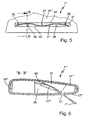
- Figure 5 shows, in an insertion direction, a portion of a visor body 10 '''having a receiving opening 3''' disposed therein.
- ribs 35-39 project into the cross section the receiving opening 3 "'.
- the ribs 35-39 have such a height at least in part of their extension along the insertion direction that each rib projects into the region between the two laterally adjacent ribs of the opposite wall region.
- the inserted between these ribs 35-39 object 2 ''' is bent along its front edge in the insertion direction and clamped in this way. In this case, the object 2 '''in the bent region assumes a wave-like shape.
- Figure 6 shows along the plane B-B in Figure 5, the sun visor with inter-protruding ribs 35 - 39 in a receiving area 31 '' '.
- the rib 36 which bends the article 2 '' 'in the direction of the opposite half-shell 11' '', and behind it the rib 37, which in turn bends the article in the direction of the opposite half-shell 12 '' '.
- the rib 36 is in one piece with the half-shell 12 '' ', the rib 37 formed integrally with the half-shell 11.
- the ribs 36 and 37 have a sloping contour towards the receiving opening 3 '' ', so that the object 2' '' can be pushed onto the ribs through the receiving opening 3 '' the rib 37 in the area between rib 37 and the next adjacent rib of the half-shell 11 '' '.
Landscapes
- Engineering & Computer Science (AREA)
- Mechanical Engineering (AREA)
- Vehicle Step Arrangements And Article Storage (AREA)
Claims (5)
- Pare-soleil (1) pour véhicules présentant un corps de pare-soleil (10) creux, constitué de deux demi-coques (11, 12) et un logement pour retenir un objet plat (2) tel qu'une carte à essence ou un ticket de stationnement, une ouverture de réception (3) en forme de fente étant réalisée dans le corps de pare-soleil (10), à travers laquelle l'objet (2) peut être enfoncé dans une région de réception (31) qui est disposée dans l'espace creux du corps de pare-soleil (10),
caractérisé en ce que
l'ouverture de réception (3) est disposée dans la face frontale du pare-soleil (1), l'objet (2) à retenir pouvant être introduit suivant un angle aigu par rapport à la surface frontale dans l'ouverture de réception (3), venant en appui contre la demi-coque opposée (11) lors de son insertion et étant maintenu serré entre les demi-coques (11, 12) s'il est inséré davantage. - Pare-soleil selon la revendication 1,
caractérisé en ce que
au moins l'une des demi-coques (11, 12) présente sur son côté intérieur des nervures (33, 33') au moyen desquelles l'objet reçu (2) est guidé. - Pare-soleil selon la revendication 1 ou 2,
caractérisé en ce qu'une
région d'appui flexible élastiquement (34) est réalisée dans la région de réception (31). - Pare-soleil selon la revendication 2,
caractérisé en ce que
l'objet (2) est courbé le long de son bord avant dans la direction d'insertion et est serré de cette manière, et à cet effet des nervures (35-39) orientées depuis deux parois opposées de la région de réception (31) le long de la direction d'insertion dépassent réciproquement en formant un recouvrement (42). - Pare-soleil selon l'une quelconque des revendications 1 à 4,
caractérisé en ce que
l'une des demi-coques (11, 12) présente, du côté intérieur, par portion, en particulier dans les régions d'appui de l'objet (2), des revêtements ou des doublures.
Applications Claiming Priority (3)
| Application Number | Priority Date | Filing Date | Title |
|---|---|---|---|
| DE10302675A DE10302675A1 (de) | 2003-01-24 | 2003-01-24 | Sonnenblende |
| DE10302675 | 2003-01-24 | ||
| PCT/EP2004/000382 WO2004065152A1 (fr) | 2003-01-24 | 2004-01-20 | Pare-soleil |
Publications (2)
| Publication Number | Publication Date |
|---|---|
| EP1585643A1 EP1585643A1 (fr) | 2005-10-19 |
| EP1585643B1 true EP1585643B1 (fr) | 2006-06-07 |
Family
ID=32667792
Family Applications (1)
| Application Number | Title | Priority Date | Filing Date |
|---|---|---|---|
| EP04703361A Expired - Lifetime EP1585643B1 (fr) | 2003-01-24 | 2004-01-20 | Pare-soleil |
Country Status (5)
| Country | Link |
|---|---|
| US (1) | US20070018476A1 (fr) |
| EP (1) | EP1585643B1 (fr) |
| JP (1) | JP2006513098A (fr) |
| DE (2) | DE10302675A1 (fr) |
| WO (1) | WO2004065152A1 (fr) |
Families Citing this family (4)
| Publication number | Priority date | Publication date | Assignee | Title |
|---|---|---|---|---|
| DE102006028048A1 (de) * | 2006-06-19 | 2007-12-27 | Audi Ag | Vorrichtung zur Führung eines in einem Gehäuse gelagerten Behälters |
| WO2009097382A1 (fr) * | 2008-01-31 | 2009-08-06 | Johnson Controls Technology Company | Pare-soleil moulé à l'arrière, moulé par injection |
| US8960762B2 (en) | 2012-07-17 | 2015-02-24 | Ford Global Technologies, Llc | Vehicle visor assembly with a center check clip |
| US8678468B2 (en) * | 2012-07-17 | 2014-03-25 | Ford Global Technologies, Llc | Vehicle visor assembly with a center check clip |
Family Cites Families (8)
| Publication number | Priority date | Publication date | Assignee | Title |
|---|---|---|---|---|
| US2278011A (en) * | 1939-07-24 | 1942-03-31 | Murdock Forrest Lee | Paper pack holder |
| US4353593A (en) * | 1979-12-31 | 1982-10-12 | Henson Artel R | Sun visor |
| DE4340685A1 (de) * | 1993-11-30 | 1995-06-01 | Happich Gmbh Gebr | Sonnenblende für Fahrzeuge |
| DE19635684B4 (de) * | 1996-09-03 | 2004-09-30 | Johnson Controls Interiors Gmbh & Co. Kg | Sonnenblende für Fahrzeuge |
| JP3636556B2 (ja) * | 1996-09-25 | 2005-04-06 | デルタ工業株式会社 | 自動車用のサンバイザ |
| JP2001055042A (ja) * | 1999-08-17 | 2001-02-27 | Neoex Lab Inc | ホルダを備えた車両用サンバイザ |
| US6585308B2 (en) * | 2000-11-09 | 2003-07-01 | Lear Corporation | Visor assembly with extender blade |
| US6604772B2 (en) * | 2001-11-09 | 2003-08-12 | Lear Corporation | Extender blade mounting frame for a sun visor |
-
2003
- 2003-01-24 DE DE10302675A patent/DE10302675A1/de not_active Withdrawn
-
2004
- 2004-01-20 DE DE502004000714T patent/DE502004000714D1/de not_active Expired - Lifetime
- 2004-01-20 US US10/543,170 patent/US20070018476A1/en not_active Abandoned
- 2004-01-20 JP JP2005518642A patent/JP2006513098A/ja not_active Abandoned
- 2004-01-20 WO PCT/EP2004/000382 patent/WO2004065152A1/fr not_active Ceased
- 2004-01-20 EP EP04703361A patent/EP1585643B1/fr not_active Expired - Lifetime
Also Published As
| Publication number | Publication date |
|---|---|
| DE10302675A1 (de) | 2004-08-05 |
| US20070018476A1 (en) | 2007-01-25 |
| EP1585643A1 (fr) | 2005-10-19 |
| WO2004065152A1 (fr) | 2004-08-05 |
| WO2004065152B1 (fr) | 2004-10-07 |
| JP2006513098A (ja) | 2006-04-20 |
| DE502004000714D1 (de) | 2006-07-20 |
Similar Documents
| Publication | Publication Date | Title |
|---|---|---|
| DE102018130152B4 (de) | Konsole mit einem Becherhalter | |
| DE202018103133U1 (de) | Innenraumkomponente eines Fahrzeugs | |
| EP2334512B1 (fr) | Element miroir | |
| US6962385B2 (en) | Sliding visor | |
| EP1716012B1 (fr) | Composant, notamment pare-soleil destine en particulier a un vehicule, et procede de fabrication d'un tel composant | |
| DE10116593B4 (de) | Fahrzeugdach | |
| DE10302675A1 (de) | Sonnenblende | |
| DE19518169A1 (de) | Abdeckeinrichtung zum Abdecken einer Öffnung in einer Wandung | |
| EP1008475A2 (fr) | Pare-soleil pour véhicules | |
| EP0402586A1 (fr) | Pare-soleil pour véhicules | |
| EP1612078B1 (fr) | Arrangement déflecteur de vent | |
| DE19731535A1 (de) | Sonnenblende für Fahrzeuge | |
| DE102010056291A1 (de) | Einsatzteil für einen Fahrzeuginnenraum und Fahrzeug mit einem Einsatzteil | |
| DE3032392C2 (de) | Außenspiegel für Fahrzeuge | |
| EP1184217B1 (fr) | Pare-soleil pour véhicules | |
| DE19742521A1 (de) | Blendschutzeinrichtung für ein Fahrzeug | |
| WO2012013340A1 (fr) | Pare-soleil et procédé pour son montage | |
| DE102006025647B4 (de) | Airbagabdeckung | |
| DE10315653A1 (de) | Staufach für den Innenraum eines Fahrzeugs, Verfahren und Material | |
| WO2013020802A1 (fr) | Fixation d'une pièce moulée par soufflage | |
| DE102009057085A1 (de) | Sonnenblende für Fahrzeuge | |
| DE29902601U1 (de) | Tasche für den Innenraum von Fahrzeugen | |
| DE102010004369B4 (de) | Lösbares Ablagebehältnis für die Aufbewahrung eines Gegenstandes, insbesondere einer Brille oder eines Mobiltelefons in einem Kraftfahrzeug | |
| EP1785314A1 (fr) | Compartiment de rangement pour véhicules automobiles | |
| WO2016016430A1 (fr) | Poche de cartes |
Legal Events
| Date | Code | Title | Description |
|---|---|---|---|
| PUAI | Public reference made under article 153(3) epc to a published international application that has entered the european phase |
Free format text: ORIGINAL CODE: 0009012 |
|
| 17P | Request for examination filed |
Effective date: 20050701 |
|
| AK | Designated contracting states |
Kind code of ref document: A1 Designated state(s): AT BE BG CH CY CZ DE DK EE ES FI FR GB GR HU IE IT LI LU MC NL PT RO SE SI SK TR |
|
| AX | Request for extension of the european patent |
Extension state: AL LT LV MK |
|
| GRAP | Despatch of communication of intention to grant a patent |
Free format text: ORIGINAL CODE: EPIDOSNIGR1 |
|
| RIN1 | Information on inventor provided before grant (corrected) |
Inventor name: PALLMER, DOMINIK |
|
| DAX | Request for extension of the european patent (deleted) | ||
| RBV | Designated contracting states (corrected) |
Designated state(s): DE ES FR GB IT SE |
|
| GRAS | Grant fee paid |
Free format text: ORIGINAL CODE: EPIDOSNIGR3 |
|
| GRAA | (expected) grant |
Free format text: ORIGINAL CODE: 0009210 |
|
| AK | Designated contracting states |
Kind code of ref document: B1 Designated state(s): DE ES FR GB IT SE |
|
| PG25 | Lapsed in a contracting state [announced via postgrant information from national office to epo] |
Ref country code: GB Free format text: LAPSE BECAUSE OF FAILURE TO SUBMIT A TRANSLATION OF THE DESCRIPTION OR TO PAY THE FEE WITHIN THE PRESCRIBED TIME-LIMIT Effective date: 20060607 Ref country code: IT Free format text: LAPSE BECAUSE OF FAILURE TO SUBMIT A TRANSLATION OF THE DESCRIPTION OR TO PAY THE FEE WITHIN THE PRESCRIBED TIME-LIMIT;WARNING: LAPSES OF ITALIAN PATENTS WITH EFFECTIVE DATE BEFORE 2007 MAY HAVE OCCURRED AT ANY TIME BEFORE 2007. THE CORRECT EFFECTIVE DATE MAY BE DIFFERENT FROM THE ONE RECORDED. Effective date: 20060607 |
|
| REG | Reference to a national code |
Ref country code: GB Ref legal event code: FG4D Free format text: NOT ENGLISH |
|
| REF | Corresponds to: |
Ref document number: 502004000714 Country of ref document: DE Date of ref document: 20060720 Kind code of ref document: P |
|
| PG25 | Lapsed in a contracting state [announced via postgrant information from national office to epo] |
Ref country code: SE Free format text: LAPSE BECAUSE OF FAILURE TO SUBMIT A TRANSLATION OF THE DESCRIPTION OR TO PAY THE FEE WITHIN THE PRESCRIBED TIME-LIMIT Effective date: 20060907 |
|
| PG25 | Lapsed in a contracting state [announced via postgrant information from national office to epo] |
Ref country code: ES Free format text: LAPSE BECAUSE OF FAILURE TO SUBMIT A TRANSLATION OF THE DESCRIPTION OR TO PAY THE FEE WITHIN THE PRESCRIBED TIME-LIMIT Effective date: 20060918 |
|
| GBV | Gb: ep patent (uk) treated as always having been void in accordance with gb section 77(7)/1977 [no translation filed] |
Effective date: 20060607 |
|
| PLBE | No opposition filed within time limit |
Free format text: ORIGINAL CODE: 0009261 |
|
| STAA | Information on the status of an ep patent application or granted ep patent |
Free format text: STATUS: NO OPPOSITION FILED WITHIN TIME LIMIT |
|
| RAP2 | Party data changed (patent owner data changed or rights of a patent transferred) |
Owner name: DAIMLERCHRYSLER AG |
|
| EN | Fr: translation not filed | ||
| 26N | No opposition filed |
Effective date: 20070308 |
|
| PG25 | Lapsed in a contracting state [announced via postgrant information from national office to epo] |
Ref country code: FR Free format text: LAPSE BECAUSE OF FAILURE TO SUBMIT A TRANSLATION OF THE DESCRIPTION OR TO PAY THE FEE WITHIN THE PRESCRIBED TIME-LIMIT Effective date: 20070309 |
|
| PG25 | Lapsed in a contracting state [announced via postgrant information from national office to epo] |
Ref country code: FR Free format text: LAPSE BECAUSE OF FAILURE TO SUBMIT A TRANSLATION OF THE DESCRIPTION OR TO PAY THE FEE WITHIN THE PRESCRIBED TIME-LIMIT Effective date: 20060607 |
|
| PGFP | Annual fee paid to national office [announced via postgrant information from national office to epo] |
Ref country code: DE Payment date: 20100121 Year of fee payment: 7 |
|
| REG | Reference to a national code |
Ref country code: DE Ref legal event code: R119 Ref document number: 502004000714 Country of ref document: DE Effective date: 20110802 |
|
| PG25 | Lapsed in a contracting state [announced via postgrant information from national office to epo] |
Ref country code: DE Free format text: LAPSE BECAUSE OF NON-PAYMENT OF DUE FEES Effective date: 20110802 |