EP1585618B1 - A tool compensating device for the computerized numerically controlled machine tool - Google Patents
A tool compensating device for the computerized numerically controlled machine tool Download PDFInfo
- Publication number
- EP1585618B1 EP1585618B1 EP03776038A EP03776038A EP1585618B1 EP 1585618 B1 EP1585618 B1 EP 1585618B1 EP 03776038 A EP03776038 A EP 03776038A EP 03776038 A EP03776038 A EP 03776038A EP 1585618 B1 EP1585618 B1 EP 1585618B1
- Authority
- EP
- European Patent Office
- Prior art keywords
- worm
- arm
- controlled machine
- computer numerical
- machine tool
- Prior art date
- Legal status (The legal status is an assumption and is not a legal conclusion. Google has not performed a legal analysis and makes no representation as to the accuracy of the status listed.)
- Expired - Lifetime
Links
- 230000000452 restraining effect Effects 0.000 claims description 2
- 230000006835 compression Effects 0.000 claims 2
- 238000007906 compression Methods 0.000 claims 2
- 238000012545 processing Methods 0.000 description 10
- 238000000034 method Methods 0.000 description 6
- 230000000694 effects Effects 0.000 description 2
- 238000013459 approach Methods 0.000 description 1
- 238000006073 displacement reaction Methods 0.000 description 1
- 238000005259 measurement Methods 0.000 description 1
Images


Classifications
-
- B—PERFORMING OPERATIONS; TRANSPORTING
- B23—MACHINE TOOLS; METAL-WORKING NOT OTHERWISE PROVIDED FOR
- B23Q—DETAILS, COMPONENTS, OR ACCESSORIES FOR MACHINE TOOLS, e.g. ARRANGEMENTS FOR COPYING OR CONTROLLING; MACHINE TOOLS IN GENERAL CHARACTERISED BY THE CONSTRUCTION OF PARTICULAR DETAILS OR COMPONENTS; COMBINATIONS OR ASSOCIATIONS OF METAL-WORKING MACHINES, NOT DIRECTED TO A PARTICULAR RESULT
- B23Q15/00—Automatic control or regulation of feed movement, cutting velocity or position of tool or work
-
- B—PERFORMING OPERATIONS; TRANSPORTING
- B23—MACHINE TOOLS; METAL-WORKING NOT OTHERWISE PROVIDED FOR
- B23Q—DETAILS, COMPONENTS, OR ACCESSORIES FOR MACHINE TOOLS, e.g. ARRANGEMENTS FOR COPYING OR CONTROLLING; MACHINE TOOLS IN GENERAL CHARACTERISED BY THE CONSTRUCTION OF PARTICULAR DETAILS OR COMPONENTS; COMBINATIONS OR ASSOCIATIONS OF METAL-WORKING MACHINES, NOT DIRECTED TO A PARTICULAR RESULT
- B23Q17/00—Arrangements for observing, indicating or measuring on machine tools
- B23Q17/22—Arrangements for observing, indicating or measuring on machine tools for indicating or measuring existing or desired position of tool or work
-
- G—PHYSICS
- G05—CONTROLLING; REGULATING
- G05B—CONTROL OR REGULATING SYSTEMS IN GENERAL; FUNCTIONAL ELEMENTS OF SUCH SYSTEMS; MONITORING OR TESTING ARRANGEMENTS FOR SUCH SYSTEMS OR ELEMENTS
- G05B2219/00—Program-control systems
- G05B2219/30—Nc systems
- G05B2219/37—Measurements
- G05B2219/37025—Retract, swing out of the way, measuring device during normal machining for protection
-
- G—PHYSICS
- G05—CONTROLLING; REGULATING
- G05B—CONTROL OR REGULATING SYSTEMS IN GENERAL; FUNCTIONAL ELEMENTS OF SUCH SYSTEMS; MONITORING OR TESTING ARRANGEMENTS FOR SUCH SYSTEMS OR ELEMENTS
- G05B2219/00—Program-control systems
- G05B2219/30—Nc systems
- G05B2219/37—Measurements
- G05B2219/37228—Tool inspection, condition, dull tool
-
- G—PHYSICS
- G05—CONTROLLING; REGULATING
- G05B—CONTROL OR REGULATING SYSTEMS IN GENERAL; FUNCTIONAL ELEMENTS OF SUCH SYSTEMS; MONITORING OR TESTING ARRANGEMENTS FOR SUCH SYSTEMS OR ELEMENTS
- G05B2219/00—Program-control systems
- G05B2219/30—Nc systems
- G05B2219/37—Measurements
- G05B2219/37241—Displacement of tool, miss inserted
-
- Y—GENERAL TAGGING OF NEW TECHNOLOGICAL DEVELOPMENTS; GENERAL TAGGING OF CROSS-SECTIONAL TECHNOLOGIES SPANNING OVER SEVERAL SECTIONS OF THE IPC; TECHNICAL SUBJECTS COVERED BY FORMER USPC CROSS-REFERENCE ART COLLECTIONS [XRACs] AND DIGESTS
- Y10—TECHNICAL SUBJECTS COVERED BY FORMER USPC
- Y10T—TECHNICAL SUBJECTS COVERED BY FORMER US CLASSIFICATION
- Y10T408/00—Cutting by use of rotating axially moving tool
- Y10T408/16—Cutting by use of rotating axially moving tool with control means energized in response to activator stimulated by condition sensor
- Y10T408/175—Cutting by use of rotating axially moving tool with control means energized in response to activator stimulated by condition sensor to control relative positioning of Tool and work
-
- Y—GENERAL TAGGING OF NEW TECHNOLOGICAL DEVELOPMENTS; GENERAL TAGGING OF CROSS-SECTIONAL TECHNOLOGIES SPANNING OVER SEVERAL SECTIONS OF THE IPC; TECHNICAL SUBJECTS COVERED BY FORMER USPC CROSS-REFERENCE ART COLLECTIONS [XRACs] AND DIGESTS
- Y10—TECHNICAL SUBJECTS COVERED BY FORMER USPC
- Y10T—TECHNICAL SUBJECTS COVERED BY FORMER US CLASSIFICATION
- Y10T82/00—Turning
- Y10T82/25—Lathe
- Y10T82/2502—Lathe with program control
-
- Y—GENERAL TAGGING OF NEW TECHNOLOGICAL DEVELOPMENTS; GENERAL TAGGING OF CROSS-SECTIONAL TECHNOLOGIES SPANNING OVER SEVERAL SECTIONS OF THE IPC; TECHNICAL SUBJECTS COVERED BY FORMER USPC CROSS-REFERENCE ART COLLECTIONS [XRACs] AND DIGESTS
- Y10—TECHNICAL SUBJECTS COVERED BY FORMER USPC
- Y10T—TECHNICAL SUBJECTS COVERED BY FORMER US CLASSIFICATION
- Y10T82/00—Turning
- Y10T82/25—Lathe
- Y10T82/2572—Attachment
-
- Y—GENERAL TAGGING OF NEW TECHNOLOGICAL DEVELOPMENTS; GENERAL TAGGING OF CROSS-SECTIONAL TECHNOLOGIES SPANNING OVER SEVERAL SECTIONS OF THE IPC; TECHNICAL SUBJECTS COVERED BY FORMER USPC CROSS-REFERENCE ART COLLECTIONS [XRACs] AND DIGESTS
- Y10—TECHNICAL SUBJECTS COVERED BY FORMER USPC
- Y10T—TECHNICAL SUBJECTS COVERED BY FORMER US CLASSIFICATION
- Y10T82/00—Turning
- Y10T82/25—Lathe
- Y10T82/2585—Tool rest
- Y10T82/2587—Turret type holder [e.g., multiple tools, etc.]
Definitions
- the present invention relates to a tool compensating apparatus for a computerized numerically controlled machine tool, according to the preamble of claim 1 (see, for example, JP-10309652 ).
- the computer numerical controlled machine tool automatically processes a work piece by using a computer after confirming the position of a cutting tool on a basis of a pre-programmed process condition such as a target processing measurement, a desired shape, a transferring speed of the cutting tool, etc.
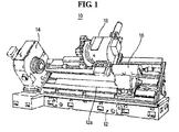
- FIG. 1 shows the conventional computer numerical controlled lathe 10.
- the computer numerical controlled lathe 10 comprises a frame 12 including a bed 12a, a headstock 14 for grasping and fixing one end of the work piece, which is fixed at one side of the frame 12, a tailstock 16 for grasping and fixing the other end of the work piece, which is sliderably positioned on the bed 12a in opposite to the headstock 14, a tool rest 18 for processing the work piece rotated between the headstock 14 and the tailstock 16 while moving along the longitudinal axis of the bed 12a on one side portion of the bed 12a of the frame 12, a control part (not shown) for controlling the headstock 14, the tailstock 16 and the tool rest 18.
- the work piece which is supported and rotated between the headstock 14 and the tailstock 16, is automatically processed by the cutting tool mounted to the tool rest 18 sliding on the bed 12a on a basis of the pre-programmed process condition.
- problems with the conventional computer numerical controlled machine tool as described above are that a cutting edge of the cutting tool for processing the work piece may be worn due to the friction between the cutting edge and the work piece and the processing precision of the cutting tool may deteriorate due to the change of the cutting tool's position.
- an apparatus for sensing a position of the cutting tool during operation of the processing the work piece for a limited time is installed at the computer numerical controlled lathe 10.
- FIG. 2 shows the apparatus for sensing a position of the cutting tool mounted to the computer numerical controlled machine tool, more particularly shows the state that it is mounted to the headstock of the computer numerical controlled machine tool.
- the apparatus 20 for sensing a position of the cutting tool comprises an arm 22 having a sensor 22a for sensing the position of the cutting tool, a gear assembly 24 for pivoting the arm 22 toward the cutting tool, and a driving motor (not shown) for driving the gear assembly 24.
- the arm 22 having the sensor 22a is moved toward the cutting tool by means of the gear assembly 24 and then the sensor 22a senses a position of the front end of the cutting tool. Thereafter, the sensor 22a provides the control part of the computer numerical controlled machine tool with a detected value.
- the control part of the computer numerical controlled machine tool compares the detected value input from the apparatus 20 for sensing a position of the cutting tool with a standard value, and then calculates a displacement of the cutting tool and it sends a control signal for compensating the position of the cutting tool to the computer numerical controlled machine tool in accordance with the result.
- the present invention has been developed to solve the above-mentioned problems. It is an object of the present invention to provide an apparatus for sensing a position of a cutting tool which is capable of preventing the overload from being applied the driving motor by stopping the driving motor from operating while a sensor sense the position of the cutting tool in a computer numerical controlled machine tool.
- the present invention provides a tool compensating apparatus as defined in claim 1.
- the gear assembly can include an idle gear that is engaged with a spur gear mounted to the driving motor, a worm wheel for pivoting the arm by engaging with the arm, a worm for rotating the worm wheel, and a worm shaft having the spur gear at its one end.
- the worm is sliderably mounted to the worm shaft.
- the worm shaft can include a staged portion that is formed at a position spaced a distance from the one end of the worm shaft toward the other end thereof.
- a flange is formed at the other end of the worm shaft.
- the worm is slidably mounted between the stage-shaped portion and the flange of the worm shaft.
- An elastic member for elastically supporting the worm is disposed between the worm and the flange of the worm shaft so as to restrain the slide movement of the worm.
- a cam pivoting with the worm wheel and a second sensor and a third sensor are disposed in the housing.
- the second and the third sensors are positioned in close proximity to the worm wheel and they are spaced with each other at a predetermined distance.
- the second and the third sensors sense the movement of the cam so as to detect the pivoting angles of the worm wheel.
- the tool compensating apparatus for the computer numerical controlled machine tool further comprises a stopper for restrain the rotation of the worm wheel in order to limit a pivoting angle of the arm in cooperation with the gear assembly.
- the second and the third sensors sense the movement of the cam and then supply a signal for stopping the operation of the driving motor to the control part of the computer numerical controlled machine tool when the cam passes through a standard position.
- the arm pivots in a range of predetermined angles.
- the second sensor judges whether the cam adjacent to the worm wheel passes by the second sensor or not.
- the second sensor supplies a signal for stopping the operation of the driving motor to the control part of the computer numerical controlled machine tool.
- the worm wheel tends to continuously rotate due to its inertial force. Accordingly, the worm engaged with the worm wheel moves toward the other end of the worm shaft along the worm shaft and it may alleviate the rotation of the worm wheel. Since the worm moves back to its initial position by means of the elastic member for elastically supporting the worm, the worm wheel may rotate in the reverse direction and thereby the cam moves a position to be sensed by the second sensor.
- the arm can stop a predetermined position in which the sensor precisely senses the position of the cutting tool.
- the arm can be precisely located at a sensing position in which a sensor can precisely sense the position of the cutting tool.
- the second and the third sensors sense the pivoting movement of the arm and control the operation of the driving motor, it is possible to hold the continuous operation of the driving motor and therefore to prevent the driving motor from being damaged due to the overload.
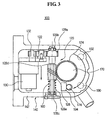
- FIG. 3 is a cross sectional view of the apparatus 100 for sensing the position of the cutting tool according to a preferred embodiment of the present invention, showing a state that a worm has been moved along a worm shaft at a predetermined distance due to the inertial force of a worm wheel while the driving motor 130 stops operating.
- FIG. 4 is a cross sectional view of the apparatus 100 for sensing the position of the cutting tool according to the preferred embodiment of the present invention, showing a state that the worm has been returned to its initial position due to operation of an elastic member.
- FIG. 5 is a longitudinal sectional view of the apparatus 100 for sensing the position of the cutting tool according to the preferred embodiment of the present invention, showing a state that the apparatus 100 for sensing the position of the cutting tool as shown in FIGS. 3 and 4 is rotated at 90 degrees against the axis of the worm shaft.
- the cutting tool 100 comprises a first sensor 22a for sensing the position of the cutting tool mounted to the tool rest in the computer numerical controlled machine tool; an arm 110 for moving the first sensor 22a to a position for sensing the position of the cutting tool; a gear assembly 120 for pivoting the arm 110 in a range of predetermined angles, the gear assembly 120 being combined to the arm 110; a driving motor 130 for supplying a driving force to the gear assembly 120 so as to rotate the arm 110; and a housing 140 for accommodating the gear assembly 120 and the driving motor 130.
- the housing 140 includes a main body 142 having an oval-shaped section, a cover 144 combined to the main body 142 at one side of the main body 142, and a supporting member 146 for supporting a shaft of one gear among the gears of the gear assembly 120, the supporting member 146 being combined to the main body 142 at the other side of the main body 142.
- the cover 144 and the supporting member 146 are combined to both sides of the main body 142 by means of a screw, respectively.
- the driving motor 130 comprises a servomotor.
- a spur gear 132 is mounted to a distal end of the rotational shaft of the driving motor 130.
- the arm 110 is fixed to a connecting member 150 by means of a screw where the connecting member is forcibly fitted into the other end of the shaft of the worm wheel, will be explained herein below. Accordingly, the arm 110 can rotate in the rotational direction of the shaft of the worm wheel.
- the arm 110 is provided with the first sensor 22a for sensing the position of the cutting tool at its distal end.
- the first sensor 22a mounted to the distal end of the arm 110 senses the position of the cutting tool when the arm 110 rotates and then reaches a set position in which the arm 110 faces to the cutting tool. Thereafter, the first sensor 22a provides the control part of the computer numerical controlled machine tool with a detected data.
- the arm 110 may pivot toward workspace in the computer numerical controlled machine tool due to the operation of the driving motor 130 and then reaches a sensing position at which the first sensor 22a senses the position of the cutting tool mounted to the tool rest 18. Alternatively, the arm may get away from workspace and then reaches an initial position at which the first sensor 22a stands ready for sensing the position of the cutting tool.
- the gear assembly 120 includes an idle gear 122 that is engaged with a spur gear 132 mounted to the driving motor 130; a worm wheel 124 for pivoting the arm 110 by engaging with the arm 110; a worm 126 for rotating the worm wheel 124; and a worm shaft 128 having a further spur gear 128a at its one end. At this time, the worm 126 is slidably mounted to the worm shaft 128.
- the idle gear 122 for reducing the rotational force of the driving motor 130 is disposed between the further spur gear 128a mounted to the worm shaft 128 of the gear assembly 120 and the spur gear 132 mounted to the distal end of the rotational shaft of the driving motor 130.
- Both ends of the worm shaft 128 are supported by bearings 128b,128c on the inner surface of the housing 140.
- the further spur gear 128a is mounted to the one end of the worm shaft 128 and is engaged with the idle gear 122 for receiving a rotational force from the driving motor 130 via the idle gear 122.
- a staged portion 128d is formed at a position spaced a distance from the one end of the worm shaft 128 toward the other end thereof along the axis of the worm shaft 128.
- a flange 128e is formed at the other end of the worm shaft 128.
- an elongated key groove (not shown) having predetermined width and depth is longitudinally formed at an outer periphery surface between the staged portion 128d and the flange 128e.
- the worm 126 is mounted onto the worm shaft 128 at the other end of the worm shaft 128 and it can reciprocally slide between the staged portion 128d and the flange 128e of the worm shaft 128.
- a key (not shown) for preventing the worm 126 from independently rotating with respect to the worm shaft 128 is inserted into the key groove formed at the worm shaft 128.
- the key slides along the worm shaft 128 together with the worm 126.
- An elastic member 160 for elastically restraining the slide movement of the worm 126 along the worm shaft 128 is disposed between the worm 126 mounted to the worm shaft 128 and the flange 128e of the worm shaft 128.
- the elastic member 160 comprises a coiled spring.
- the worm wheel 124 is mounted to one end of a worm wheel shaft 170 mounted to the supporting member 146 that is combined to the other side of the main body 142 of the housing 140.
- a recess 124a having a predetermined diameter is formed at a predetermined position on the one side surface of the worm wheel 124.
- An elastic member 124b having a predetermined elastic force is inserted into the recess 124a.
- a ball 124c is disposed at the open portion of the recess 124a so that it is elastically supported by the elastic member 124b.
- a staged portion 172 is formed at a middle portion of the worm wheel shaft 170. Furthermore, a screw is formed at one end of the worm wheel shaft 170.
- the other end of the worm wheel shaft 170 is rotatably engaged with the supporting member 146 of the housing 140 by means of a bearing 170a.
- the connecting member 150 for mounting the arm 110 is forcibly fitted into the other end of the worm wheel shaft 170 as shown in FIG. 5 .
- One end of the arm 110 is engaged with the connecting member 150 forcibly fitted into the other end of the worm wheel shaft 170 and it rotates together with the worm wheel shaft 170.
- a cam 174 pivoting with the worm wheel 124 and a second sensor 190 and a third sensor 192 are disposed in the housing 140.
- the second and the third sensors 190,192 are positioned in close proximity to the worm wheel 124 and they are spaced with each other at a predetermined distance.
- the second and the third sensors 190,192 sense the movement of the cam 174 so as to detect the pivoting angles of the worm wheel 124.
- the second and the third sensors 190,192 are disposed at the housing 140 so that they are spaced around the worm wheel 124 with each other at a predetermined radial distance corresponding to the pivoting angle of the arm 110 round the axis of the worm wheel shaft 170.
- the second sensor 190 senses the movement of the cam 174 and then supplies a sensing signal to the control part of the computer numerical controlled machine tool.
- the control part of the computer numerical controlled machine tool After receiving the sensing signal from the second sensor 190, the control part of the computer numerical controlled machine tool makes the driving motor 130 to stop so that it suppresses the rotation of the worm wheel 124 and the arm 110 mounted to the worm wheel shaft 170 and rotating together with the worm wheel 124.
- the third sensor 192 senses the movement of the cam 174 and then it sends a sensing signal to the control part of the computer numerical controlled machine tool.
- a stopper 194 is mounted to the other side of the housing 140 and it is spaced from the second sensor 190 at a predetermined distance.
- the stopper 194 makes the worm wheel 124 to stop in order to limit a pivoting angle of the arm 110 in cooperation with the worm 126 of the gear assembly 120 and the elastic spring 160.
- the arm 110 stops at its initial position while the tool rest moves in order to process a work piece.
- the cam 174 rotating together with the worm wheel 124 is coaxial with the axis of the third sensor 192.
- the arm 110 maintained its initial position is far away from the tool rest and the headstock such that it does not hinder cutting tool's operating during reciprocal movement of the cutting tool along the bed of the computer numerical controlled machine tool.
- one end of the work piece is fixed to the turret of the headstock and then the other end of the work piece is fixed to the tailstock after moving the tailstock so as to support the other end of the work piece. Consequently, the work piece is fixed in the computer numerical controlled machine tool.
- control part judges whether the cutting tool is correctly mounted to the tool rest at its initial position or not
- the driving motor 130 In order to detect the position of the cutting tool, the driving motor 130 operates and rotates. Thereby, the rotational force is transmitted to the worm 126 via the spur gear 132 mounted to the rotational axis of the driving motor 130 and the idle gear 122 engaged with the spur gear 132.
- the rotational force of the driving motor 130 is transmitted to the worm wheel 124 via the worm 126 and thereby the worm wheel shaft 170 for supporting the worm wheel 124, of which the arm 110 is mounted to the other end thereof by means of the connecting member 150, begins to be rotated.
- the arm 110 combined to the worm wheel shaft 170 is pivoted toward the cutting tool of the computer numerical controlled machine tool.
- the worm 126 and the worm wheel 124 rotate together due to the rotational force of the driving motor 130.
- the worm wheel 124 continuously rotates until the arm 110 reaches the stopper 194.
- the first sensor 22a installed at the front end of the arm 110 stops at the sensing position in order to sense the front end of the tool rest.
- the worm wheel 124 cannot be rotated. Under this state, if the driving motor 130 is operated for about a half second, the worm wheel shaft 170 may continuously rotate in the clockwise direction. At this time, the worm 126 engaged with the worm wheel 124 also rotates and then moves along the arrow direction (referred to FIG. 3 ). As a result, the other end of the worm 126 is spaced from the staged portion 128d of the worm shaft 128 at a predetermined distance and thereby the elastic spring 160 is compressed.
- the elastic force of the elastic spring 160 is applied to the worm 126 along the arrow direction (referred to FIG. 4 ). At this time, a rotational force is applied by the worm 126 to the worm wheel 124 in the clockwise direction.
- the driving motor 130 is not operating, the arm 110 is brought into contact with the stopper 194 and thereby the first sensor 22a is fixed at the sensing position.
- the driving motor 130 operates in the reverse rotational direction so as to return the arm 110 to its initial position.
- the driving motor 130 If the driving motor 130 is operated in the reverse rotational direction, the worm shaft 128 rotates in the counter-clockwise direction. Accordingly, the worm 126 also rotates in the counter-clockwise direction and continuously moves along the arrow direction by receiving the rotational force of the worm shaft 128 and the elastic force of the elastic spring 160 (referred to FIG. 4 ). Until the first sensor 22a of the arm 110 is positioned at the initial position, the worm wheel 170 engaged with the worm 126 rotates in the counter-clockwise direction.
- the second sensor 190 senses the movement of the cam 174 and transmits a sensing signal to the control part of the computer numerical controlled machine tool.
- the control part of the computer numerical controlled machine tool makes the driving motor 130 to stop as soon as receive the signal of sensing the movement of the cam 174 from the second sensor 190.
- the worm wheel shaft 170 combined to the arm 110 rotates together with the arm 110.
- the worm wheel 124 mounted to the worm wheel shaft 170 rotates together with the worm wheel shaft 170.
- the worm 126 engaged therewith receives the rotational force.
- the worm 126 is engaged with the spur gear 132 mounted to the rotational shaft of the driving motor 130 via the idle gear 122, it is possible to restrain the rotation of the worm 126. Accordingly, the worm 126 slides toward the other end of the worm shaft 128, that is, toward the flange 128e, along the worm shaft 128 at the arrow as shown in FIG. 3 in order to alleviate or release the rotational force transmitted from the worm wheel 124.
- the worm wheel 124 and the worm wheel shaft 170 stop rotating due to the alleviation of the rotational force of the worm wheel 124 and the worm wheel shaft 170.
- the cam 174 rotating together with the worm wheel 124 is contacted with the stopper 194.
- the stopper 194 makes the cam 174 to stop and also the worm wheel 124 stops rotating.
- the worm 126 moves back to its initial position due to operation of the elastic spring 160 disposed between the worm 126 of the wonn shaft 128 and the flange 128e. Accordingly, the worm wheel 124 engaging with the worm 126 is rotated in the reverse direction.
- the cam 174 is located on the axis of the second sensor 190 and the first sensor 22a installed to the arm 110 faces to the cutting tool mounted to the computer numerical controlled machine tool.
- the first sensor 22a mounted to the arm 110 faces to the cutting tool, it senses the mounting position of the cutting tool and sends a sensing signal to the control part of the computer numerical controlled machine tool.
- the control part compares the sensing signal of the first sensor 22a with a programmed positional data of the cutting tool and then compensates the position of the cutting tool if the position of the cutting tool is incorrect.
- the control part makes the arm 110 of the apparatus 100 for sensing the position of the cutting tool to return its initial position and transfers the tool rest to the working position.
- the arm 110 After compensating the position of the cutting tool, the arm 110 returns to its initial position.
- the rotational shaft of the driving motor 130 rotates in the reverse direction. Accordingly, the idle gear 122 engaged with the spur gear 132 mounted to the rotational shaft of the driving motor 130 also rotates in the reverse direction and thereby the rotational force is transmitted to the worm shaft 128.
- the worm 126 mounted to the worm shaft 128 is also rotated in the reverse direction and thereby the worm wheel 124 rotates in the reverse direction.
- the cam 174 rotating together with the worm wheel 124 the arm 110 combined to the other end of the worm wheel shaft 170 for supporting the worm wheel 124 rotate together with the worm wheel 124 in the reverse direction and then they return to their initial position.
- the third sensor 192 senses the movement of the cam 174 and thereby it sends a sensing signal to the control part of the computer numerical controlled machine tool.
- the control part After receiving the sensing signal from the third sensor 192, the control part makes the driving motor 130 to stop.
- the arm 110 continuously rotates in the reverse direction due to the inertia force and the worm wheel shaft 170 supporting the arm 110 and the worm wheel mounted to the worm wheel shaft 170 also continuously rotate in the reverse direction.
- the worm wheel shaft 170 supporting the worm wheel 124 and the arm 110 engaged with thereof stop reverse rotating.
- the arm 110 is positioned to its initial position, that is, on the axis of the third sensor 192.
- the cutting tool may be worn due to the friction against the work piece. Furthermore, the position of the cutting tool may be deviated from an initial set position due to the characteristic of the work piece and the processing time interval.
- the apparatus 100 senses the position of the cutting tool and then the positional error is compensated in accordance with the detected result.
- the arm can be precisely located at the sensing position in which a first sensor can precisely sense the position of the cutting tool.
- the second and the third sensors sense the pivoting movement of the arm and control the operation of the driving motor, it is possible to hold the continuous operating of the driving motor and therefore to prevent the driving motor from being damaged due to the overload.
Landscapes
- Engineering & Computer Science (AREA)
- Mechanical Engineering (AREA)
- Numerical Control (AREA)
- Automatic Control Of Machine Tools (AREA)
- Machine Tool Sensing Apparatuses (AREA)
- Automatic Tool Replacement In Machine Tools (AREA)
Applications Claiming Priority (3)
| Application Number | Priority Date | Filing Date | Title |
|---|---|---|---|
| KR2002075099 | 2002-11-29 | ||
| KR10-2002-0075099A KR100469009B1 (ko) | 2002-11-29 | 2002-11-29 | 컴퓨터 수치제어 선반기계용 공구보정장치 |
| PCT/KR2003/002612 WO2004050299A1 (en) | 2002-11-29 | 2003-11-29 | A tool compensating device for the computerized numerically controlled machine tool |
Publications (3)
| Publication Number | Publication Date |
|---|---|
| EP1585618A1 EP1585618A1 (en) | 2005-10-19 |
| EP1585618A4 EP1585618A4 (en) | 2007-11-14 |
| EP1585618B1 true EP1585618B1 (en) | 2009-02-04 |
Family
ID=36113895
Family Applications (1)
| Application Number | Title | Priority Date | Filing Date |
|---|---|---|---|
| EP03776038A Expired - Lifetime EP1585618B1 (en) | 2002-11-29 | 2003-11-29 | A tool compensating device for the computerized numerically controlled machine tool |
Country Status (10)
| Country | Link |
|---|---|
| US (1) | US8065941B2 (ko) |
| EP (1) | EP1585618B1 (ko) |
| JP (1) | JP4202322B2 (ko) |
| KR (1) | KR100469009B1 (ko) |
| CN (1) | CN1717297B (ko) |
| AT (1) | ATE422176T1 (ko) |
| AU (1) | AU2003284702A1 (ko) |
| DE (1) | DE60326084D1 (ko) |
| ES (1) | ES2316838T3 (ko) |
| WO (1) | WO2004050299A1 (ko) |
Families Citing this family (6)
| Publication number | Priority date | Publication date | Assignee | Title |
|---|---|---|---|---|
| US8069756B2 (en) * | 2002-11-29 | 2011-12-06 | Marposs Societa' Per Azioni | Apparatus for automatically detecting the position of the cutting tool in the computerized numerically controlled lathe |
| WO2005113180A1 (en) * | 2004-05-21 | 2005-12-01 | Marposs Societa' Per Azioni | Apparatus for automatically detecting the position of the cutting tool in the computerized numerically controlled lathe |
| KR100469009B1 (ko) | 2002-11-29 | 2005-02-02 | 마르포스티앤드이 주식회사 | 컴퓨터 수치제어 선반기계용 공구보정장치 |
| JP6434446B2 (ja) | 2016-04-28 | 2018-12-05 | ファナック株式会社 | 加工システム |
| US10675689B2 (en) * | 2017-10-31 | 2020-06-09 | Mackay Manufacturing, Inc. | Metal lathe and tooling calibration |
| EP4086039A1 (en) * | 2021-05-04 | 2022-11-09 | Renishaw PLC | A motorised measurement arm apparatus for a machine tool |
Citations (1)
| Publication number | Priority date | Publication date | Assignee | Title |
|---|---|---|---|---|
| JPH10309652A (ja) * | 1997-05-07 | 1998-11-24 | Murata Mach Ltd | ツール検出装置 |
Family Cites Families (37)
| Publication number | Priority date | Publication date | Assignee | Title |
|---|---|---|---|---|
| US3492894A (en) * | 1967-10-02 | 1970-02-03 | Heald Machine Co | Machine tool |
| DE1777070C3 (de) * | 1968-08-31 | 1974-12-12 | Index-Werke Kg Hahn & Tessky, 7300 Esslingen | Revolver-Drehautomat |
| US3740160A (en) * | 1970-05-26 | 1973-06-19 | Ikegai Iron Works Ltd | Numerical controlled boring machine |
| DE2040020A1 (de) * | 1970-08-12 | 1972-02-17 | Ludwigsburger Maschb Gmbh | Bohreinheit,insbesondere zur Durchfuehrung von Feinbohrarbeiten |
| US4055386A (en) * | 1973-05-16 | 1977-10-25 | The Cross Company | Control system for compensating for machine tool wear |
| KR790000775B1 (en) | 1975-04-28 | 1979-06-30 | Asahi Chemical Ind | Manufacturing method of poly ethylene |
| FR2400014A1 (fr) * | 1977-08-09 | 1979-03-09 | Rhone Poulenc Ind | Preparation d'oligoimides |
| US4204782A (en) * | 1978-06-09 | 1980-05-27 | Beck Hans W | Automatic sizing system for numerically controlled machine |
| US4335498A (en) * | 1979-03-08 | 1982-06-22 | Textron, Inc. | Machine tool |
| US4425061A (en) * | 1981-09-14 | 1984-01-10 | Colt Industries Operating Corp | Tool setting device for machining center |
| EP0093288A1 (de) * | 1982-05-03 | 1983-11-09 | Werkzeugmaschinenfabrik Oerlikon-Bührle AG | Vorrichtung zur automatischen Verstellung der Radialposition eines Planschiebers eines Planverstellkopfes an einer Zerspanungsmaschine |
| US4902175A (en) * | 1984-09-12 | 1990-02-20 | Hermann Pfauter Gmbh & Co. | Method and apparatus for determining the angular position of a workpiece and positioning the same |
| JPH0632894B2 (ja) * | 1985-03-20 | 1994-05-02 | 豊田工機株式会社 | カム研削装置 |
| US4784541A (en) * | 1986-04-21 | 1988-11-15 | Kabushiki Kaisha Sankyo Seiki Seisakusho | High-precision equipment |
| FR2600002B1 (fr) | 1986-06-12 | 1988-10-21 | Krasnod Stankostroitelny Za | Dispositif de controle de la portee d'une arete tranchante d'un outil d'une machine-outil pour l'usinage de metaux par enlevement de copeaux |
| US5066176A (en) * | 1987-06-18 | 1991-11-19 | Kearney & Trecker Corporation | Probe for machine tool |
| US4806155A (en) | 1987-07-15 | 1989-02-21 | Crucible Materials Corporation | Method for producing dysprosium-iron-boron alloy powder |
| JPH01150826A (ja) | 1987-12-07 | 1989-06-13 | Fuji Photo Film Co Ltd | 過負荷検出機構 |
| JPH04202322A (ja) | 1990-11-29 | 1992-07-23 | Kanebo Ltd | ポリエステルの製造方法 |
| US5127778A (en) * | 1991-05-14 | 1992-07-07 | Scheer Wayne T | Musical reed duplication |
| JPH0639686Y2 (ja) * | 1991-11-08 | 1994-10-19 | 株式会社モリタ製作所 | 根管長測定機能付き超音波治療器 |
| JPH05162002A (ja) | 1991-12-13 | 1993-06-29 | Kiwa Giken Kk | 加工物の寸法及び位置検出装置を備えた複合加工機械 |
| TW240188B (ko) * | 1993-06-04 | 1995-02-11 | Omi Tadahiro | |
| JPH07100736A (ja) * | 1993-09-30 | 1995-04-18 | Fanuc Ltd | 主軸位置測定装置 |
| JPH07124849A (ja) | 1993-10-29 | 1995-05-16 | Komatsu Ltd | 工作機械における工具取付位置の補正装置およびその補正方法 |
| EP0761383A3 (de) * | 1995-09-02 | 1997-10-22 | Chiron Werke Gmbh | Werkzeugmaschine |
| KR19980053785U (ko) | 1996-12-31 | 1998-10-07 | 추호석 | 공작기계의 공구 보정장치 |
| DE69707852D1 (de) * | 1997-07-18 | 2001-12-06 | Vn Sa Moutier | Stangenzuführvorrichtung für eine Werkzeugmaschine, insbesondere einen Drehautomaten |
| JPH11138377A (ja) * | 1997-11-13 | 1999-05-25 | Toshiba Mach Co Ltd | 自動工具交換装置 |
| JPH11188572A (ja) | 1997-12-24 | 1999-07-13 | Minoru Okada | Nc工作機械の工具交換時における刃先位置設定方法及び、この方法を実行するnc工作機械 |
| US6060855A (en) * | 1998-02-05 | 2000-05-09 | Metrol Co., Ltd. | Moving apparatus for arm of tool edge sensor |
| JP4351379B2 (ja) * | 2000-11-02 | 2009-10-28 | 村田機械株式会社 | 工作機械 |
| US6481939B1 (en) * | 2001-08-24 | 2002-11-19 | Robb S. Gillespie | Tool tip conductivity contact sensor and method |
| KR100482583B1 (ko) | 2002-11-15 | 2005-04-14 | 현대자동차주식회사 | 체인 호이스트용 밸런스 조절장치 |
| US8069756B2 (en) * | 2002-11-29 | 2011-12-06 | Marposs Societa' Per Azioni | Apparatus for automatically detecting the position of the cutting tool in the computerized numerically controlled lathe |
| KR100469009B1 (ko) | 2002-11-29 | 2005-02-02 | 마르포스티앤드이 주식회사 | 컴퓨터 수치제어 선반기계용 공구보정장치 |
| KR20050023157A (ko) | 2003-08-27 | 2005-03-09 | 현대자동차주식회사 | 보링 머신용 접촉 센싱 장치 |
-
2002
- 2002-11-29 KR KR10-2002-0075099A patent/KR100469009B1/ko active IP Right Grant
-
2003
- 2003-11-29 CN CN2003801044420A patent/CN1717297B/zh not_active Expired - Fee Related
- 2003-11-29 EP EP03776038A patent/EP1585618B1/en not_active Expired - Lifetime
- 2003-11-29 ES ES03776038T patent/ES2316838T3/es not_active Expired - Lifetime
- 2003-11-29 AU AU2003284702A patent/AU2003284702A1/en not_active Abandoned
- 2003-11-29 DE DE60326084T patent/DE60326084D1/de not_active Expired - Lifetime
- 2003-11-29 US US10/536,391 patent/US8065941B2/en not_active Expired - Fee Related
- 2003-11-29 JP JP2004556959A patent/JP4202322B2/ja not_active Expired - Fee Related
- 2003-11-29 WO PCT/KR2003/002612 patent/WO2004050299A1/en active Application Filing
- 2003-11-29 AT AT03776038T patent/ATE422176T1/de active
Patent Citations (1)
| Publication number | Priority date | Publication date | Assignee | Title |
|---|---|---|---|---|
| JPH10309652A (ja) * | 1997-05-07 | 1998-11-24 | Murata Mach Ltd | ツール検出装置 |
Also Published As
| Publication number | Publication date |
|---|---|
| KR20040047042A (ko) | 2004-06-05 |
| CN1717297A (zh) | 2006-01-04 |
| EP1585618A4 (en) | 2007-11-14 |
| WO2004050299A1 (en) | 2004-06-17 |
| EP1585618A1 (en) | 2005-10-19 |
| US8065941B2 (en) | 2011-11-29 |
| AU2003284702A1 (en) | 2004-06-23 |
| ATE422176T1 (de) | 2009-02-15 |
| ES2316838T3 (es) | 2009-04-16 |
| DE60326084D1 (de) | 2009-03-19 |
| CN1717297B (zh) | 2010-04-28 |
| US20060037443A1 (en) | 2006-02-23 |
| JP2006507952A (ja) | 2006-03-09 |
| JP4202322B2 (ja) | 2008-12-24 |
| KR100469009B1 (ko) | 2005-02-02 |
Similar Documents
| Publication | Publication Date | Title |
|---|---|---|
| TWI686263B (zh) | 工作機械 | |
| JP5156742B2 (ja) | シート又はスキンへの切削弱化部の加工のための装置 | |
| KR920700797A (ko) | 시트 금속 작업기계용 금속시트를 위치시키는 방법 | |
| EP1585618B1 (en) | A tool compensating device for the computerized numerically controlled machine tool | |
| US5108117A (en) | Workpart chuck positioning mechanism with independent shoes | |
| US5213348A (en) | Workpart chuck positioning mechanism with independent shoes | |
| US10695878B2 (en) | Tool change rotary position determining device and tool change rotary position determining method | |
| JPH0530586B2 (ko) | ||
| US8069756B2 (en) | Apparatus for automatically detecting the position of the cutting tool in the computerized numerically controlled lathe | |
| KR20170094248A (ko) | 중심 공작물 영역을 지지 및 측정하기 위한 측정 스테디 레스트, 이 측정 스테디 레스트를 갖는 연삭기, 및 중심 공작물 영역을 지지 및 측정하기 위한 방법 | |
| JP7088808B2 (ja) | 工具交換装置及び工作機械 | |
| EP1753568A1 (en) | Apparatus for automatically detecting the position of the cutting tool in the computerized numerically controlled lathe | |
| US6082016A (en) | Cutting edge measuring device for machine tool | |
| KR20160079069A (ko) | 공구 그립퍼 장치 | |
| US4887500A (en) | Ball turner for turning lathes | |
| US4934882A (en) | Apparatus for monitoring the angular position of a workpiece | |
| WO2017051445A1 (ja) | 多関節ロボットのティーチングシステム | |
| EP0890412A1 (en) | Indexing apparatus and method for controlling the indexing apparatus | |
| JP3577887B2 (ja) | ツール検出装置 | |
| CN110181523A (zh) | 机器人 | |
| JPH0561075B2 (ko) | ||
| JP6897395B2 (ja) | 加工装置 | |
| WO2022003739A1 (en) | Workpiece rotation control system on a paneling machine and paneling machine including such system | |
| JPH0332554A (ja) | インプロセス工具自動補正装置 | |
| KR0117929Y1 (ko) | Cnc 선반용 공구 자동계측 장치의 측정위치 미세 조정기구 |
Legal Events
| Date | Code | Title | Description |
|---|---|---|---|
| PUAI | Public reference made under article 153(3) epc to a published international application that has entered the european phase |
Free format text: ORIGINAL CODE: 0009012 |
|
| 17P | Request for examination filed |
Effective date: 20050629 |
|
| AK | Designated contracting states |
Kind code of ref document: A1 Designated state(s): AT BE BG CH CY CZ DE DK EE ES FI FR GB GR HU IE IT LI LU MC NL PT RO SE SI SK TR |
|
| AX | Request for extension of the european patent |
Extension state: AL LT LV MK |
|
| DAX | Request for extension of the european patent (deleted) | ||
| RIN1 | Information on inventor provided before grant (corrected) |
Inventor name: D'ANTONIO, MARIO |
|
| A4 | Supplementary search report drawn up and despatched |
Effective date: 20071017 |
|
| RIC1 | Information provided on ipc code assigned before grant |
Ipc: B23Q 15/00 20060101AFI20040622BHEP Ipc: B23Q 16/00 20060101ALI20071011BHEP |
|
| RAP1 | Party data changed (applicant data changed or rights of an application transferred) |
Owner name: MARPOSS SOCIETA' PER AZIONI |
|
| 17Q | First examination report despatched |
Effective date: 20080428 |
|
| GRAP | Despatch of communication of intention to grant a patent |
Free format text: ORIGINAL CODE: EPIDOSNIGR1 |
|
| GRAS | Grant fee paid |
Free format text: ORIGINAL CODE: EPIDOSNIGR3 |
|
| GRAA | (expected) grant |
Free format text: ORIGINAL CODE: 0009210 |
|
| AK | Designated contracting states |
Kind code of ref document: B1 Designated state(s): AT BE BG CH CY CZ DE DK EE ES FI FR GB GR HU IE IT LI LU MC NL PT RO SE SI SK TR |
|
| REG | Reference to a national code |
Ref country code: GB Ref legal event code: FG4D |
|
| REG | Reference to a national code |
Ref country code: CH Ref legal event code: EP |
|
| REG | Reference to a national code |
Ref country code: IE Ref legal event code: FG4D |
|
| REF | Corresponds to: |
Ref document number: 60326084 Country of ref document: DE Date of ref document: 20090319 Kind code of ref document: P |
|
| REG | Reference to a national code |
Ref country code: ES Ref legal event code: FG2A Ref document number: 2316838 Country of ref document: ES Kind code of ref document: T3 |
|
| REG | Reference to a national code |
Ref country code: SE Ref legal event code: TRGR |
|
| NLV1 | Nl: lapsed or annulled due to failure to fulfill the requirements of art. 29p and 29m of the patents act | ||
| PG25 | Lapsed in a contracting state [announced via postgrant information from national office to epo] |
Ref country code: FI Free format text: LAPSE BECAUSE OF FAILURE TO SUBMIT A TRANSLATION OF THE DESCRIPTION OR TO PAY THE FEE WITHIN THE PRESCRIBED TIME-LIMIT Effective date: 20090204 Ref country code: NL Free format text: LAPSE BECAUSE OF FAILURE TO SUBMIT A TRANSLATION OF THE DESCRIPTION OR TO PAY THE FEE WITHIN THE PRESCRIBED TIME-LIMIT Effective date: 20090204 Ref country code: SI Free format text: LAPSE BECAUSE OF FAILURE TO SUBMIT A TRANSLATION OF THE DESCRIPTION OR TO PAY THE FEE WITHIN THE PRESCRIBED TIME-LIMIT Effective date: 20090204 |
|
| PG25 | Lapsed in a contracting state [announced via postgrant information from national office to epo] |
Ref country code: BE Free format text: LAPSE BECAUSE OF FAILURE TO SUBMIT A TRANSLATION OF THE DESCRIPTION OR TO PAY THE FEE WITHIN THE PRESCRIBED TIME-LIMIT Effective date: 20090204 |
|
| PG25 | Lapsed in a contracting state [announced via postgrant information from national office to epo] |
Ref country code: PT Free format text: LAPSE BECAUSE OF FAILURE TO SUBMIT A TRANSLATION OF THE DESCRIPTION OR TO PAY THE FEE WITHIN THE PRESCRIBED TIME-LIMIT Effective date: 20090706 Ref country code: EE Free format text: LAPSE BECAUSE OF FAILURE TO SUBMIT A TRANSLATION OF THE DESCRIPTION OR TO PAY THE FEE WITHIN THE PRESCRIBED TIME-LIMIT Effective date: 20090204 Ref country code: DK Free format text: LAPSE BECAUSE OF FAILURE TO SUBMIT A TRANSLATION OF THE DESCRIPTION OR TO PAY THE FEE WITHIN THE PRESCRIBED TIME-LIMIT Effective date: 20090204 |
|
| PG25 | Lapsed in a contracting state [announced via postgrant information from national office to epo] |
Ref country code: RO Free format text: LAPSE BECAUSE OF FAILURE TO SUBMIT A TRANSLATION OF THE DESCRIPTION OR TO PAY THE FEE WITHIN THE PRESCRIBED TIME-LIMIT Effective date: 20090204 Ref country code: SK Free format text: LAPSE BECAUSE OF FAILURE TO SUBMIT A TRANSLATION OF THE DESCRIPTION OR TO PAY THE FEE WITHIN THE PRESCRIBED TIME-LIMIT Effective date: 20090204 |
|
| PLBE | No opposition filed within time limit |
Free format text: ORIGINAL CODE: 0009261 |
|
| STAA | Information on the status of an ep patent application or granted ep patent |
Free format text: STATUS: NO OPPOSITION FILED WITHIN TIME LIMIT |
|
| 26N | No opposition filed |
Effective date: 20091105 |
|
| PG25 | Lapsed in a contracting state [announced via postgrant information from national office to epo] |
Ref country code: BG Free format text: LAPSE BECAUSE OF FAILURE TO SUBMIT A TRANSLATION OF THE DESCRIPTION OR TO PAY THE FEE WITHIN THE PRESCRIBED TIME-LIMIT Effective date: 20090504 |
|
| PG25 | Lapsed in a contracting state [announced via postgrant information from national office to epo] |
Ref country code: MC Free format text: LAPSE BECAUSE OF NON-PAYMENT OF DUE FEES Effective date: 20091130 |
|
| PG25 | Lapsed in a contracting state [announced via postgrant information from national office to epo] |
Ref country code: IE Free format text: LAPSE BECAUSE OF NON-PAYMENT OF DUE FEES Effective date: 20091129 Ref country code: GR Free format text: LAPSE BECAUSE OF FAILURE TO SUBMIT A TRANSLATION OF THE DESCRIPTION OR TO PAY THE FEE WITHIN THE PRESCRIBED TIME-LIMIT Effective date: 20090505 |
|
| PGFP | Annual fee paid to national office [announced via postgrant information from national office to epo] |
Ref country code: TR Payment date: 20101129 Year of fee payment: 8 |
|
| PG25 | Lapsed in a contracting state [announced via postgrant information from national office to epo] |
Ref country code: LU Free format text: LAPSE BECAUSE OF NON-PAYMENT OF DUE FEES Effective date: 20091129 |
|
| PG25 | Lapsed in a contracting state [announced via postgrant information from national office to epo] |
Ref country code: HU Free format text: LAPSE BECAUSE OF FAILURE TO SUBMIT A TRANSLATION OF THE DESCRIPTION OR TO PAY THE FEE WITHIN THE PRESCRIBED TIME-LIMIT Effective date: 20090805 |
|
| PG25 | Lapsed in a contracting state [announced via postgrant information from national office to epo] |
Ref country code: CY Free format text: LAPSE BECAUSE OF FAILURE TO SUBMIT A TRANSLATION OF THE DESCRIPTION OR TO PAY THE FEE WITHIN THE PRESCRIBED TIME-LIMIT Effective date: 20090204 |
|
| PGFP | Annual fee paid to national office [announced via postgrant information from national office to epo] |
Ref country code: SE Payment date: 20111121 Year of fee payment: 9 |
|
| PG25 | Lapsed in a contracting state [announced via postgrant information from national office to epo] |
Ref country code: SE Free format text: LAPSE BECAUSE OF NON-PAYMENT OF DUE FEES Effective date: 20121130 |
|
| PG25 | Lapsed in a contracting state [announced via postgrant information from national office to epo] |
Ref country code: TR Free format text: LAPSE BECAUSE OF NON-PAYMENT OF DUE FEES Effective date: 20121129 |
|
| REG | Reference to a national code |
Ref country code: FR Ref legal event code: PLFP Year of fee payment: 13 |
|
| REG | Reference to a national code |
Ref country code: FR Ref legal event code: PLFP Year of fee payment: 14 |
|
| REG | Reference to a national code |
Ref country code: FR Ref legal event code: PLFP Year of fee payment: 15 |
|
| PGFP | Annual fee paid to national office [announced via postgrant information from national office to epo] |
Ref country code: FR Payment date: 20171124 Year of fee payment: 15 Ref country code: CZ Payment date: 20171024 Year of fee payment: 15 |
|
| PGFP | Annual fee paid to national office [announced via postgrant information from national office to epo] |
Ref country code: CH Payment date: 20171123 Year of fee payment: 15 Ref country code: AT Payment date: 20171122 Year of fee payment: 15 |
|
| PGFP | Annual fee paid to national office [announced via postgrant information from national office to epo] |
Ref country code: DE Payment date: 20181203 Year of fee payment: 16 |
|
| PGFP | Annual fee paid to national office [announced via postgrant information from national office to epo] |
Ref country code: GB Payment date: 20181123 Year of fee payment: 16 Ref country code: IT Payment date: 20181130 Year of fee payment: 16 Ref country code: ES Payment date: 20181214 Year of fee payment: 16 |
|
| REG | Reference to a national code |
Ref country code: CH Ref legal event code: PL |
|
| REG | Reference to a national code |
Ref country code: AT Ref legal event code: MM01 Ref document number: 422176 Country of ref document: AT Kind code of ref document: T Effective date: 20181129 |
|
| PG25 | Lapsed in a contracting state [announced via postgrant information from national office to epo] |
Ref country code: CZ Free format text: LAPSE BECAUSE OF NON-PAYMENT OF DUE FEES Effective date: 20181129 |
|
| PG25 | Lapsed in a contracting state [announced via postgrant information from national office to epo] |
Ref country code: CH Free format text: LAPSE BECAUSE OF NON-PAYMENT OF DUE FEES Effective date: 20181130 Ref country code: LI Free format text: LAPSE BECAUSE OF NON-PAYMENT OF DUE FEES Effective date: 20181130 |
|
| PG25 | Lapsed in a contracting state [announced via postgrant information from national office to epo] |
Ref country code: FR Free format text: LAPSE BECAUSE OF NON-PAYMENT OF DUE FEES Effective date: 20181130 Ref country code: AT Free format text: LAPSE BECAUSE OF NON-PAYMENT OF DUE FEES Effective date: 20181129 |
|
| REG | Reference to a national code |
Ref country code: DE Ref legal event code: R119 Ref document number: 60326084 Country of ref document: DE |
|
| GBPC | Gb: european patent ceased through non-payment of renewal fee |
Effective date: 20191129 |
|
| PG25 | Lapsed in a contracting state [announced via postgrant information from national office to epo] |
Ref country code: GB Free format text: LAPSE BECAUSE OF NON-PAYMENT OF DUE FEES Effective date: 20191129 Ref country code: DE Free format text: LAPSE BECAUSE OF NON-PAYMENT OF DUE FEES Effective date: 20200603 Ref country code: IT Free format text: LAPSE BECAUSE OF NON-PAYMENT OF DUE FEES Effective date: 20191129 |
|
| REG | Reference to a national code |
Ref country code: ES Ref legal event code: FD2A Effective date: 20210528 |
|
| PG25 | Lapsed in a contracting state [announced via postgrant information from national office to epo] |
Ref country code: ES Free format text: LAPSE BECAUSE OF NON-PAYMENT OF DUE FEES Effective date: 20191130 |